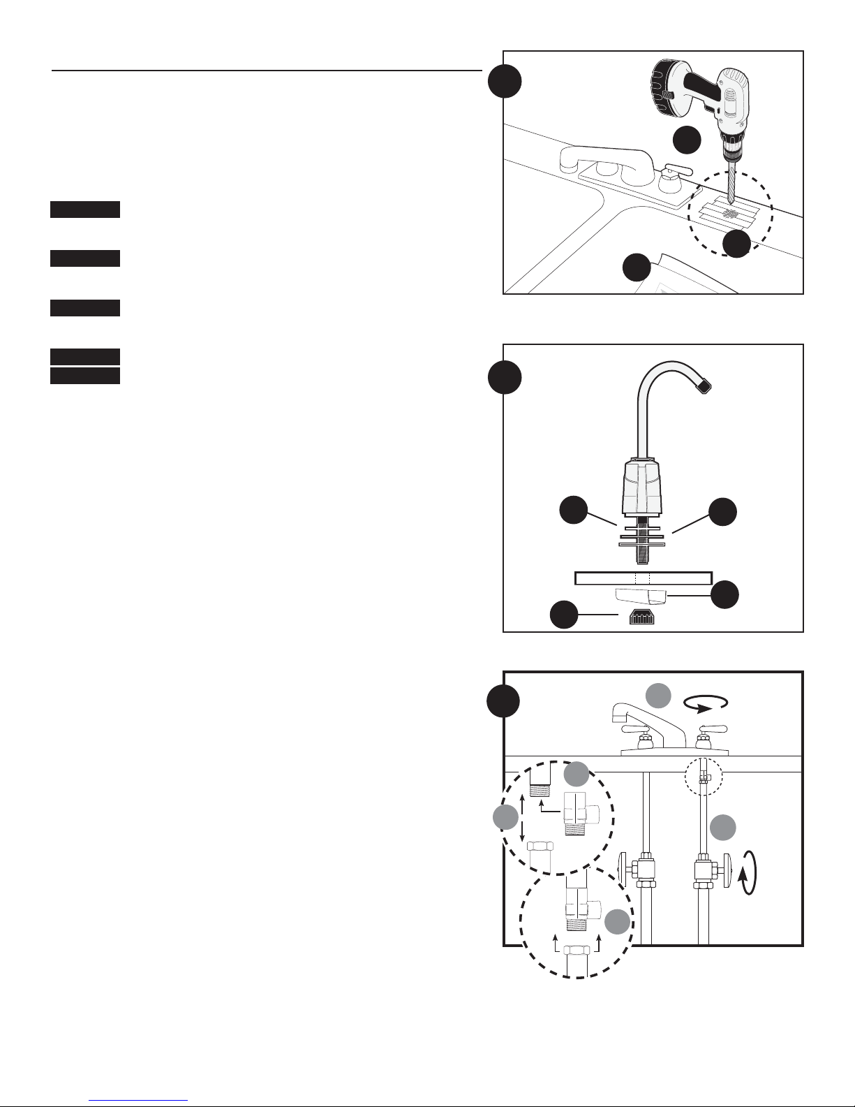
Cylligan SY-750S User manual

Specifications
Pressure Range: 30–125 psi (2.1–8.62 bar)
Temperature Range: 40–100°F (4.4–37.7°C)
Rated Service Flow: 0.75 gpm (2.8 Lpm)
Filter Capacity: 2500 gallons (9460 L)
Turbidity: 5 NTU max
Parts Included:
• Filter head with built-in bracket and compression fittings
• 750R filter cartridge
• Screws for mounting bracket
• Water supply adapter
• Lead-free drinking water faucet
• 1/4" plastic tubing
Technical Support: 1-800-645-5426
(M-F 7:30 am - 5:00 pm CST) 146153RevA 03/04
Easy-Change Under-Sink Drinking Water Filter
System Installation and Operating Instructions
Model SY-750S
TheSY-750S with750R or1000R replacementcartridge isTestedand Certified by
NSFInternational toNSF/ANSI Standard42 forthe aestheticreduction ofTaste
andOdor andChlorine andParticulateClass I*, Standard 53 for the reduction of
Cysts*,Lead*, Lindane*,Atrazine*,and Turbidity*.
•Phillips Screwdriver
•Utility Knife (for plastic tubing)
•Towel
•Pencil
•Tape Measure
•Adjustable Wrench
•Safety Glasses
Tools Required
•Center Punch
•1/4" and 1/2" Drill Bit •Hand or electric drill (cordless recommended)
Optional Materials
• Make certain that installation complies with
all state and local laws and regulations.
• The contaminants or other substances removed or
reduced by the selected
cartridge are not necessarily in your water. Ask your local water municipality
for a copy of their water analysis, or have your private well tested by a
reputable water testing lab.
• After prolongedperiods ofnon-use(such asduring avacation) itisrecommended
that the system be flushed thoroughly. Let water run for 2-3 minutes before
using.
• The filter cartridge used with this system has a limited service life. Changes in
taste, odor, color; and/or flow of the water being filtered indicate that the
cartridge should be replaced.
Precautions
WARNING: Do not use with water that is microbiologically unsafe or of
unknown quality without adequate disinfection before or after the system.
CAUTION: This filter must be protected from freezing, which can cause cracking
of the filter and water leakage.
CAUTION: Because of the product’s limited service life and to prevent costly
repairs or possible water damage, we strongly recommend that the head of the
filter be replaced every ten years. If the head of your filter has been in use for
longer than this period, it should be replaced immediately. Date the top of any
new head to indicate the next recommended replacement date.
CAUTION: Turn off water supply to head without cartridge if it must be left
unattended for an extended period of time.
NOTE:
• For cold water use only. *Appliesto 1000Rreplacement cartridgeonly.

Installation
• For standard installation on 1⁄2-inch 14 NPS threads (most common thread on kitchen faucets)
cold water line.
• Please read all instructions and precautions before installing and using your SY-750S
under-sink water filter.
• Numbered diagrams correspond with numbered steps.
1. Selecting the Faucet Location
NOTE: The drinking water faucet should be positioned with function, convenience, and
appearance in mind. An adequate flat area is required to allow faucet base to rest securely. The
faucet fits through a 7⁄16-inch hole. Most sinks have pre-drilled 13⁄8-inch or 11⁄2-inch diameter holes
that may be used for faucet installation or spray hose. If these pre-drilled holes cannot be used or
are in an inconvenient location, it will be necessary to drill a 1⁄2-inch hole in the sink for the faucet.
CAUTION: Thisprocedure may generatedusts which cancause severe irritationif inhaled orcome
incontact with theeyes. The useof safety glassesand respirator forthis procedure isrecommended.
CAUTION: DO NOT ATTEMPT TO DRILL THROUGH AN ALL-PORCELAIN OR PORCELAIN-COATED
SINK. For applications on these types of sinks we recommend using the sprayer hole or
mounting the faucet through the countertop.
CAUTION: When drilling through a countertop make sure the area below the drilled area is free of
wiring and piping. Make certain that you have ample room to make the proper connections to the
bottom of the faucet.
CAUTION: Do not drill through a countertop that is more than 1-inch thick.
CAUTION: Do not attempt to drill through a tiled, marble, granite or similar countertop. Consult a
plumber or the countertop manufacturer for advice or assistance.
(A) Line bottom of sink with newspaper to prevent metal shavings, parts, or tools from falling
down drain.
(B) Place masking tape over the area to be drilled to prevent scratches if drill bit slips.
(C) Mark hole with center punch. Use a 1⁄4-inch drill bit for a pilot hole, then, using a 1⁄2-inch drill
bit, drill a hole completely through the sink. Smooth rough edges with a file.
2. Mounting the Faucet
(A) Slide small black rubber gasket OR
(B) gasket, aluminum escutcheon plate (remove protective plastic on aluminum escutcheon plate)
and large gasket onto threaded faucet stem. Lower faucet stem through hole in the sink.
NOTE: Black rubber gasket is designed for smaller holes in sink. Aluminum escutcheon plate with
gaskets is designed for larger, pre-drilled holes.
(C) Slide aluminum channel washer up faucet stem, followed by
(D)black plastic stem nut. Tighten nut with fingers.
NOTE: Do not use pliers to tighten stem-nut. Pliers may strip threads of faucet stem.
3. Installing the Water Supply Adapter
The supply adapter fits 1⁄2-inch-NPS supply threads. If local codes permit, it may be used to
connect the SY-750S to the cold water supply line. If local codes do not permit the use of the
supply adapter, alternate connectors can be obtained from your local retailer.
Installing the Water Supply Adapter
(A) Turn off cold water supply line. If cold water line does not have a shut-off valve under the sink,
you should install one.
(B) Turn on the cold water faucet and allow all water to drain from line.
(C) Disconnect cold water line from 1⁄2-inch-14 NPS threaded stub on bottom of main faucet.
(D) Apply Teflon®tape onto threads of faucet stub and supply adapter. Screw the water supply
adapter to the threaded faucet stub as shown.
(E) Using the nut that previously connected the cold water line to the faucet, screw the cold water
line to the male supply adapter threads.
2
C
B
A
B
C
A
D
2
1
3
A
B
E
D
C

4. Mounting the Filter System
(A) Select location under sink or in basement where filter is to be mounted.
NOTE: Allow 11⁄2-inches (33 mm) clearance below housing or 11-inch below filter head to enable
filter cartridge changes.
CAUTION: Filterhead should bemounted on studorfirm surface. Themounting bracket will
support the weight of the filter and help prevent strain on the cold water line.
(B) Filter head should be mounted in vertical position, use mounting bracket as a template to
mark screw locations. Mount filter head in marked location using screws.
CAUTION: Water supply to the filter should have a separate shut off valve. If it does not, a
separate shutoff should be installed.
5. Connecting the Supply Adapter and
Inlet of Filter
(A) Determine the length of plastic tubing needed to connect the inlet (left) side of the filter with
the supply adapter. Be sure to allow enough tubing to prevent kinking and cut the tubing
squarely. Place a mark 5⁄8-inch from the end of the tubing.
(B) Wet tubing with water and insert into supply adapter 5⁄8-inch until mark is flush with fitting.
NOTE: Disconnecting the Tubing from the Quick-Connect Fittings.
Routine maintenance and cartridge replacement will not require that you disconnect the tubing
from the filter system; however, tubing may be quickly and easily removed from the fitting if
necessary. First, turn off the water supply to the filter. Open faucet, then press in the grey
collar around the fitting while pulling the tubing with your other hand.
(C) Slide brass compression nut onto tubing, followed by white plastic ferrule. The long tapered
end of the ferrule should face towards the end of the tubing and the tubing should extend
through the ferrule about 1⁄4-inch. Place insert into end of tubing. Insert tubing into inlet of fil-
ter and hand-tighten compression nut. Using a wrench, tighten nut 1 to 11⁄2turns. Be careful
not to cross thread filter threads.
6. Connecting the Faucet
CAUTION: Do not over-tighten compression nut. Use caution not to bend or crimp tubes when
securing.
(A) Determine the length of plastic tubing needed to connect the outlet (right) side of the filter
with the faucet. Measure tubing short enough to prevent kinking and cut the tubing squarely.
Screw nut on faucet stem hand tight, then unscrew two turns.
NOTE: Compression nut should come preassembled with ferrules inside. If nut should come apart,
see Figure 6A for proper assembly.
(B) Push the tubing firmly into the end of the nut and faucet stem. Hand-tighten compression nut
onto threads until secure. Then tighten 11⁄2to 2 turns with wrench.
(C) Connect outlet of filter using step 5c.
7. Installing the Cartridge
Hold cartridge from the bottom when installing or changing the cartridge. Use caution not to scrape
knuckles on bracket when locking the cartridge into place. Line up the arrow on the cartridge with
unlocked padlock on head. Insert cartridge and turn arrow to locked padlock. See Diagram R4 in
Filter Cartridge Replacement on page 4.
8. Putting the Filter into Operation
(A) Turn on water supply valve. Check for leaks. If it leaks, see Troubleshooting.
(B) Rotate base of drinking water faucet counter-clockwise to "on position." Allow water to run for
5minutes toflush airandcarbon fines(very fineblack powder).
(C) Check for leaks before leaving installation. If it leaks, see Troubleshooting.
PLASTIC TUBING
6
B
A
Nut
Insert
Plastic
Ferrule
3
5A
B
5/8"
16mm
5/8"
16 mm
5c
Inlet Outlet
to faucet
4B

4
R. Filter Cartridge Replacement
NOTE: It is recommended that the filter be replaced every year, or when you notice a
change in taste, odor, or flow of the water being filtered.
(1) Turn off water supply to the filter and dispense water from drinking water faucet until
water flow stops to relieve pressure.
(2) Place towel under the system to catch any water drips.
(3) (a) Turn arrow from locked to unlocked position and
(b) remove cartridge.
(4) (a) Line up arrow with unlocked position on head and insert cartridge.
(b) Turn to locked position.
(5) Turn on water and check for leaks. If it leaks, see Troubleshooting.
(6) Flush water through drinking water faucet for 5 minutes to remove carbon fines. Check
for leaks before leaving installation. If it leaks, see Troubleshooting.
Troubleshooting
Leaks:
...Between head and cartridge
(1) Turn off the water supply to the filter and dispense water from drinking water faucet
until water and airflow stops.
(2) Remove cartridge and inspect o-rings to make sure they are in place and clean.
(3) Install cartridge and turn on water supply. If it still leaks, contact Technical Support at
1-800-645-5426 M-F 7:30 AM-5 PM CST. Turn off icemaker if filtered water goes to
icemaker.
...From fittings
Turn off water supply to the filter and turn on drinking water faucet to release pressure in
system. For plastic tubing, loosen the compression nut and pull the tubing from the brass
fitting. Inspect to see if the ferrule and insert are properly installed on the tubing. Check if
tubing is cut squarely. If so, reconnect tubing finger-tight, then tighten nut snug about 1⁄2to
1 turn with a wrench. Open the water supply valve, then close faucet and check for leaks.
If the leaks persist, or if there are other leaks on the unit, turn off the water supply then
call Technical Support at 1-800-645-5426.
...on supply adapter connection
Turn off water supply valve and turn on drinking water faucet to release pressure in system.
Loosen leaking threaded fitting on supply adapter or pull out leaking tubing from fitting.
Inspect to see if plastic tubing is scratched or supply adapter was properly attached. If
tubing is scratched, cut off 1⁄2-inch to 5⁄8-inch and reinstall per Step Three: Connecting the
Water Supply Adapter. Reconnect tubing or tighten compression nut with fingers, then
tighten nut snugly 1⁄2-turn with wrench. Turn on water supply valve and check for leaks.
...on faucet/tubing connection
Turn off water supply valve and turn on drinking water faucet to release pressure. Loosen
and remove compression nut fitting on faucet stem. Check if tubing is cut squarely. Make
sure tubing is inserted firmly into end of faucet stem, then retighten compression nut with
fingers until secure, then tighten nut snugly 1⁄2-turn with wrench. Turn on water supply
valve, then close faucet and check for leaks.
NOTE: If leaks persist, or if there are other leaks on system, turn off water supply. Call our
technical support department at 1-800-645-5426.
R3
R4
b
a
a
b

2
1
4
5
6
7
Performance Data
Model SY-750S
Important Notice: Read this performance data and compare the capabilities of
this system with your actual water treatment needs. It is recommended that,
before installing a water treatment system, you have your water supply tested to
determine your actual water treatment needs.
This system has been tested according to NSF/ANSI 42 for the reduction of the substances listed below. The concentration of the indicated substances
in water entering the system was reduced to a concentration less than or equal to the permissible limit for water leaving the system, as specified in
NSF/ANSI 42.
750R Cartridges
Substance Influent Challenge Max. Permissible Product Reduction Minimum Average
Concentration Water Concentration Requirements Reduction Reduction
Standard 42 Aesthetic Effects
Chlorine 2.0 mg/L±10% ≥50% 87.8%
Flow Rate=0.75 gpm (2.8 Lpm) Capacity=2500 gallons (9460 L) or 12 months
Testing was performed under standard laboratory conditions, actual performance may vary.
This system has been tested according to NSF/ANSI 42 and 53 for the reduction of the substances listed below. The concentration of the indicated
substances in water entering the system was reduced to a concentration less than or equal to the permissible limit for water leaving the system, as
specified in NSF/ANSI 42 and 53
1000R Cartridges
Substance Influent Challenge Max. Permissible Product Reduction Minimum Average
Concentration Water Concentration Requirements Reduction Reduction
Standard 42 Aesthetic Effects
Chlorine 2.0 mg/L±10% ≥50% 99%
Particulates at least 10,000 ≥85% 99.8%
(0.5–<1m) particles/mL
Class I
Standard 53 Health Effects
Cysts† Minimum 50,000/L 99.95% 99.99% 99.99%
Turbidity 11±1 NTU 0.5 NTU 99.6% 99.7%
Lead (pH 6.5) 0.15 mg/L±10% 0.010 mg/L 99.3% 99.3%
Lead (pH 8.5) 0.15 mg/L±10% 0.010 mg/L 98% 98.6%
Atrazine 0.009 mg/L ± 10% 0.003 mg/L 97.7% 97.7%
Lindane 0.002 mg/L ± 10% 0.0002 mg/L 97.5% 97.5%
Flow Rate=0.5 gpm (1.89 Lpm) Capacity=500 gallons (1892 L) or 6 months
† Based on the use of microspheres or Cryptosporidium parvum oocysts.
Testing was performed under standard laboratory conditions, actual performance may vary.
Test Conditions:
Flow Rate = 0.75 gpm
Inlet Pressure = 60 psi (4.1 bar)
pH = 7.5 ± 1
Temperature = 68º F ± 5º F (20º C ± 2.5º C)
Operating Requirements:
Pressure = 30-125 psi (2.1-8.62 bar)
Temperature = 40º-100º F (4.4º-37.7ºC)
Turbidity = 5 NTU Max
WARNING: Do not use with water that is microbiologically unsafe or
unknown quality without adequatedisinfection before orafter the system.
NOTE: Substances reduced are not necessarily in your water. Filter must be
maintained according to manufacturer’s instructions, including replacement of
filter cartridges.
5
3
Replacement Parts
1 144842 Head Assembly
2 155901 750R Filter Cartridge
3 155705 1000R Filter Cartridge (notfor sale inCaliforniawiththe1000Rcartridge)
4 144846 Hardware Kit
5 151242 Lead-Free Faucet (FT-10)
6 Clear 1/4–inch Tubing
7 143431 Water Supply Adapter
For replacement parts, contact your nearest retailer or call
Culligan Consumer Services at 1-888-777-7962.
Maintenance
Contact your area retailer or local water treatment professional for replacement car-
tridge pricing.
Suggested Retail Price for Replacement Filter Cartridges:
750R: $10.99
1000R:$29.99

2 Year Limited Warranty
This warranty applies to the Filter Head only. It does NOT apply to component parts or any disposable filter cartridge, which has a life expectancy that varies with the water being filtered. This warranty
covers defects in materials and workmanship only for two full years from original date of delivery. Culligan will replace any part which in Culligan’s opinion is defective, unless: (1) any part of the system
has been subjected to any type of tampering, alteration, or improper use after delivery, or (2) any part of the system has been repaired by anyone not approved by Culligan. Our obligation does not include
the cost of shipment of materials. Culligan is not responsible for damage in transit, and claims for such damage should be presented to the carrier by the customer.
This product has been designed solely for use as a head for a disposable filter cartridge. It is NOT warranted against freezing, and neither this product nor its parts is warranted against defects or
deterioration caused by uses for which this product was not expressly intended.
THE FOREGOING WARRANTY IS EXCLUSIVE AND IN LIEU OF ALL OTHER WARRANTIES, EXPRESSED OR IMPLIED, WHETHER ORAL OR ARISING BY USAGE OF TRADE OR COURSE OF DEALING, INCLUDING,
WITHOUT LIMITATION, ANY WARRANTIES OFFITNESS ORMERCHANTABILITY. THIS WARRANTYIS THEPURCHASER’S SOLE AND EXCLUSIVE REMEDY. IN NO EVENT SHALL CULLIGAN BE LIABLE FOR ANY
ANTICIPATED OR LOST PROFITS, INCIDENTAL DAMAGES, CONSEQUENTIAL CHARGES OR OTHER LOSSES, WHETHER BASED ON BREACH OF CONTRACT, TORTIOUS CONDUCT OR ANY OTHER THEORY,
INCURRED IN CONNECTION WITH THE PURCHASE, INSTALLATION, REPAIR OR OPERATION OF THE OPAQUE FILTER HOUSING. CULLIGAN DOES NOT AUTHORIZE ANYONE TO ASSUME FOR IT ANY LIABILITY
OR MAKE ON ITS BEHALF ANY ADDITIONAL WARRANTIES IN CONNECTION WITH THE FILTER HEAD OR ANY PART THEREOF.
For servicing under this warranty, return any defective part to YOUR RETAILER within the two-year period referred to above.
IOWA RESIDENTS ONLY:
Store or seller’s name
Address
City State Zip
Telephone
Seller’s signature
Customer’s signature Date
Customer Service
M-F 7:30 a.m – 5:00 p.m. CST
Phone: 1-800-634-1455 Fax: 1-888-749-8826
International: Phone (920) 457-9435 • Fax (920) 457-2417
e-mail: [email protected]
Sales & Marketing Correspondence
P.O. Box 1086 • Sheboygan, WI 53082-1086
Fax (847) 291-7632
e-mail: sales[email protected]
©2004 Culligan International Company, Printed in U.S.A. 146153 Rev A 03/04
Culligan International Company
OneCulliganParkway
Northbrook,Illinois60062
www.culligan.com

• Los contaminantes u otras sustancias eliminadas o
reducidas por el cartucho seleccionadono están nece-
sariamenteen su agua.Solicite unacopia del análisis
del agua a la dependencia responsable del agua en
su municipalidad, o haga examinar el agua por un laboratorio especializado de
confianza.
• Serecomienda lavara fondoel sistematras largosperíodos sinuso (porejemplo,
durantelas vacaciones).Deje correrel aguapor 2ó 3minutos antesde usarla.
• Loscartuchos filtrantes quese usanen este sistematienen una vida útil
limitada. Los cambios de sabor, olor y caudal del agua indican que el cartucho
debe ser reemplazado.
Especificaciones
Margen de temperatura: 4,4 a 37,8°C / 40-100°F
Gama de presión: 2,1 a 8,6 bar / 30-125 psi
Caudal de servicio nominal: 1,9 Lpm / 0,5 gpm
Capacidad del filtro: 1893 litros / 500 galones
Turbidez: Máximo 5 NTU
Piezas incluidas
• Cabezal de filtro con soporte integrado y empalmes de compresión
• Cartucho filtrante 750R
• Tornillos para montar el soporte
• Adaptador para la fuente de abastecimiento de agua
• Grifo para agua para beber sin plomo
• Tubo de plástico de 1/4 de pulgada
Asesoramiento Técnico: 1-800-645-5426
De lunes a viernes de 7:30 a 17:00 h., horario del centro de los EE.UU.
146153RevA 03/04
El sistema SY-750S ha sido probado y certificado por NSF International bajo la
Norma 42 de NSF/ANSI para la reducción estética de sabor y olor, cloro,
partículas de Clase I.
Sistema filtrante debajo del fregadero de agua para beber, de
fácil reemplazo
Instrucciones para la instalación y el funcionamiento
Modelo SY-750S
• Destornillador Phillips
• Cuchillo (para tuberías de plástico )
• Toalla
• Lápiz
• Cinta métrica
• Llave ajustable
• Anteojos de seguridad
Herramientas y materiales necesarios
• Broca de 1/4y de 1/2pulgada
• Punzón de marcar •Taladromanualoeléctrico(serecomiendauno sincordón)
Materiales opcionales
Instalación
• Para instalar de manera estándar, bajo el fregadero, en roscas de 1/2pulgada
14 NPS (la rosca más común en grifos de cocina), en la línea de suministro de
agua fría.
• Por favor lea todas las instrucciones y precauciones antes de instalar y usar el
sistema debajo del fregadero de agua para beber SY-750S.
• Los números de los dibujos corresponden a los pasos enumerados.
Precauciónes
ADVERTENCIA: No utilice este sistema con agua que sea
microbiológicamente peligrosa o de calidad desconocida sin usar una desinfección
ade cuada, antes o después del sistema.
PRECAUCIÓN: El filtro debe ser protegido contra congelamiento pues éste puede
causar resquebrajadura del filtro y pérdida de agua.
PRECAUCIÓN: Debidoa lalimitada vidaútil delproducto ypara prevenircostosas
reparacionesoposiblesdañosocasionadospor el agua,lerecomendamos cambiar cada
diez años la parte inferior de la caja protectora de plástico. Si la parte inferior de la
caja protectora ha sido usada por unperíodo aúnmás prolongado,se ladebe cam-
biar inmediatamente. Anote la fecha recomendada para el próximo recambio en la
parte inferior de toda caja protectora nueva o de repuesto.
PRECAUCIÓN: Cierrela fuente deabastecimiento deagua al cabezalsin cartucho
si quedará desatendido por un largo período de tiempo.
NOTA:
• Para usar sólo con agua fría.
• Asegúrese de que la instalación cumpla con toda las leyes y reglamentaciones
estatales y locales.

C
B
A
B
C
A
D
2
2
1
Installatión
1. Selección de la ubicación del grifo
NOTA: El grifo del agua para beber debe ubicarse teniendo en cuenta la función, conveniencia
y aspecto. Se precisa un lugar plano adecuado para que el grifo se apoye con firmeza. El grifo pasa
porun agujero de7/16 de pulgada. La mayor parte de losfregaderos ya tienen perforados agujeros
de 1 3/8ó 1 1/2de pulgada de diámetro que puede ser utilizado para instalar un grifo. Si estos
agujeros ya perforados no se pueden usar o están ubicados en un lugar poco conveniente, será
necesario taladrar en el fregadero un agujero de 13 mm para el grifo.
PRECAUCIÓN: Este procedimiento puede generar polvo que puede causar irritacion severa si se
inhala o se pone en contacto con los ojos. El uso de anteojos protectores y respirador son
recomendables para este procedimiento.
PRECAUCIÓN: NO TRATE DE TALADRAR PORCELANA O MATERIALES CUBIERTOS DE PORCELANA.
En las aplicaciones que ocupen estos materiales se recomienda usar el agujero del receador, si esta
desponible, o taladrar al lado del fregadero.
PRECAUCIÓN: Antes de taladrar para esta instalacion asegure que no haiga alambres electricos o
tuberia, debajo del fregadero, que puedan ser dañados con el taladro. Asegure dejar suficiente
espacio para hacer las conexiones necesarias a la llave del agua.
PRECAUCIÓN: No taladre fregaderos de mas de 1 pulgada de espesor.
PRECAUCIÓN: No trate de taladrar a traves de azulejos, granito o materiales similares. Consulte
con su plomero o ferreteria si necesita mas informacion o asistencia.
(A) Cubra el fondo del fregadero con papel de diario para prevenir que las virutas de metal, las
piezas o las herramientas se vayan por el drenaje.
(B)Cubra el espacio que vá a ser taladrado con cinta adhesiva, ésta proteje la superficie y evita
resbalar con el taladro.
(C) Marque un agujero con el punzón de marcar. Use una broca de taladro de 1/4de pulgada para
hacer un agujero guía y luego, usando una broca de 1/2pulgada, taladre un agujero
completamente a través del fregadero. Pula los bordes ásperos con una lima.
2. Montaje del grifo
(A) Deslice la pequeña junta de goma negra, o
(B) La junta, el escudete de aluminio (primero quite el plástico protector) y la junta grande en el
vástago con rosca del grifo. Pase el vástago del grifo a través del agujero en el fregadero.
NOTA: La junta de goma negra está diseñada para agujeros pequeños en el fregadero. El escudete
dealuminio ylas otrasjuntas estándiseñados paraagujeros másgrandes, yaexistentes.
(C) Deslice la arandela acanalada de aluminio por el vástago del grifo, seguida de:
(D)La tuerca de plástico negra para el vástago. Apriete la tuerca a mano.
NOTA: No use una pinza para ajustar la tuerca para el vástago. La pinza podría arruinar la rosca
del vástago del grifo.
3. Instalación del adaptador para la fuente de
abastecimiento de agua
El adaptador para la fuente de abastecimiento entra en roscas de tamaño regular, NPS de 1/2
pulgada. Si los códigos locales lo permiten se puede usar para conectar el sistema SY-750S a la
línea de abastecimiento de agua fría. Si los códigos locales no permiten el uso del adaptador, se
pueden obtener conectores distintos en el comercio minorista de su zona.
Instalación del adaptador para la fuente de abastecimiento de agua
(A) Cierre la línea de abastecimiento de agua fría. Si la línea de agua fría no tiene una válvula de
cierre debajo del fregadero, usted debería instalar una.
(B) Abra el grifo de agua fría y deje salir todo el agua de la línea.
(C) Desconecte la línea de agua fría del cabo con rosca 14 NPS de 1/2pulgada que se encuentra
en la parte de abajo del grifo principal.
(D) Aplique cinta de Teflon®en los hilos del cabo del grifo y del adaptador para la fuente de
abastecimiento. Enrosque el adaptador para la fuente de abastecimiento de agua en el cabo
con rosca del grifo como se muestra en la figura.
(E) Usando la tuerca que antes conectaba la línea de agua fría con el grifo, enrosque la línea de
agua fría en la rosca del adaptador macho.
3
A
B
E
D
C

4. Montaje del sistema filtrante
(A) Elija la ubicación debajo del fregadero o en el sótano donde montará el filtro.
NOTA: Deje un espacio de 38 mm debajo de la caja protectora o de 28 cm debajo del cabezal del
filtro para poder cambiar los cartuchos filtrantes.
PRECAUCIÓN: El cabezal del filtro debe montarse en el vertical del encofrado u otra superficie
firme. El soporte para montaje aguantará el peso del filtro y ayudará a evitar la
tensión en la línea de agua fría.
(B) Elcabezaldel filtro debemontarseenposición vertical.Useelsoporte paramontajecomoplantilla
para marcar la ubicación de los tornillos. Monte el cabezal del filtro en el lugar marcado
utilizando los tornillos.
PRECAUCIÓN: La fuente de abastecimiento de agua para el filtro debe tener una válvula de cierre
independiente. Si no la tiene, se deberá instalar una.
5. Conexión del adaptador para la fuente de
abastecimiento con la entrada del filtro
(A) Determineel largo detubo deplásticonecesario paraconectarla entrada(a la izquierda)del filtro
conel adaptador. Asegúresede quehayala cantidadadecuadade tubocomo para prevenir
retorcimientoy corte eltubo aescuadra.Pongaunamarcaa 5/8de pulgada dela puntadeltubo.
(B) Humedezca el tubo con agua e insértelo 5/8de pulgada en el adaptador hasta que la marca se
alinee con el empalme.
NOTA: Desconexión del tubo de los empalmes de conexión rápida.
Para llevar a cabo el mantenimiento de rutina y el reemplazo de los cartuchos usted no
necesitará desconectar el tubo del sistema filtrante, sin embargo el tubo se puede sacar fácil y
rápidamente del empalme si fuera necesario. Primero cierre la fuente de abastecimiento de
agua al filtro. Abra el grifo y presione el collarín gris que se encuentra alrededor del empalme
mientras tira del tubo con la otra mano.
(C) Deslicelatuercadecompresiónde latón eneltubo,seguidadelcasquillodeplástico blanco. Lapunta
largacónicadelcasquillodebeestar mirando hacialapuntadeltuboyeltubo debe extendersea
travésdelcasquilloaproximadamente1/4depulgada.Pongaelaccesoriodeinserciónenlapuntadel
tubo.Coloqueeltuboenla entrada delfiltroyaprietelatuercadecompresión amano.Aprietela
tuerca1a1y1/2vueltasusando lallave.Presteatención denoestropearlaroscadelfiltro.
6. Conexión del grifo
PRECAUCIÓN: No apriete demasiado la tuerca de compresión. Sea precavido al ajustarla para
evitar doblar o apretar los tubos.
(A) Determine la longitud del tubo de plástico necesario para conectar el lado de salida del filtro (a
la derecha) con el grifo. Mida el tubo para que sea lo suficientemente corto como para prevenir
retorcimiento y corte el tubo a escuadra. Apriete a mano la tuerca del vástago del grifo, luego
desenrósquela dos vueltas.
NOTA: La tuerca de compresión debería venir prearmada con los casquillos adentro. Si la
tuerca se llegara a desarmar, consulte la Figura 5A para armarla adecuadamente.
(B) Empujeeltubofirmementehastalapuntadelvástagodelgrifo.Atornilleamanolatuercadecompre-
sióna la rosca hastaquequede firme.Luegoapriete 1y1/2ó2vueltas conuna llaveparatuercas.
(C) Conecte la salida del filtro usando los pasos 5c.
7. Instalación del cartucho
Cuando instale o cambie el cartucho, sosténgalo desde la parte de abajo. Sea precavido y no se
raspe los nudillos en el soporte cuando fije el filtro en su lugar. Alinee la flechadel cartucho con
la posición del candado abierto del cabezal. Coloque el cartucho y gire la flecha hacia la posición
del candado cerrado. Vea el diagrama R4 en la sección Reemplazo del cartucho filtrante, en la
página 4.
8. Puesta en funcionamiento del filtro
(A) Abra la válvula para la fuente de abastecimiento de agua. Verifique si hay pérdidas. Si hubiera
pérdidas, consulte la sección Determinación y reparación de fallas.
(B) Gire la base del grifo del agua para beber en dirección contraria a las agujas del reloj a la
posición "ON" (abierto). Deje correr el agua por 5 minutos para purgar el aire y las partículas
de carbono (polvo negro muy fino).
(C) Antes de alejarse revise el sistema para comprobar que no haya pérdidas. Si hubiera pérdidas
consulte la sección de Determinación y reparación de fallas.
4B
6
B
AA
3
TUBO DE PLASTICO
Tuerca
Insercíon
Plástico
Casquillo
5A
B
5/8"
16mm
5/8"
16 mm
5c
Entrada Salida

4
R. Reemplazo del cartucho filtrante
NOTA: Se recomienda cambiar el cartucho cada 12 meses o cuando usted note un cambio en el
sabor, el olor o el caudal de agua que se está filtrando.
(1) Cierre la fuente de abastecimiento de agua al filtro y haga salir agua del grifo de agua para
beber hasta que pare de salir para aliviar la presión
(2) Ponga una toalla debajo del sistema para que las gotas de agua caigan allí.
(3) (a) Gire la flecha de la posición cerrada a la posición abierta y (b) saque el cartucho.
(4) (a) Alinee la flecha con la posición abierta del cabezal y coloque el cartucho. (b) Gire a la
posición cerrada.
(5) Abra el agua y verifique si hay pérdidas. Si hubiera pérdidas, consulte la sección Determinación
y reparación de fallas.
(6) Descargue el agua por la puerta del refrigerador o por la válvula de descarga en T por 5
minutos para quitar toda partícula de carbono. Antes de alejarse revise el sistema para
comprobar que no haya pérdidas.
Determinación y reparación de
fallas
Pérdidas:
... por entre el cabezal y el cartucho
(1) Cierre la fuente de abastecimiento de agua al filtro y haga salir agua del grifo de agua para
beber hasta que el agua y la circulación de aire paren.
(2) Quite el cartucho e inspeccione los anillos para asegurarse de que están limpios y en su lugar.
(3) Instale el cartucho y abra la fuente de abastecimiento de agua, si todavía hubiera pérdidas
comuníquese con el departamento de Asesoramiento Técnico llamando al 1-800-645-5426, de
lunes a viernes de 7:30 a 17:00 horas, horario del centro de los EE.UU. Cierre el sistema
proveedor de hielo si el agua filtrada entra al sistema proveedor de hielo.
... por los empalmes
Cierrela válvula dedescarga enT y abrael grifodel agua parabeber. Paratubos de plástico,afloje
latuerca de compresióny quiteel tubo delempalme delatón. Observe paraver siel casquillo yel
accesoriode inserción estáninstalados adecuadamenteen el tubo.Fíjese siel tubo hasido cortadoa
escuadra.Si fuera así,vuelva aconectar el tuboa mano,luego apriete bienla tuerca
aproximadamenteentre 1/2y1 vuelta conla llave.Abra la válvulade lafuente de abastecimiento
deagua, luego, cierreel grifoy verifique sihay pérdidas.Si aún pierde,o sihubiera otras pérdidas
enla unidad, cierrela fuentede abastecimiento deagua ycomuníquese con eldepartamento de
AsesoramientoTécnico llamando al1-800-645-5426.
... por la conexión del adaptador para la fuente de abastecimiento
Cierrela válvulade lafuente deabastecimiento deagua yabra elgrifo delagua parabeber para
descargarla presióndel sistema.Aflojeel empalmecon roscadel adaptadorque pierdeagua osaque
eltubo quepierde delempalme. Revisepara versi eltubo deplástico estáarañado ysi el adaptador
estabacolocado adecuadamente.Si eltubo estáarañado, corteentre 1/2pulgaday5/8depulgada y
vuelvaa instalarlocomo indicael pasotres: Conexióndel adaptadorpara lafuente deabastecimiento
deagua. Vuelvaa conectarel tuboo aprietea manola tuercade compresión,luego, apriete latuerca
firmemente1/2 vueltacon lallave. Abrala válvulade lafuente deabastecimiento deagua y revise
queno hayapérdidas.
... por la conexión del grifo y el tubo
Cierrela válvulade montajey abrael grifodel aguapara beberpara descargarla presióndel sistema.
Afloje y saquela tuercade compresión queempalma enel vástago delgrifo. Fíjese si el tuboha sido
cortadoa escuadra. Asegúresede queel tubo estéinserto firmemente en la puntadel vástago del
grifo,luego vuelva aapretar latuerca a manohasta que quede firme yapriete bien 1/2vuelta con
lallave. Abra laválvula demontaje, cierre elgrifo yverifique si haypérdidas.
NOTA: Si aún pierde agua, o si hubiera otras pérdidas en la unidad, cierre la fuente de
abastecimiento de agua y comuníquesecon eldepartamento de AsesoramientoTécnico llamando al
1-800-645-5426.
R3
R4
b
a
a
b

Piezas de repuesto
1 Ensamblaje para el cabezal 144842
2 Cartucho filtrante 750R 155901
3 Cartucho filtrante 1000R 15705
4 Juego de piezas de ferretería 144846
5 Grifo sin plomo (FT-10) 151242
6 Tubo transparente de 1/4 de pulgada
7 Adaptador para la fuente de abastecimiento de agua 143431
Para obtener piezas de repuesto comuníquese con el comercio minorista
más cercano a su domicilio o llame al departamento de Atención al Cliente
deCulligan®al 1-888-777-7962.
Mantenimiento
Para obtener precios de cartuchos, comuníquese con el comercio minorista o con un
profesional de tratamiento del agua de su zona.
Precio al detalle sugerido para cartuchos filtrantes de repuesto:
750R: $10.99
1000R:$29.99
2
1
4
6
7
3
Datos de funcionamiento
Importante: Lea esta hoja de datos de funcionamiento y compare las aptitudes de
este sistema con las necesidades concretas de su sistema de tratamiento del agua.
Se recomienda que antes de instalar un sistema de tratamiento del agua, se haga
evaluar el agua para determinar las necesidades concretas de tratamiento.
Este sistema ha sido probado de acuerdo a las normas NSF 42 de ANSI para la reducción de las substancias indicadas a continuación. La concentración
de las substancias indicadas en el agua entrante al sistema se redujo a una concentración inferior o igual al límite permitido para el agua que sale del
sistema, según se especifica en las normas NSF 42 de ANSI.
750R Cartucho
Substancia Concentración desafiante Concentración máxima del Requisitos Mínimo Promedio
del afluente producto permitida en el agua de reducción de reducción de reducción
Norma 42 Effectos Estéticos
Cloro 2,0 mg/L±10% ≥50% 87.8%
Caudal = 0.75 gpm (2.8 Lpm) Capacidad = 2500 galones (9460 L) ó 12 meses
Las pruebas se realizaron bajo condiciones normales de laboratorio; el rendimiento real pudiera variar.
Este sistema ha sido probado de acuerdo a las normas NSF 42 y 53 de ANSI para la reducción de las substancias indicadas a continuación. La concen-
tración de las substancias indicadas en el agua entrante al sistema se redujo a una concentración inferior o igual al límite permitido para el agua que
sale del sistema, según se especifica en las normas NSF 42 y 53 de ANSI.
Cartucho 1000R
Substancia Concentración desafiante Concentración máxima del Requisitos Reduccion Promedio
del afluente producto permitida en el agua de reducción Minima de reducción
Norma 42Effectos Estéticos
Cloro 2.0 mg/L±10% ≥50% 99%
Partículas por lo menos 10,000 ≥85% 99.8%
(0.5–<1m) partículas por mL
Clase I
Norma 53 Effectos de Salud
Quistes† Mínimo 50,000/L 99.95% 99.99% 99.99%
Turbiedad 11±1 NTU 0.5 NTU 99.6% 99.7%
Plomo (pH 6.5) 0.15 mg/L±10% 0.010 mg/L 99.3% 99.3%
Plomo (pH 8.5) 0.15 mg/L±10% 0.010 mg/L 98% 98.6%
Atrazin 0.009 mg/L 0.003 mg/L 97.7% 97.7%
Lindane 0.002 mg/L 0.0002 mg/L 97.5% 97.5%
Flujo = 0.5 gpm (1.89 Lpm) Capacidad = 500 galones (1892 L) ó 6 meses
† Basado en el uso de microesferas u oocistos de protozoos del parásito Cryptosporidium.
Las pruebas se realizaron bajo condiciones normales de laboratorio; el rendimiento real pudiera variar.
Condiciones de la prueba
Caudal = 0.75 gpm
Presión de entrada = 60 psi (4,1 bar)
pH = 7.5 ± 1
Temperatura = 68˚F ± 5˚F (20° C ± 2,5° C)
Requisitos de funcionamiento
Presión = 30 a 125 psi (2,1 a 8,6 bar)
Temperatura = 40˚-100˚F (4,4–37,8° C)
Turbidez = Máx 5 NTU (unidad de turbidez)
ADVERTENCIA: No utilice este sistema con agua que sea
microbiológicamente peligrosa o de calidad desconocida sin usar una desinfección
ade cuada, antes o después del sistema.
NOTA: Los substancias reducidas no están necesariamente en su agua. El filtro se
debe mantener de acuerdo a las recomendaciones del fabricante. Esto incluye el
reemplazo de los cartuchos filtrantes.
5
5

GARANTÍA LIMITADA DE 2 AÑOS
Esta garantía se aplica únicamente al cabezal del filtro. NO se aplica a otros componentes ni a los cartuchos filtrantes desechables, cuya vida útil varía con relación al tipo de agua que pasa por el filtro.
Esta garantía cubre defectos de materiales y de fabricación únicamente, por el plazo de un año a partir de la fecha original de entrega. Culligan reemplazará toda pieza que, en la opinión de Culligan, sea
defectuosa a menos que: (1) cualquier pieza del sistema haya sido sometida a abuso, alteración o uso incorrecto después de la entrega, ó (2) cualquier pieza del sistema haya sido reparada por una
persona no aprobada por Culligan. Nuestra obligación no incluye el costo de envío de materiales. Culligan no es responsable por daños que se produjeran en tránsito. Los reclamos por dichos daños deberán
ser presentados por el cliente a la empresa de transporte.
Este producto ha sido diseñado únicamente para ser usado como cabezal para un cartucho filtrante desechable. NO está garantizado contra congelamiento. Ni el producto ni sus partes están garantizados
contra defectos o deterioro causados por el uso del producto fuera de los usos para los que fue diseñado.
LA ANTERIOR GARANTÍA ES EXCLUSIVA Y EN LUGAR DE TODA OTRA GARANTÍA, EXPRESA O IMPLÍCITA, YA SEA ORAL O QUE SURGIERA DE LOS USOS DEL COMERCIO O EN EL TRANSCURSO DE LAS
NEGOCIACIONES, INCLUYENDO SIN LIMITACIÓN, CUALQUIER OTRA GARANTÍA DE APTITUD Y COMERCIALIZACIÓN. ESTA GARANTÍA ES EL ÚNICO Y EXCLUSIVO RECURSO DEL COMPRADOR. CULLIGAN NO
SERÁ RESPONSABLE BAJO NINGUNA CIRCUNSTANCIA, POR PÉRDIDAS DE GANANCIAS FUTURAS O ACTUALES, DAÑOS INCIDENTALES, CARGOS EMERGENTES U OTRAS PÉRDIDAS, YA SEAN BASADAS EN
INCUMPLIMIENTO DE CONTRATO, CONDUCTA CULPOSA U OTRA TEORÍA, EN LA QUE SE HUBIERA INCURRIDO EN CONEXIÓN CON LA COMPRA, INSTALACIÓN, REPARACIÓN U OPERACIÓN DE LA CAJA
PROTECTORA OPACA PARA FILTROS. CULLIGAN NO AUTORIZA A PERSONA ALGUNA A ASUMIR RESPONSABILIDAD O A EXTENDER GARANTÍAS ADICIONALES EN SU NOMBRE, CON RELACIÓN A LA CAJA
PROTECTORA OPACA PARA FILTROS O CUALQUIERA DE SUS PARTES.
Para obtener servicio bajo esta garantía, devuelva la parte defectuosa al COMERCIO MINORISTA CORRESPONDIENTE dentro del período de dos años antes mencionado
ÚNICAMENTE PARA LOS RESIDENTES DE IOWA, EE.UU.:
Nombre del negocio o vendedor:
Dirección:
Ciudad: Estado: Código Postal:
Teléfono:
Firma del vendedor:
Firma del comprador: Fecha:
Customer Service
M-F 7:30 a.m – 5:00 p.m. CST
Phone: 1-800-634-1455 Fax: 1-888-749-8826
International: Phone (920) 457-9435 • Fax (920) 457-2417
e-mail: [email protected]
Sales & Marketing Correspondence
P.O. Box 1086 • Sheboygan, WI 53082-1086
Fax (847) 291-7632
e-mail: sales[email protected]
©2004 Culligan International Company, Printed in U.S.A. 146404 Rev A 03/04
Culligan International Company
OneCulliganParkway
Northbrook,Illinois60062
www.culligan.com
Table of contents
Languages:
Other Cylligan Water Filtration System manuals
Popular Water Filtration System manuals by other brands

JRC
JRC NSVS1093 manual

vitapur
vitapur VRO-3Q Installation, use & care guide

Evince
Evince INSIGHT EV-IN-BW-948-1.0 owner's manual

Fiberplex
Fiberplex Waveguide WGF-6 user manual

BWT
BWT Protector mini HWS C/R Installation and operating instructions

ProFlow
ProFlow PF-OXY1 Installation & operating instructions