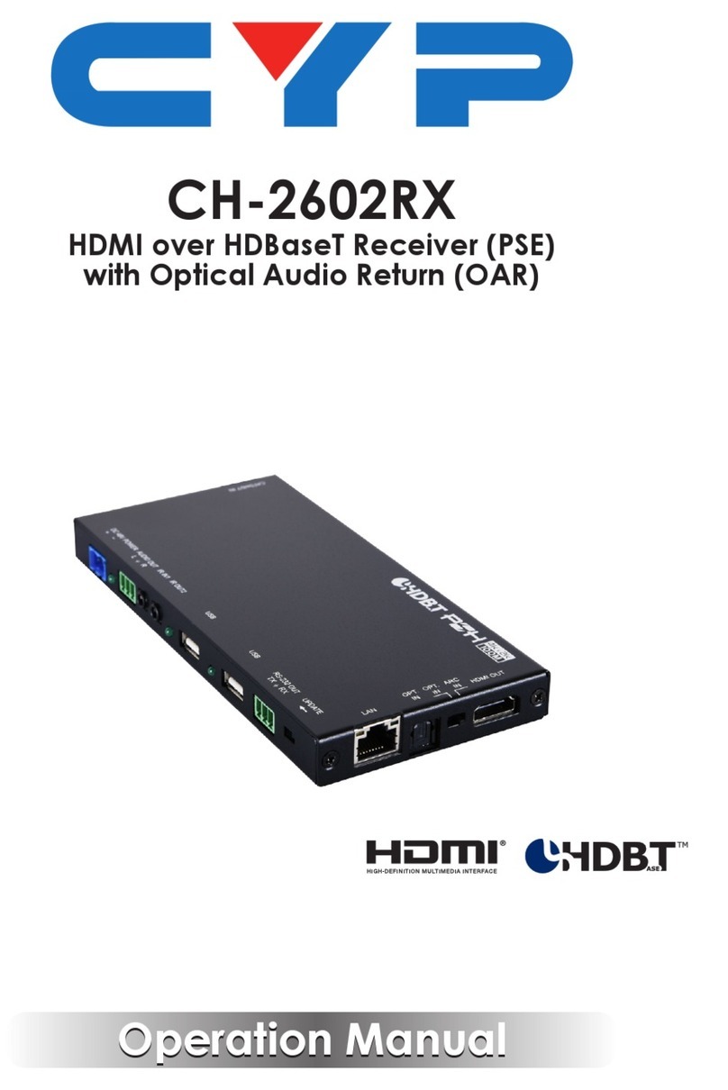
CYP CPOWER-80W User manual

CPOWER-80W
Adjustable DC Power Supply with 8 Outputs
Operation Manual
Operation Manual


DISCLAIMERS
The information in this manual has been carefully checked and
is believed to be accurate. Cypress Technology assumes no
responsibility for any infringements of patents or other rights of third
parties which may result from its use.
Cypress Technology assumes no responsibility for any inaccuracies
that may be contained in this document. Cypress also makes no
commitment to update or to keep current the information contained
in this document.
Cypress Technology reserves the right to make improvements to this
document and/or product at any time and without notice.
COPYRIGHT NOTICE
No part of this document may be reproduced, transmitted,
transcribed, stored in a retrieval system, or any of its part translated
into any language or computer le, in any form or by any means—
electronic, mechanical, magnetic, optical, chemical, manual, or
otherwise—without express written permission and consent from
Cypress Technology.
© Copyright 2012 by Cypress Technology.
All Rights Reserved.
TRADEMARK ACKNOWLEDGMENTS
All products or service names mentioned in this document may be
trademarks of the companies with which they are associated.

SAFETY PRECAUTIONS
Please read all instructions before attempting to unpack, install or
operate this equipment and before connecting the power supply.
Please keep the following in mind as you unpack and install this
equipment:
• Always follow basic safety precautions to reduce the risk of re,
electrical shock and injury to persons.
• To prevent re or shock hazard, do not expose the unit to rain,
moisture or install this product near water.
• Never spill liquid of any kind on or into this product.
• Never push an object of any kind into this product through any
openings or empty slots in the unit, as you may damage parts
inside the unit.
• Do not attach the power supply cabling to building surfaces.
• Use only the supplied power supply unit (PSU). Do not use the PSU
if it is damaged.
• Do not allow anything to rest on the power cabling or allow any
weight to be placed upon it or any person walk on it.
• To protect the unit from overheating, do not block any vents or
openings in the unit housing that provide ventilation and allow for
sufcient space for air to circulate around the unit.
REVISION HISTORY
VERSION NO. DATE DD/MM/YY SUMMARY OF CHANGE
VR0 30/08/13 Preliminary Release
VS1 28/10/13 Updated text/diagrams

CONTENTS
1. Introduction............................................ 1
2. Applications........................................... 1
3. Package Contents ................................ 1
4. System Requirements............................ 1
5. Features.................................................. 2
6. Operation Controls and Functions....... 3
6.1 Front Panel.........................................3
6.2 Rear Panel .........................................4
6.3 DC Power Cable...............................4
6.4 OLED Functions .................................5
6.5 RS-232 Protocols ................................5
6.6 RS-232 Commands............................6
7. Connection Diagram ............................ 8
8. Specications ........................................ 9

1
1. INTRODUCTION
The Adjustable DC Power Supply is an 8-way DC power splitter which
can distribute electrical power up to 8 devices (10.2 volt/3.2 amp
each port) with overall power consumption of 80 watts over Terminal
Block (3.5 mm, 2 poles). Ideal for professional applications, this
device provides smart control over each individual port and supports
adjustable voltage control and On/Off switching functions. It can be
controlled through on-panel buttons or via RS-232 commands. It also
comes with an OLED display which can show the status of all ports or
data for a single port.
2. APPLICATIONS
• Installation usage
• Control Room
• Exhibition Hall
• Outdoor activities exhibition
3. PACKAGE CONTENTS
• Adjustable DC Power Supply with 8 Outputs
• 8×Screw Type, 3.5mm, 2-pole Terminal Block
• 4×DC Lock Cable
• 2×Rack Ear
• 12V DC Power Supply Adaptor
• 1×Power Cord
• Operation Manual
4. SYSTEM REQUIREMENTS
Up to 8 devices that require power supply, connect with professional
3.5mm Terminal Blocks.

2
5. FEATURES
• Power management system that can provide voltage-
controlled current on each port, with the ability to show real-time
measurement results on the built-in OLED screen
• PC software application with the capability of collecting voltage
current variation data in time and using RS-232 protocols it can
create tables and charts of historic data
• Supports adjustment of voltage and current to allow the maximum
usage on each channel
• Supports 12 V/6.67 A power input
• Supports overall power consumption up to 80 watts
• Supports up to 8 power outputs with professional pluggable 2-pole
3.5mm Terminal Blocks

3
6. OPERATION CONTROLS AND FUNCTIONS
6.1 Front Panel
8 ADJUSTABLE DC POWER SUPPLY
12345678
ON
OFF
O.C
POWER CONTROL
RETURN CH/- CH/+ENTER/
INFO
654321
1OLED: Display each output, voltage and current value the selected
setting information.
2RETURN Button: Press to select the Function selection menu, the
OLED will display the model number and the Selection function.
Press '−/+' to display the available functions (please see section 6.5
for details).
Return to a previous selection or back to main page where the
OLED display will show the status of each output ports Voltage/
Current.
8 ADJUSTABLE DC POWER SUPPLY
12345678
ON
OFF
O.C
POWER CONTROL
RETURN CH/- CH/+ENTER/
INFO
3 CH/− or CH/+ Buttons: When in the function selection menu, press
to cycle through and view all the available functions.
In the main menu page, press to select the Channel and Press
'ENTER' to check the values for that channel.
Once entered press 'CH/+' or 'CH/−' to increase/decrease the
Voltage values (between 3.2 V~10.2 V) and press 'ENTER' again to
enter the Current Limit page, press 'CH/+' or 'CH/-' to increase/
decrease the Current values between 0.10 A~3.20 A) then press
'RETURN' to exit the setting.
4ENTER/INFO Button: When in the main page press 'ENTER' to show
the current total watts in use, press it again in sequence to display
each Channel's power consumption / voltage / current values.
5POWER CONTROL 1~8 Switch and LEDs: Each switch and LED
represents a power channel, when switched to ON the LED will illuminate
in green provide power to that channel. When switched to OFF the
LED will not illuminate and the corresponding output port will not output
power.

4
6POWER ON/OFF Button and LED: Press to power the unit ON or to set
it to standby mode. The LED will illuminate in green when powered
ON or red when in standby mode. When any of the channels is
Over Current, the LED will be ash red and the OLED screen will
display a warning sign.
6.2 Rear Panel
DC 12V
8765
POWER OUT
4321 SERVICE
RS232
-
+
-
+
-
+
-
+
-
+
-
+
-
+
-
+
1 2 3 4
1DC 12V: Connect the 12V DC power supply included in the
package to the unit and plug the adaptor with its power cord into
an AC wall outlet.
2POWER OUT 1~8: Connect power cables to the supplied 3.5mm
2-pole Terminal Blocks. Maximum of up to 8 devices.
3SERVICE: Reserved for manufacturer use only.
4RS-232: Connect with a D-Sub 9pin cable to a a PC/laptop for RS-
232 control of this system.
6.3 DC Power Cable
Note: The conductor with writing is connected to the outer part of
the power connector, the conductor without is the inner part of the
connector.

5
6.4 OLED Functions
VOL Alert TH CH1~8 Vtarget-Vout 0~4.0V
(0.5V a scale)
Erase Record CH1~8 Conrm/Cancel
Record Setting CH1~8 Interval 0.1 ~ 60 Sec. Switch
ON/OFF
Timeout Setting 5~30sec (5sec a
scale)/never
F/W Version x.xx.xx
6.5 RS-232 Protocols
CPOWER-80W
►
◄
REMOTE CONTROL
PIN Assignment PIN Assignment
1 NC 1 NC
2Tx 2Rx
3Rx 3Tx
4 NC 4 NC
5 GND 5 GND
6 NC 6 NC
7 NC 7 NC
8 NC 8 NC
9 NC 9 NC
Baud Rate: 115200 bps
Data Bit: 8-bit
Parity: None
Stop Bit: 1-bit
Flow Control: None

6
6.6 RS-232 Commands
COMMAND DESCRIPTION
help Show All Commands
parareset Reset Parameters to Default
stat Y Show Channel's Current Status
Y=0:All channels, 1~8: Channel 1~8
vout Y xx.x* Set Output Voltage
Y=0 means all channels
Y=1~8 means channel 1~8
xx.x=3.2~5.0(0.1/scale) or 5.2 ~ 10.2(0.2/scale)
Iout Y x.x* Set Current Limit
Y=0 means all channels
Y=1~8 means channel 1~8
x.x=0.1~3.2
power xxx* Set Power Mode
xxx= on, off or sta (status)
valert Y x.x* Set voltage alert threshold
Y=0:All channels, 1~8: Channel 1~8,
x.x=0~1(0.1/scale)
recordintv Y x* Set Interval Timing between current output
setting and current voltage (in second)
Y=0 means all channels
Y=1~8 meanscChannel 1~8
x= 0.1, 0.2, 0.5, 1, 2, 3, 4, 5, 10, 15, 20, 25, 30,
40, 50 or 60

7
COMMAND DESCRIPTION
recordswit Y xxx* Record Current Output Voltage
Y=0 means all channels
Y=1~8 means channel 1~8
xxx=on, off or sta (status)
recorderas Y Erase Record Data
Y=0 means all channels
Y=1~8 means channel 1~8
timeout x* Set Timeout on OLED's menu mode (in
second)
x=0, 5, 10, 15, 20, 25 or 30
version Show Firmware version
powerinfo Show the Information of input, output and
total power
Note:
1. All RS-232 commands will not execute unless followed by a
carriage return. Commands are case-sensitive.
2. Items in brackets (*) mean the status of a command setting can
be checked by using a "sta" command. For example: To check
the Voltage alert threshold for channel 1 the command would be
"Valert 1 sta".

8
7. CONNECTION DIAGRAM
DC 12V
8765
POWER OUT
4321 SERVICE
RS232
-
+
-
+
-
+
-
+
-
+
-
+
-
+
-
+
Devices to be Powered (DC)
(HDMI Splitters/Switchers/Extenders etc.)
PC/Laptop
Power Supply
RS-232 Cable

9
8. SPECIFICATIONS
Output Ports 8×3.5mm, 2-pole Terminal Block
Input Power 12 V/6.67 A
Output Voltage 3.20~10.2 V
Output Current 0.10~3.20 A
ESD Protection Human body model:
±8 kV (air-gap discharge)
±4 kV (contact discharge)
Dimensions 340 mm (W)×111 mm (D)×30(H)
Weight 935 g
Chassis Material Metal
Silkscreen Color Black
Operating Temperature 0˚C~40˚C / 32˚F ~ 104˚F
Storage temperature -20˚C~60˚C / -4˚F ~ 140˚F
Relative Humidity 20~90% RH (no condensation)
Power Consumption 80W (Max)


Home page: http://www.cypress.com.tw
CYPRESS TECHNOLOGY CO., LTD
20121225 MPM-CPOER80W
Other manuals for CPOWER-80W
1
Table of contents
Other CYP Power Supply manuals