Cypress Diagnostics CYANExpert 130 User manual


Layout 20130101
www.diagnostics.be
ISO 9001:2008
ISO 13485:2003
CYANExpert 130
User Manual
For a clear and precise diagnose
CY008
English

INDEX
CYANExpert 130 User Manual Rev.01, Sept 2013 Page 1
TABLE OF CONTENTS
Chapter 01 INSTALLATION
Chapter 02 GENERAL DESCRIPTION
Chapter 03 SOFTWARE DESCRIPTION
Chapter 04 DAILY ROUTINE
Chapter 05 METHODOLOGY
Chapter 06 CALIBRATION CURVES
Chapter 07 MAINTENANCE
Chapter 08 FORMULAS AND CALCULATION MODELS
Chapter 09 ERROR SIGNALING AND TROUBLESHOOTING
Chapter 10 PACKING LIST
Chapter 11 DIAGNOSTIC PROGRAM

Chapter 01 - INSTALLATION
CYANExpert 130 User Manual Rev.02, Feb 2014 Chapter 1, Page 1
CHAPTER 01 - INSTALLATION
1.1 UNPACKING .........................................................................................................................................2
1.2 INSTALLATION.....................................................................................................................................4
1.2.1 LOCATION SPECIFICATION ...............................................................................................................................................4
1.2.2 ELECTRIC CURRENT REQUIREMENTS................................................................................................................................4
1.2.3 LABEL AND SYMBOLS .......................................................................................................................................................5
1.2.3.1 Label .........................................................................................................................................................................................5
1.2.3.2 Symbols ...................................................................................................................................................................................5
1.2.4 REGULATORY COMPLIANCE..............................................................................................................................................6
1.2.5 LIMITATIONS OF USE.........................................................................................................................................................6
1.2.6 BARCODE READER.............................................................................................................................................................6
1.2.7 CONSUMABLES AND ACCESSORIES SUBJECTED TO WEAR AND USE ..............................................................................6
1.3 BRIEF INSTALLATION PROCEDURE.................................................................................................8
1.3.1 SOFTWARE INSTALLATION................................................................................................................................................8
1.3.2 ACCESSORIES CONNECTIONS...........................................................................................................................................8
1.3.2.1 Power supply .........................................................................................................................................................................8
1.3.2.2 Computer connection.........................................................................................................................................................8
1.3.2.3 Hydraulic Connections .......................................................................................................................................................9
1.3.2.4 Pump Tube Connection.................................................................................................................................................. 10
1.3.2.5 Sample Probe Installation............................................................................................................................................... 11
1.3.2.6 Reaction Rack Installation............................................................................................................................................... 12
1.3.3 CHECKING THE ANALYSER ..............................................................................................................................................13
1.3.4 ADAPTATION OF THE SYSTEM TO THE CUSTOMER........................................................................................................13
1.3.4.1 Install additional methods (if necessary)................................................................................................................... 13
1.3.4.2 Configure the user specific options ............................................................................................................................ 13
1.3.4.3 Create user profiles........................................................................................................................................................... 13
1.3.5 GIVE EXTENSIVE EXPLANATION TO THE USER!...............................................................................................................13

Chapter 01 - INSTALLATION
CYANExpert 130 User Manual Rev.02, Feb 2014 Chapter 1, Page 2
1.1 UNPACKING
The CYANExpert 130 is packed and delivered in a wooden crate with an adjoining cardboard box. The wooden crate
contains the analyzer itself. The accessories are packed in the cardboard box. The packing has been expressly studied
and designed to insure maximum protection of the contents during shipping and handling. It is therefore extremely
important that the crate and box are carefully examined upon delivery in order to assure their integrity. Special
attention should be dedicated to examine the colour of the “Shock Watch” label, glued on the wooden crate. It has to
be ‘white’. A ‘red’ “Shock Watch” label indicates that the crate has experienced some sort of ‘shock’ during handling,
transport and/or delivery. This fact must be noted by the courier on the delivery note, as must any and all visible
external damage (for example: holes, dents, rips or tears, water marks, etc.) evident at the moment of delivery. This
will simplify matters in the event of any future claims for damages.
NOTE: ONCE THE CARRIER HAS TAKEN POSSESSION OF THE SYSTEM FOR TRANSPORTATION FROM THE
FACTORY, THE CARRIER ASSUMES TOTAL RESPONSABILITY UNTIL ITS DELIVERY. ALL CLAIMS FOR
DAMAGE DUE TO TRANSPORTATION MUST BE FILED AGAINST THE CARRIER AS SOON AS THESE
DAMAGES ARE NOTICED.
Open the crate/box from the top and very carefully take out:
-The instrument;
-The accessories.
NOTE: MAKE SURE THAT THE UNPACKING IS CARRIED OUT BY TWO PEOPLE. Do not discard the delivery
crate/box or the packing material until the correct functioning of the instrument has been verified.
Make sure that the serial number on the delivery note/packing list corresponds to the serial number on the back label
of the instrument:

Chapter 01 - INSTALLATION
CYANExpert 130 User Manual Rev.02, Feb 2014 Chapter 1, Page 3
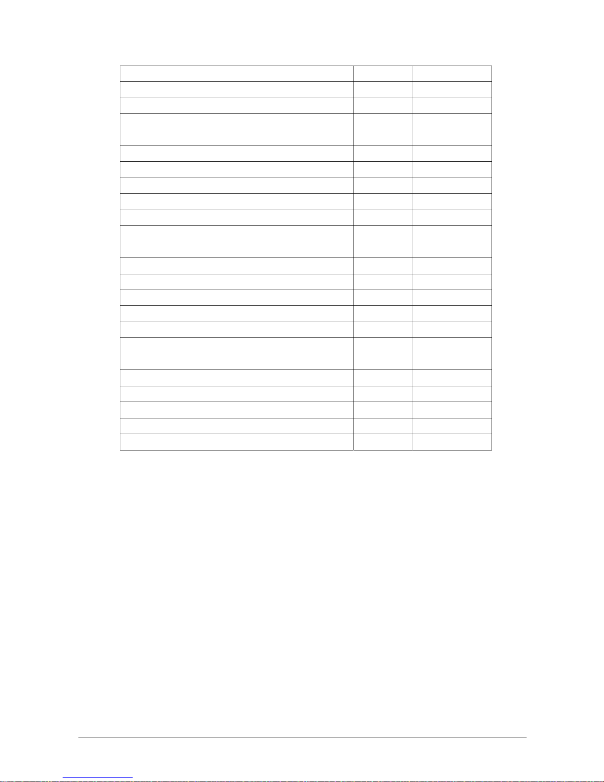
Upon arrival of the box, take out the delivery note and make sure that all the items of the following packing list are
included in the crate and are undamaged:
Code Description Quantity
CY008 CYANExpert 130 Analyzer 1
CY008-BC Barcode reader kit (optional)
- CYANExpert 130 Software 1
- User manual 1
CY008-C08 Reaction tray cover (delivered on the instrument) 1
CY008-C09 Reaction tray without cover (delivered on the instrument) 1
CY008-S33 Sampling probe assembly (delivered on the instrument) 1
CY008-C03 Reaction cuvettes cover 1
CY008-S80 Special key for probe tightening 1
CY008-S08 Power cord 1
CY008-S09A Fuse 6,3 A-T 5x20 2
CY008-S78 Interconnecting serial cable PC analytical module 1
USB-RS232 converter cable with software 1
CY008-C02 Rack for primary tubes (universal) and 3 mL cups 4
CY008-C04 Rack for predilution cups (0.8 mL cups) (optional)
CY008-C22A Pack of 200 short cups (1 mL) – Calibrator and Control cups 1
CY008-C28 Pack of 1000 sample cups for primary tube rack (3 ml) 1
CY008-C21A Pack of 200 predilution cups (0.8 mL) 1
CY008-C25 Pack of reagent container 35 ml + caps (12 pcs) 1
CY008-C26 Pack of reagent containers 6 ml + caps (12 pcs) 1
CY008-S76 Bottle level sensor assembly 4
CY008-S77 Bottles 2 L 4
CY008-S90 Bottles connecting cable 1
CY008-C17 Inlet tubes kit (4 pcs) 1
Waste tubes kit (3 pcs) 1
CY008-C27 Reaction cuvettes (20 pcs per sector/rack) – 6 sectors 1
CY008-WS-I Rinse solution (1 x 50 ml) 1
CY008-WS-III Cleaning solution (5 x 30 ml) 1
CY008- WS-IV Acid solution (5 x 25 ml) 1
Remove the adhesive tape from the cover of the samples and reagents housing, from the front panels and from the
samples and reagents racks.
Before connecting the CYANExpert 130, remove the protective packing material around the sampling arm and under
the washing station.
Warning: In the event that it is necessary to repack any or all of the delivered item(s), the following procedures must
be carefully followed:
Reposition the protective packing material around the sampling arm and under the washing station.
Be very careful not to bend the washing station cannulas when repositioning the protective packing material.
Tape down (using masking tape if possible) the main cover of the samples and reagents housing, the front
panels and the sample and reagent racks.
Remove the probe from the sampling arm and place it inside a primary tube. Then cap the tube and tape the
tube down.
Fill the empty spaces around the accessories packed in the crate using “pluriballs” or other suitable packing
material.

Chapter 01 - INSTALLATION
CYANExpert 130 User Manual Rev.02, Feb 2014 Chapter 1, Page 4
1.2 INSTALLATION
The CYANExpert 130 should only be installed by a qualified service engineer, who has been authorised and trained
to do so. During its installation the system must be checked once again to ensure correct functioning. The persons
who are required to operate the CYANExpert 130 system must have received adequate training. This should also
include the "know-how" of the normal maintenance of the instrument. A description of the maintenance can be
found in Chapter 7 of this manual.
The CYANExpert 130 is a complex system, and it is therefore extremely important that it is correctly installed
in order to fully guarantee the good performance. If the installation and usage directions, given in this
manual, are not followed correctly and/or safety indications are not respected, Cypress Diagnostics cannot
guarantee correct functioning of the instrument. Besides, misuse of the instrument could compromise the
safety of the operator.
1.2.1 LOCATION SPECIFICATION
Verify that the CYANExpert 130 is not exposed to direct sunlight, draughts, dust or strong magnetic fields. In addition,
please take note of the following conditions required for the location of the installation:
USE In a covered and dry place
DEGREE OF POLLUTION* 2
INSULATION CLASS* I
INSTALLATION CATEGORY* II
TEMPERATURE Between 18 - 32°C for use
Between 5 - 50°C for storage
HUMIDIT
Y
20% - 85%
ALTITUDE Max 3000 m
LOCATION Shelf or table with a minimum surface of 70 x 60 cm, stable and free of
vibration
VENTILATION
Leave a minimum distance of 10 cm around the instrument to permit
air circulation. Make sure that the fan (situated under the reagent
compartment) is not blocked by any object.
* Isolation and Safety Standards for Electronic Instruments
1.2.2 ELECTRIC CURRENT REQUIREMENTS
The power voltages that are suited for the instrument are indicated on the back label.
It must be plugged into a plug of the correct voltage.
VOLTAGE 100 - 230 VAC 47/63 Hz ± 10%
FUSES 5 x 20 6.3 A/
T
Note: It is advisable to maintain maximum stability of the electrical current in the laboratory. Where this is not
possible or ascertainable, use of the following supplementary devices is recommended:
1. Electronic Stabilizer
This is used to stabilize the electric voltage in the laboratory. Any stabilizer, currently available on the market,
with a power potential of at least 0.5 KW can be used.
2. No Break module UPS - (Uninterrupted Power Supply)
This module provides two important functions:
- Stabilizes the main-line power
- Supplies current to the instrument in case of a main-line power failure

Chapter 01 - INSTALLATION
CYANExpert 130 User Manual Rev.02, Feb 2014 Chapter 1, Page 5
1.2.3 LABEL AND SYMBOLS
1.2.3.1 Label
The following LABEL is found at the back of the instrument.
CAUTION
SERVICE PERSONNEL
REFER SERVING TO QUALIFIED
DO NOT REMOVE BACK PANEL.
TO PREVENT ELECTRIC SHOCK
NO USER-SERVICEABLE PARTS INSIDE.
NOTE: The protection cover of the instrument must never be opened without having first switched the
instrument off and disconnected the electricity cable.
The maintenance and cleaning procedures found in chapter 7 of this manual must be respected at all times.
Remember to follow the decontamination procedure when required before maintenance operation (chapter 7).
1.2.3.2 Symbols
Symbol Explanation
Attention:
Read the instructions in the user manual.
Biological hazard:
Carefully manipulate all the consumables and the wastes produced during the
analysis routines. Use appropriate protective garment. Disposal of wastes must
be done in compliance with applicable regulation. It is recommended to
periodically check the level in the waste container, in order to avoid overflow.
Ground terminal (conductor)
Wash bottles connection
I Rinse Solution
II Distilled water
III Cleaning Solution
IV Acid Solution
Stand-by button

Chapter 01 - INSTALLATION
CYANExpert 130 User Manual Rev.02, Feb 2014 Chapter 1, Page 6
Buzzer off button
Barcode reader button
1.2.4 REGULATORY COMPLIANCE
The CYANExpert 130 complies with European Directive 98/79/CE for
In Vitro
Diagnostic Devices.
1.2.5 LIMITATIONS OF USE
The CYANExpert 130 cannot be used by blind operators because the user interface with the system requires a
monitor.
Furthermore the CYANExpert 130 must be used with particular caution by color blind operators because the graphic
interface displays different colors with different meaning.
1.2.6 BARCODE READER
A barcode reader can be optionally installed on the CYANExpert 130. The barcode reader has a laser micro-scanner
classified as Class II laser device. It is compliant with applicable safety regulations.
WARNING: ALWAYS TURN OFF THE INSTRUMENT before removal of those panels and covers that protect from any
interference and/or exposure to the laser beam active during sample/reagent identification.
1.2.7 CONSUMABLES AND ACCESSORIES SUBJECTED TO WEAR AND USE
These consumables and accessories are not included in the warranty.
Description Quantity
(Pieces) Code
Reagents containers - 35 mL + caps 12 CY008-C25
Reagents containers - 6 mL + caps 12 CY008-C26
Reagent tray cover 1 CY008-C08
Reagent tray (without cover) 1 CY008-C09
Reaction cuvettes (20 pcs per sector/rack) 6 CY008-C27
Reaction cuvettes cover 1 CY008-C03
Rack for primary tubes and 3 mL cups 1 CY008-C02
Rack for predilution cups (0.8 mL cups) 1 CY008-C04
Predilution cups (0.8 mL) 1000 CY008-C21
Sample cups for primary tube rack (3 mL) 1000 CY008-C28

Chapter 01 - INSTALLATION
CYANExpert 130 User Manual Rev.02, Feb 2014 Chapter 1, Page 7
Short cups – Calibrator and control cups (1 mL) 1000 CY008-C22
Tubing kit for peristaltic pump 2 CY008-C10
Tubing kit – complete 1 CY008-C11
Sampling probe (internal cannula) 1 CY008-S30
Sampling probe assembly 1 CY008-S33
Rinse solution (1 x 50 mL) 1 CY008-WS-I
Acid solution (5 x 25 mL) 1 CY008-WS-III
Cleaning solution (5 x 30 mL) 1 CY008-WS-IV
Drying pad 1 CY008-C01
Halogen lamp (6 V - 10 W) 1 CY008-C20
Fuses 6,3 A-T (5x20) 10 CY008-S09
Inlet/outlet fitting for washing solutions 1 CY008-S75
Bottle 2 L 1 CY008-S77
Bottle level sensor assembly 1 CY008-S76
Washing station, first or second cannulas (A) 1 CY008-S46
Washing station, third cannula (B) 1 CY008-S47
Washing station, fourth cannula (C) 1 CY008-S48
Washing station, fifth cannula without drying pad (D) 1 CY008-S49
Diluter Micro-Pump assembly 1 CY008-S40
Micro-Pump assembly (μP 2 to 5) 1 CY008-S54
Air Micro-Pump assembly (μP 6) 1 CY008-S55
Solenoid Valve –2 way 1 CY008-S58
Solenoid Valve –3 way 1 CY008-S59
Interferential filters kit (Stablife) 1 CY008-S64

Chapter 01 - INSTALLATION
CYANExpert 130 User Manual Rev.02, Feb 2014 Chapter 1, Page 8
1.3 BRIEF INSTALLATION PROCEDURE
The installation of the CYANExpert 130 instrument should be performed by a qualified service engineer!
1.3.1 SOFTWARE INSTALLATION
By service engineer
1.3.2 ACCESSORIES CONNECTIONS
Please follow these instructions carefully in order not to damage any parts of the instruments.
1.3.2.1 Power supply
Connect the power cord to a grounded AC wall outlet, preferably one that is not shared with other electric
appliances and with low fluctuation of line voltage compared to the standard voltage specified (10-15%).
If the AC wall outlet is not properly grounded, please connect a ground or earth wire to the mounting screw or
ground terminal (conductor) on the case (see picture above on the right) to ensure safety.
Keep the instrument away from other appliances that generate high frequency electrical noises (eg radiological
instruments).
Note:
The instrument can work at 100 – 230 V. The correct voltage setting is automatically detected and selected by the
apparatus.
!! WARNING !! Fire hazard. For continued protection replace only with the same type and rating of fuses! Fuses
6.3 A/T – 5 X20 ~100-230 V. Always disconnect power cord before opening.
1.3.2.2 Computer connection
The instrument and Personal Computer are connected by a serial RS232 cable (CY008-S78), which provides the
hardware support for the communication.
1.3.2.3
Mounting screw
or ground terminal

Chapter 01 - INSTALLATION
CYANExpert 130 User Manual Rev.02, Feb 2014 Chapter 1, Page 9
1.3.2.3 Hydraulic Connections
The instrument uses cleaning solution, acid solution and distilled water for cleaning the reaction cuvettes; and rinse
solution for cleaning the sampling probe and determining the cuvette blank level (WBL).
For connecting these solutions, there are four inlets on the side of the instrument identified by roman numbers as
specified here below (see middle picture).
IRinse solution (CY008-WS-I) green color
II Distilled water yellow color
III Cleaning solution (CY008-WS-III) blue color
IV Acid solution (CY008-WS-IV) red color
Connect the bottles interconnecting cable between the four wash solution bottles and the instrument. This way the
level of the solutions can be measured and controlled. Please ensure to connect the correct cable to the correct wash
bottle and sensor (roman numbers) (see picture above on left).
The waste hydraulic lines are located on the back side of the instruments (see picture above on right). Put the three
different waste lines into a waste container, separately or all together, according to the costumers’ site waste
legislation and regulation. Make sure the waste container(s) is standing below the tubes outlet on the analyzer.
1. Biological hazard or biohazard: sample and reagents Silicon tubing Øi2-Øe4
2. Limited biohazard: minimal contact with sample and reagents Silicon tubing Øi2-Øe4
3. Nobiohazard PVCtubingØi2-Øe6
1 2 3
Bottles interconnecting
cable

Chapter 01 - INSTALLATION
CYANExpert 130 User Manual Rev.02, Feb 2014 Chapter 1, Page 10
1.3.2.4 Pump Tube Connection
Upon delivery, the pump is in a ‘relaxed’ state: the tube is loose. To make it operational, proceed as follows:
1. Open the peristaltic pumps’ door at the side of the instrument.
2. Hook the hinged guide (picture above), paying attention to the correct position of the tubes. These should
be in the two guides of the holder (picture below).
3. Manually rotate clockwise the peristaltic pump rotor and check to make sure that the tubes are correctly
positioned insides the guides.
4. Close the peristaltic pumps’ door.
Peristaltic
pump door
Unhooked
hinged guide
Two
id
Two guides
Hooked
hinged guide

Chapter 01 - INSTALLATION
CYANExpert 130 User Manual Rev.02, Feb 2014 Chapter 1, Page 11
1.3.2.5 Sample Probe Installation
The sample needle is delivered in a small tube to protect the level sensor device. To install this needle, please
proceed as follows:
1. Carefully take out the probe from its protection tube. Do not touch the tip of the probe. This way the liquid
level sensor can be damaged.
2. Please insert (straight!) the sample probe to the probe holder of the sampling arm and slowly rotate
(counter clockwise) the sample probe ring nut (without applying any force!).
3. Take the special screwdriver (dynamometric key), delivered with the instrument, and place the head
around the ring nut of the sample probe (see figure below). Screw (counter clockwise) with the
dynamometric key until the correct torque is reached and the key spins freely around the sample probe. You
will hear a clicking noise when it is screwed completely, do NOT try to screw it any further.
4. Remove the dynamometric key.
5. Open the “Diagnostic” program; select "Miscellaneous” folder and request an Instrument General Reset. Wait
until the general reset procedure has been completed; make sure that all the Home Sensors of the Sampling
Arm (Vertical and Horizontal), Reactions, Reagents and Samples Plates light up in green.
Sample probe
Sampling arm
head
Probe holder
CCW
Sampling probe
ring nut
Dynamometric key
CC
W

Chapter 01 - INSTALLATION
CYANExpert 130 User Manual Rev.02, Feb 2014 Chapter 1, Page 12
Pay attention: The needle should be perfectly straight (90° angle to the analyzers platform) onto the sampling arm
and perfectly above the washing well, when it is in its initial position (general reset). If the probe is not positioned
correctly, the level sensor can be damaged once the analyzer is running. If case of doubt about the correct
installation or centering; please always contact your service engineer.
1.3.2.6 Reaction Rack Installation
The analyzer is delivered with six reaction racks (20 reaction cuvettes per rack). These should be placed in the outer
circle of the plate. To install them, please proceed as follows:
1. Turn on the analyzer and wait until the instrument has reached its proper operating temperature.
2. Remove the black reaction rack cover present on the reaction rack area.
3. Push the “load reaction rack’- replace button in the software.
4. Turn the two metal locking pins so that they are in line with the plate or screw the attachment screws.
5. Place the reaction rack in the analyzer. Always insert the racks vertically. Be especially careful not to touch
the external surface of the reaction cuvettes with your fingers. Also check no packaging material
(isomo) is attached to the cuvettes. This latter and fingerprints will have a bad influence on the
measurements.
6. Turn the two metal locking pins back to their original position.
7. Turn the plate by using the “load reaction rack” button in the software interface and perform the same for
the other 5 reaction racks.
Load reaction rack
button
Reaction rack cover
Metal locking pin in
line with the plate Metal locking pin in
original position

Chapter 01 - INSTALLATION
CYANExpert 130 User Manual Rev.02, Feb 2014 Chapter 1, Page 13
1.3.3 CHECKING THE ANALYSER
By service engineer
1.3.4 ADAPTATION OF THE SYSTEM TO THE CUSTOMER
1.3.4.1 Install additional methods (if necessary)
By service engineer
1.3.4.2 Configure the user specific options
- Open the CYANExpert 130 software
- Go to the menu “Parameters” and open the menu “Options” (Chapter 3).
- Indicate the following settings according to the customers’ site:
Barcode reader
Host connection
Type of default reagent container: 6 ml or 35 ml. In this menu the default container is set. The user can still
choose the other container in the menu ‘Checks’ in the submenu ‘Reagent configuration’.
Pay attention: what is programmed in the software should correspond to what is placed on the plate
manually! This is extremely important in order not to break the sample probe!
Type of default cup container: 3 ml or primary tubes. This is extremely important in order not to break
the sample probe! Primary tubes and 3 ml cups can both be placed on a sample rack for primary tubes.
Using the setting primary tubes is safe for primary tubes and 3 ml tubes; however it increases the dead
volume for the 3 ml tubes. The setting of 3 ml tubes CANNOT be used for primary tubes!
A combination of different sample cup settings is NOT possible! The user has to choose the same
option for the 4 racks!!
Automatic data deletion (number of days)
In order to protect the sampling probe and its level sensor, always make sure the programmed type of sample
cups and reagent containers in the option folder and on the software configuration of the plate are
completely the same as the real cups and containers putted on the plate by the user! This should be made
very clear to the user, so please repeat it several times, theoretically and practically!
1.3.4.3 Create user profiles
Give the user(s) restricted access by creating user profiles.
The first time they login, they have the opportunity to change the password to their choice.
1.3.5 GIVE EXTENSIVE EXPLANATION TO THE USER!
Explain the procedure for routine analysis (patient entries, patient results, calibration results, QC-results – for more
information see quick user manual). Teach them how to run the tests and check the results. Always do some tests
together with the customer in order to teach them how to use the CYANExpert 130!
In order to protect the sampling probe and its level sensor, always make sure the programmed type of sample
cups and reagent containers in the option folder and on the software configuration of the plate are
completely the same as the real cups and containers put on the plate by the user! This should be made very
clear to the user, so please repeat it several times, theoretically and practically!

Chapter 02 - GENERAL DESCRIPTION
CYANExpert 130 User Manual Rev.02, Feb 2014 Chapter 2, Page 1
CHAPTER 02 – GENERAL DESCRIPTION
2.1INTENDED USE AND SYSTEM DESCRIPTION...........................................................................2
2.2MAIN COMPONENTS and ANALYSE CYCLES...........................................................................3
2.2.1ANALYTICAL PLATE...................................................................................................................................3
2.2.2WASHING WELL........................................................................................................................................4
2.2.3SAMPLING SYSTEM ...................................................................................................................................4
2.2.4SAMPLING ARM .........................................................................................................................................5
2.2.5WASHING STATION...................................................................................................................................7
2.2.6INCUBATOR................................................................................................................................................8
2.2.7PERISTALTIC PUMP ...................................................................................................................................8
2.2.8PHOTOMETRIC SYSTEM ............................................................................................................................8
2.2.9FRONT PANEL INDICATION BUTTONS .......................................................................................................8
2.2.10BARCODE READER ....................................................................................................................................8
2.3SOFTWARE AND COMPUTER SPECIFICATIONS ......................................................................9
2.4TECHNICAL & OPERATIVE FEATURES........................................................................................9
2.5DIMENSION, WEIGHT and ENVIRONMENT ............................................................................10
2.6INSTALLATION SPECIFICATIONS .............................................................................................10

Chapter 02 - GENERAL DESCRIPTION
CYANExpert 130 User Manual Rev.02, Feb 2014 Chapter 2, Page 2
2.1 INTENDED USE AND SYSTEM DESCRIPTION
The CYANExpert 130 is a random access, computer controlled, bench top, clinical analysis instrument. The system
can perform 138 tests per hour and has a machine cycle of 26 seconds. Its execution time ranges from a minimum of
18 seconds to a maximum of 1032 seconds, depending on the analysis method chosen.
At installation of the system, the service engineer must configure the system based on the specific needs of the
user. The service engineer must program the chemistry method parameters, the reagents configuration racks, the
normal value ranges for samples, calibrators and controls, the options, the print report and make user accounts.
The daily routine analysis can be carried out according to patient sample arrival in a sequential and continuous,
non-stop manner.
The work list is organized by loading racks that can hold up to 8 patient samples per rack. Racks can be loaded
continuously. The racks can accommodate primary tubes or 3mL cups. Racks for predilution cups (0.8 mL) are
optional. The barcode reader for primary tubes and reagent containers is an optional feature.
If the analytical unit (and the computer) is turned on, the instrument goes in “Stand-by” status:
The lamp is supplied with low voltage power (1.2 V)
The reaction plate is maintained at 37°C
The electronic components are turned on
The sampling arm pre-heater remains turned off
The "Stand-by" light, placed on the front panel, will flash until the reaction plate reaches a temperature of 37°C.
Once it is reached, the "Stand-by" light will stop flashing and will remain constantly lit.
When any system function or measurement is launched:
The lamp is supplied with regular voltage power (6.0 V)
The sampling arm pre-heater will warm up
In the case of system failure or malfunction, the light, situated on the front panel of the instrument, will light up red.
When starting up the computer, the software should automatically open. Otherwise, double click on the
“CYANExpert 130" icon on the computer desktop. The login menu will appear.
NOTE:
The CYANExpert 130 is a system that allows configuration with different reagents selected by the customer in order
to fit his needs. Upon delivery, the instrument is configured for the validated biochemistry kits of Cypress
Diagnostics. In order to assure the analytical performances of the system “instrument + reagents”, we strongly
recommend only to use reagents, controls and calibrators validated on the CYANExpert 130.

Chapter 02 - GENERAL DESCRIPTION
CYANExpert 130 User Manual Rev.02, Feb 2014 Chapter 2, Page 3
2.2 MAIN COMPONENTS and ANALYSE CYCLES
2.2.1 ANALYTICAL PLATE
The analytical plate is the main movable part of the analyser and is built up out of three plates, each separately
moving from each other due to three different axes.
From the outer to the inner circle it contains:
The REACTION PLATE, provided with 6 semi-disposable racks of 20 reaction cuvettes, for a total of 120
cuvettes.
The SAMPLE PLATE, provided with 4 sample racks of 8 sample positions each, for a total of 32 samples. You
can program and use either primary tubes (universal) or 3 mL sample cups. For every sample, there is also a
position for a predilution cup (0.8 mL).
The REAGENT AND CALIBRATOR/CONTROL PLATE, provided with 12 calibrator and control positions (1 mL
cups) and 24 reagent positions. You can program and use 35 mL or 6 mL reagent containers.
A. REACTION PLATE
DESCRIPTION:
The reaction plate of the CYANExpert 130 contains 6 semi-disposable racks with 20 reaction cuvettes each.
The racks can be removed individually. However, it is recommended to replace them together.
The basic operating cycle of the reaction plate takes 26 seconds. This cycle includes the optic reading of the
cuvettes in incubation, the aspiration and dispensation of the reagents and the samples by the arm, along with the
relative positioning of the plate.
The reactions take place at 37°C. This temperature is maintained constant by a controlled heating unit placed under
the reaction plate.
REACTION PLATE CYCLE:
After reagents and samples have been placed in cuvette #1, the reaction plate will rotate 40 positions counter-
clockwise to bring this first cuvette in front of the optic system for reading with either one or two wavelengths.
The plate will then, moving clockwise, carry out all the readings of any other prepared cuvettes. After having
performed all the readings, the plate will move counter-clockwise to its initial position minus one cuvette, ready for
a new dispensing.
In this manner, the reaction cuvettes move clockwise 1 - 2 - 3 - 4 for dispensation, washing and the relative readings.
REACTION PLATE
with reaction cuvettes
CALIBRATOR/CONTROL
AND REAGENT PLATE
SAMPLE PLATE
Primar
y
tubes
3mL cups
Predilution cups
Reagent container 35
mL or 6 mL
Calibrator or control
cups (1 mL)

Chapter 02 - GENERAL DESCRIPTION
CYANExpert 130 User Manual Rev.02, Feb 2014 Chapter 2, Page 4
B. SAMPLE PLATE
DESCRIPTION:
The sample plate is provided with 4 removable racks of 8 sample positions each. This makes a total of 32 sample
positions on one cycle. Sample racks can be continuously loaded during running.
The CYANExpert 130 is delivered with 4 racks for primary tubes. They each contain 8 sample positions and 8
corresponding predilution positions. This rack can be used with primary tubes and 3 ml cups.
Pay attention!
Primary tubes dimensions: diameter from 8 to 16 mm, height from 40 to 100 mm.
Never use 1 mL cups on the primary tube rack!
Remark: The predilution position (0.8 mL cups) is only used for methods that require a predilution for all the
samples. The predilution ratio and the necessary diluent are then programmed in the method parameters menu.
Pay attention! Dilution of ‘rerun’-samples is done automatically in the reaction cuvettes and does not use these
predilution positions.
Optionally, they are racks for predilution available. These contain 25 positions for 0.8 ml cups.
This rack is used for:
-Automatic calibration dilution for multipoint calibrations (e.g. Turbidimetric measurements)
-Predilution of calibrators and controls of methods that are programmed with a predilution
-Repetition of samples for methods programmed with a predilution and for which the predilution position
on the sample rack has already been used.
The CYANExpert 130 allows to program zero, one or two predilution racks.
The predilution racks are not standardly included. They have to be ordered separately.
C. REAGENT AND CALIBRATOR/CONTROL PLATE
DESCRIPTION:
The reagent and calibrator/control plate is a non-cooled, removable tray with 24 positions for reagents (35 ml or 6
ml containers) and 12 positions for calibrators and controls (1ml cups). This tray can be easily removed for
refrigeration. During analysis, the tray must always be protected by the reagents plate cover. Only this way external
contamination can be avoided. The cover must be fixed by turning the upper black handle clockwise.
2.2.2 WASHING WELL
The washing well is the place where the washing of the sampling probe (internally and externally) with rinse
solution takes place to avoid cross-contamination between sampling.
2.2.3 SAMPLING SYSTEM
The sampling system consists of a highly precise diluter controlled by a microprocessor and has the following
specifications:
Diluter volume 550 µl
Sample volume from 2 to 99 µl with 1 µl increment
Reagent 1 volume
Reagent 2 volume
Reagent 3 volume
from 3 to 500 µl with 1 µl increment
from 3 to 330 µl with 1 µl increment
Minimum reaction volume 220 µl
Accuracy >99%
Materials in contact with the solutions
T
eflon & glass
Precision CV < 1 % at 2 l
The recommended minimum sampling volume is 3 l and 250 l for total reaction volume. There is also an
automatic wash cycle in between tests to avoid the risk of cross-contamination.
This manual suits for next models
1
Table of contents
Other Cypress Diagnostics Laboratory Equipment manuals
Popular Laboratory Equipment manuals by other brands

ESPEC
ESPEC SU Series installation guide

V&P Scientific
V&P Scientific VP 710E5 Series installation instructions

Westlab
Westlab 663-898 product manual

World Precision Instruments
World Precision Instruments KITE Care and maintenance

Westlab
Westlab 665-134 product manual

NACALAI TESQUE
NACALAI TESQUE COSMOSIL quick start guide