Noraxon Ultium 808 User manual
2D Goniometer SmartLead User Manual
1
(Rev D January 2020)
Ultium™Biomechanics
Research System
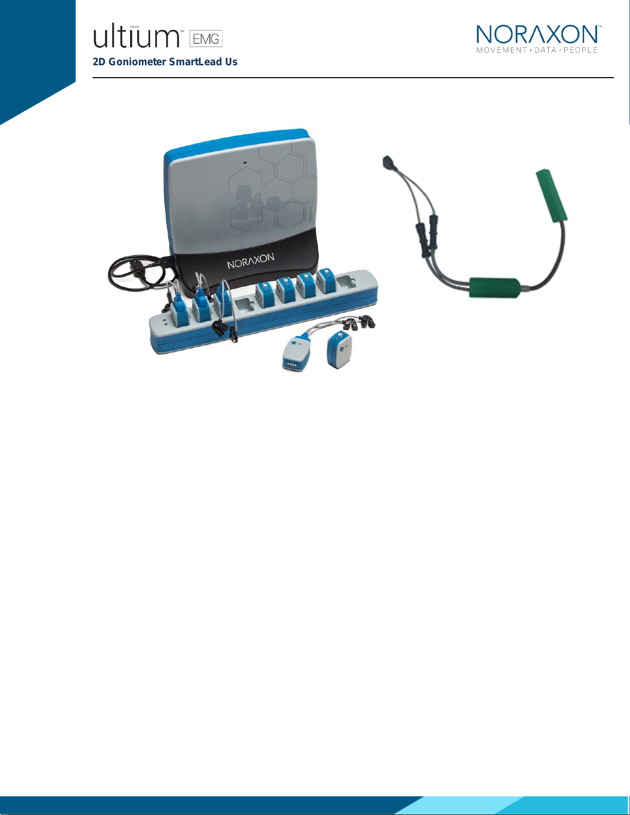
2D Goniometer SmartLead
User Manual

2D Goniometer SmartLead User Manual
2
(Rev D January 2020)
Table of Contents
1Introduction.......................................................................................................................................5
1.1 Brief Description......................................................................................................................5
1.2 Contradictions..........................................................................................................................5
2Definitions.........................................................................................................................................6
2.1 Graphic Symbols and Meaning...............................................................................................6
2.2 Glossary of Terms...................................................................................................................6
3Identification.....................................................................................................................................7
3.1 Model Designation...................................................................................................................7
3.2 Product Versions and Configurations......................................................................................7
4General Warnings and Cautions......................................................................................................8
4.1 Risks and Benefits...................................................................................................................8
4.2 Safety Information Summary...................................................................................................8
5Preparing the Product for Use .........................................................................................................9
5.1 Unpacking and Component Identification ...............................................................................9
5.2 Component Inputs, Outputs, and Indicators ...........................................................................9
5.3 Component Interconnections ................................................................................................10
5.4 Device Communication (Driver) Software Installation...........................................................11
5.5 Companion Software Installation ..........................................................................................11
5.6 Companion Software Configuration ......................................................................................11
6Pre-Use Check...............................................................................................................................15
6.1 Normal Appearance of Signals .............................................................................................15
7Operating Instructions....................................................................................................................16
7.1 Safety Information Summary.................................................................................................16
7.2 Normal Functions with Interface to a PC...............................................................................16
7.3 Exceptional Functions/Situations (error messages)..............................................................16
7.4 Shutdown after Use...............................................................................................................16
7.5 Storage and Protecting Between Usages.............................................................................16
7.6 Goniometer SmartLead and Sensor Care.............................................................................16
7.7 Goniometer Maintenance......................................................................................................18
8Cleaning.........................................................................................................................................19
8.1 Safety Precautions When Cleaning ......................................................................................19
8.2 Cleaning by Users.................................................................................................................19
9Maintenance...................................................................................................................................20
9.1 Device Software (firmware) updates.....................................................................................20
9.2 Maintenance by Qualified Individuals....................................................................................20
9.3 Companion Software Updates ..............................................................................................20
9.4 Attention ................................................................................................................................20

2D Goniometer SmartLead User Manual
3
(Rev D January 2020)
10 Troubleshooting.........................................................................................................................21
10.1 Website Link to FAQ .............................................................................................................21
11 Service and Repair....................................................................................................................22
11.1 Warranty Information.............................................................................................................22
11.2 Submitting Technical Support Requests...............................................................................22
11.3 Returning Equipment.............................................................................................................22
12 Spare Parts and Consumables .................................................................................................23
12.1 Consumable Items.................................................................................................................23
12.2 Replaceable Items.................................................................................................................23
13 Specifications of the Product.....................................................................................................24
13.1 Expected Useful Lifetime.......................................................................................................24
13.2 Technical Specifications........................................................................................................24
13.3 Environmental Conditions for Storage and Transport...........................................................24
14 Appendix A: Goniometer Specifications...................................................................................25
15 Appendix B: Application Diagrams............................................................................................26
15.1 Electrical Goniometer Theory................................................................................................27
15.2 2D Electrical Goniometer Sensor Application.......................................................................29
15.3 Sign Conventions for Selected Joints ...................................................................................37
2D Goniometer SmartLead User Manual
4
(Rev D January 2020)
- Manufacturer:
Noraxon U.S.A. Inc.
15770 North Greenway-Hayden Loop, Suite 100
Scottsdale, AZ 85260
Tel: (480) 443-3413
Fax: (480) 443-4327
Email: i[email protected]
Support Email: support@noraxon.com
Web Site: www.noraxon.com
- Authorized European Representative:
EC
REP
Advena Limited, Tower Business Centre, 2nd Flr., Tower Street, Swatar,
BKR 4013 Malta
Website: http://www.advenamedical.com
No part of this document may be copied, photographed, reproduced, translated, or reduced to any
electronic medium or machine-readable form without prior written consent of Noraxon U.S.A. Inc.
Noraxon and myoRESEARCH are registered trademarks and the Noraxon logo, myoANALOG, myoFORCE, myoMETRICS, myoMOTION,
myoMUSCLE, myoPRESSURE, myoVIDEO, myoSYNC, NiNOX, TRUsync and Ultium are common-law trademarks of Noraxon U.S.A., Inc. All
other trademarks are the property of their respective owners. ©2018, all rights reserved.
CE Mark: This symbol indicates the clearance to
market this product in the European Community.

2D Goniometer SmartLead User Manual
5
(Rev D January 2020)
1 Introduction
1.1 Brief Description
The 2D Goniometer SmartLead is an accessory to the Ultium EMG sensor (#810) that allows the user
to measure and quantify angles (such as joint angles, spine flexion, etc.) during physical activity
either separately or in combination with other physiological signals using the Noraxon Ultium EMG
system.
1.2 Contradictions
Use of the Ultium system is contra-indicated in individuals who have implanted pacemakers.

2D Goniometer SmartLead User Manual
6
(Rev D January 2020)
2 Definitions
2.1 Graphic Symbols and Meaning
The following international icons and symbols may be found on the 2D Goniometer SmartLead
enclosures and in this user manual. Their meaning is described below.
Read material in the Instruction Manual wherever this symbol
appears.
2.2 Glossary of Terms
Ultium Sensor -- A small individual radio transmitter typically worn on the body used to measure and
transmit bio-potential signals (such as EMG) or motion related signals (such as acceleration). The
Ultium Systems can accommodate up to 16 body worn Ultium Sensors in one network. Two Ultium
Systems may be used in parallel, on separate RF networks, to accommodate up to 32 body worn
sensors.
Ultium SmartLead –Refers to different data collection modalities. Each SmartLead measures a given
type of physical parameter. Different SmartLeads can be combined in the same Ultium network. The
most common Ultium SmartLead is EMG. Examples of other types include Accelerometers,
Goniometers and Force sensors.
Ultium Serial Number –A unique five-character tag used to identify each Ultium Sensor or Ultium
Smartlead. The members of any Ultium network are determined by their serial numbers. Also, Ultium
Sensor Types are grouped into a predefined range of serial numbers. Thus, by serial number the
Ultium system can automatically determine the type of signal parameter being transmitted from any
Ultium Sensor or Ultium SmartLead in the network.
Multi-Channel Sensor –Certain Ultium Sensor Types provide more than one signal. An example is a
3-D Accelerometer that provides acceleration data for the x, y and z directions.

2D Goniometer SmartLead User Manual
7
(Rev D January 2020)
3 Identification
3.1 Model Designation
Figure 1: 2D Goniometer SmartLead (Part# 808)
3.2 Product Versions and Configurations
The model 808 2D Goniometer SmartLead must be utilized in conjunction with the Ultium EMG
Sensor (Part #810) and the Ultium Receiver (Part #880).
For additional equipment details refer to Section 9 of this manual.
As the Noraxon Systems require software to perform its function, the equipment is offered in
combination with the following computer program packages:
Model #402 MR3 myoMuscle Module

2D Goniometer SmartLead User Manual
8
(Rev D January 2020)
4 General Warnings and Cautions
4.1 Risks and Benefits
There is no identified risk of physical harm or injury with use of the 2D Goniometer SmartLead.
The benefit provided by use of the SmartLead is that it provides users with the freedom to select the
appropriate sensor for their application.
4.2 Safety Information Summary
Cautions
•Never use the 2D Goniometer SmartLead to collect data from a person with an implanted
pacemaker
•Never operate the 2D Goniometer SmartLead within 1 meter of any critical medical device
Warnings
•Do not immerse the Ultium sensors in any water or liquid
•Do not use the Ultium equipment on individuals undergoing MRI, Electro Surgery or
Defibrillation
•The 2D Goniometer SmartLead product may produce results that are informative, not
diagnostic. Qualified individuals must interpret the results
Attention
•The operator must be familiar with typical characteristics of the signals acquired by the 2D
Goniometer SmartLead and be able to detect anomalies that could interfere with proper
interpretation.

2D Goniometer SmartLead User Manual
9
(Rev D January 2020)
5 Preparing the Product for Use
5.1 Unpacking and Component Identification
2D Goniometer SmartLead (Part #808)
2D Goniometer
Part#:
PGXY1 (SG150)
PGXY2 (SG65)
PGXY(Custom length)
Additional contents not illustrated
2D Goniometer SmartLead User Manual (part #808A) This document
5.2 Component Inputs, Outputs, and Indicators
EMG Sensor (Top)
Smart Lead Connector –
Connector for smart leads to
change function of EMG
sensor.
Status LED –Sensor
operational indicator flashes
green when measuring. Solid
Yellow when charging.
Power Button –Power the
sensor On/Off. Hold for 3+
seconds for a hard reset.
EMG Sensor (Bottom)
Charger Contacts –Sensor
battery is charged and
sensor data is exchanged
through these points.
2D Goniometer SmartLead User Manual
10
(Rev D January 2020)
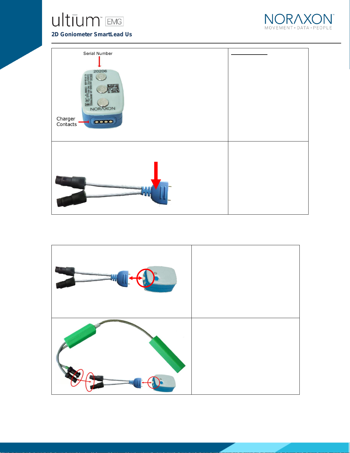
Serial Number –Unique 5-
character serial number
which identifies each EMG
sensor.
2D Goniometer
SmartLead
Serial Number: Unique 5-
character serial number
which identifies each
SmartLead.
5.3 Component Interconnections
Step 1
Connect the 2D Goniometer SmartLead
to the Ultium Designated Ultium Sensor
(See ‘MR3 Configuration’ Section below
for instructions on how to designate a
SmartLead to a specific Ultium Sensor)
Step 2
Connect the 4-pin plugs of the 2D
Goniometer SmartLeads to the X-Y
Goniometer Sensor sockets. The Ultium
SmartLead and the Goniometer sensor
lead with the green tape are the x-axis.
Insert the Ultium SmartLead plug with
the green tape into the Goniometer
sensor socket with green tape. Do the
same for the gray (unmarked) leads. *

2D Goniometer SmartLead User Manual
11
(Rev D January 2020)
*Note: The 2D Goniometer is calibrated to a specific Ultium SmartLead. Therefore, the goniometer
must be continuously utilized with the SmartLead that it came with. It is recommended that the 2D
Goniometer SmartLead stays connected to the Goniometer at all times to avoid confusion. If the 2D
Goniometer SmartLead and its’ paired goniometer get mixed up, contact Noraxon support
(https://www.noraxon.com/support-learn/support-request/) for information about recalibrating the
goniometer to a new sensor.
5.4 Device Communication (Driver) Software Installation
No driver installation is needed. The Ultium Receiver communicates over the USB port.
5.5 Companion Software Installation
The Footswitch SmartLead is compatible with several different software programs. Identify the
companion software that accompanied the equipment (MR3) and follow the appropriate instructions
given next.
5.5.1 MR3 Installation
1. Insert the MR3 feature map into the PC
2. A menu will automatically pop up
3. Click on “Install MR3” and follow the Wizard’s instructions
4. Double click on the icon to start the MR3 software.
5.6 Companion Software Configuration
Before the Footswitch can be used with the Noraxon Ultium system, the companion software must be
configured to recognize the different components that make up the system. Refer to the Ultium
system’s hardware manual for instructions on the software module (MR3 myoMUSCLE) supplied with
the Noraxon system. For specific settings for the Footswitch SmartLead see below:
When assigned to a channel using the serial number, the software should automatically detect the
sensor as a Footswitch SmartLead:
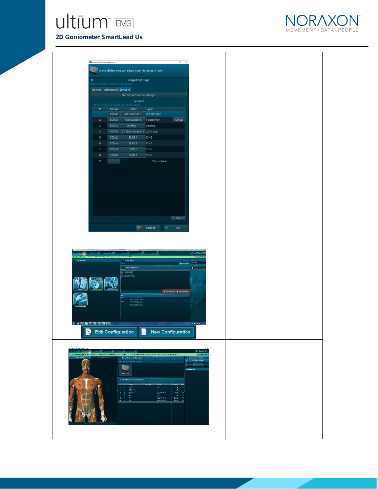
5.6.1 MR3 Configuration
Step 1
Enter the Hardware Setup
screen and setup the Noraxon
EMG system in accordance with
its provided hardware manual.
2D Goniometer SmartLead User Manual
12
(Rev D January 2020)
Step 2
Click ‘Detect Sensors in
Charger’ (All sensors which you
would like to use must be in the
charger) –this will add the
SmartLead(s) to the list of
sensors (only if the unique
SmartLead is connected to their
corresponding sensor). If the
unique SmartLead (ex: 2D
Goniometer) is not connected to
the corresponding sensor during
detection, MR3 will assume you
are using the sensor to collect
EMG data. Click OK.
Step 3
Once back in the Home screen,
choose to create a new or edit
an existing configuration.
It is recommended that you redetect sensors in the
hardware configuration every time the SmartLeads are
Step 4
In the measurement setup
screen, insert the Ultium system
into the Devices section in your
configuration.

2D Goniometer SmartLead User Manual
13
(Rev D January 2020)
removed from the Ultium sensor (redetection is necessary
to revert to the use of the sensor’s EMG functionality). This
will prevent configuration errors leading to the inability to
collect a measurement. If an error message pops up when
starting a measure, and you are using SmartLeads, this is a
good first troubleshooting step (1. Redetect sensors in
hardware set-up; 2. Double check the configuration).
* See Find My Sensor section below
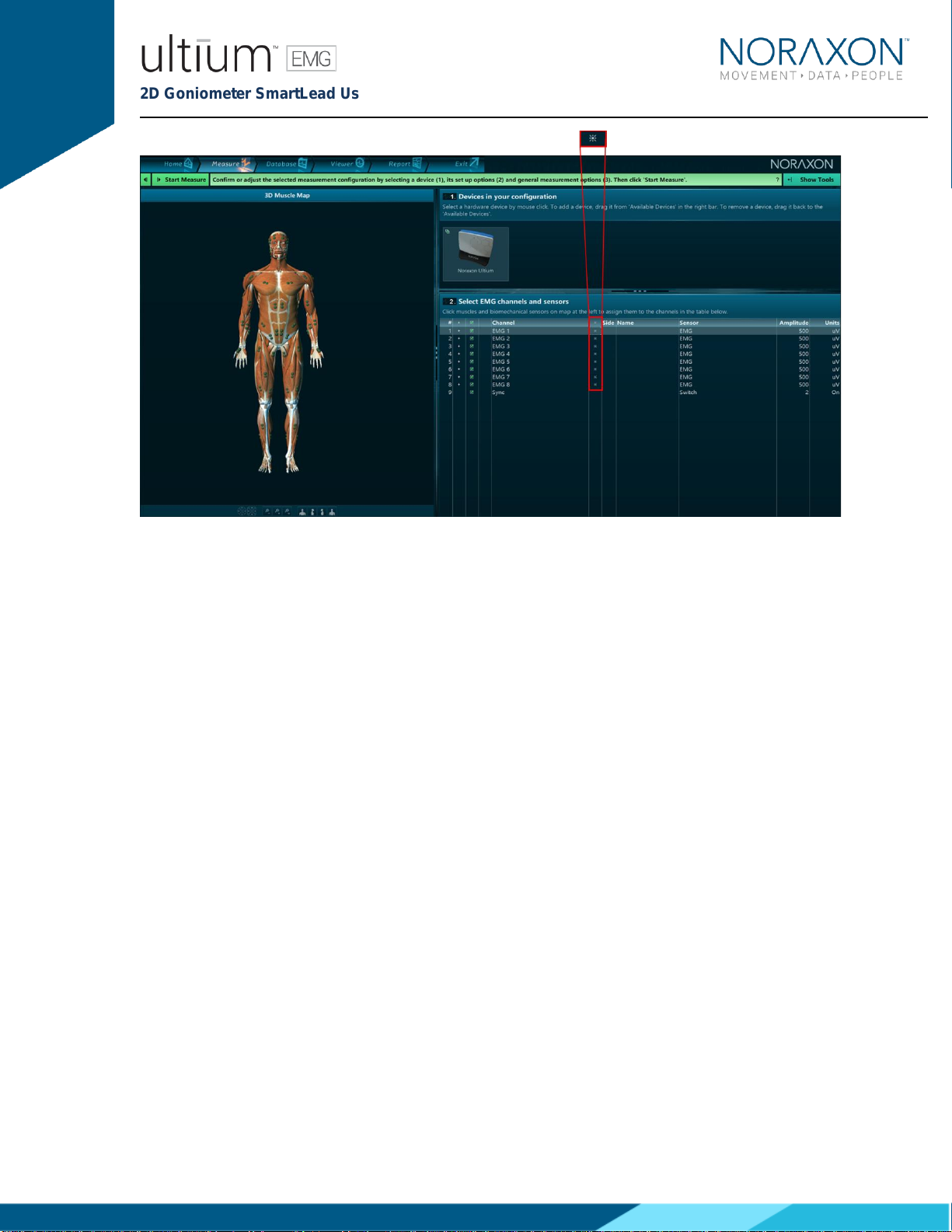
Step 5
Once the Ultium system is
inserted, the muscle map will
appear to the left, and the EMG
channels and sensors will
appear below. The Ultium 2D
Goniometer SmartLead should
automatically appear, as
detected by the Ultium system (if
it does not –refer to step 2).
To select the 2D Goniometer
SmartLead for use in a
recording, check the boxes next
to each goniometer channel (2D
Goniometer 1 X and 2D
Goniometer 1 Y).
Step 5
Continue with the measurement
setup as described in the
Noraxon Ultium system’s
hardware manual.
5.6.2 Find My Sensor Feature
Find my Sensor allows the user to quickly locate a specified Ultium sensor while creating/editing a
MR3 configuration (refer to section 7 for guidance on how to create or edit a configuration). If one of
the stars (refer to the figure below) is clicked, the corresponding sensor will repeatedly blink light
purple in bursts of 3. If the topmost star is clicked, every sensor that is currently in the configuration
will execute the same blinking pattern.
2D Goniometer SmartLead User Manual
14
(Rev D January 2020)

2D Goniometer SmartLead User Manual
15
(Rev D January 2020)
6 Pre-Use Check
6.1 Normal Appearance of Signals
The sensor’s STATUS LED provides a means of communicating its operational state. In the idle
state, the STATUS LED will flash blue at a low, once per second rate. When the sensor is actively
measuring a signal, the STATUS LED will flash recognizably faster (green).
Please review the application diagrams in Appendix B for on the body placement information of the
2D Goniometer sensor for specific joints.
Quick Testing:
To ensure that the 2D Goniometer SmartLead is measuring properly when connected to the Ultium
Sensor, move the two sensors (green endblocks) relative to each other to displace the angle slightly.
You should notice a change in the signal showing angular displacement in MR3.
2D Goniometer SmartLead User Manual
16
(Rev D January 2020)
7 Operating Instructions
7.1 Safety Information Summary
Strictly follow all safety practices given in section 4 of this manual. The most critical ones are
repeated here.
CAUTIONS
•Never use the Noraxon Ultium System on a person with an implanted pacemaker
•Never operate the Noraxon Ultium System within 1 meter of any critical medical device
7.2 Normal Functions with Interface to a PC
When used with the companion software, the 2D Goniometer SmartLead displays and records
signals in degrees.
Consult the user manual for the companion software for descriptions of the setup, playback and
analysis of the data acquired by the Ultium system.
7.3 Exceptional Functions/Situations (error messages)
Please see the appropriate Noraxon system’s hardware manual for possible error messages.
7.4 Shutdown after Use
At the end of the day:
•Place all EMG sensors inside the sensor docking station(s).
•Press the Sensor Power button on the Receiver to power all sensors off.
7.5 Storage and Protecting Between Usages
For extended storage or when travelling:
•Place all sensors into the sensor docking station and power them off by pressing the
Receiver power button. When the sensors are shutdown they will stop blinking completely.
•The sensors are reactivated by pressing the Receiver power button.
7.6 Goniometer SmartLead and Sensor Care
When using goniometers, care should be taken so the sensors are only handled and manipulated as
instructed. Mishandling may result in inaccurate data, reduced life or failure.
When using goniometers, the minimum bend radius (no less than 18mm) must be
observed at all times, particularly when attaching and removing the sensors from the
subject. Failure to do this will result in reduced life.
Under no circumstances should the sensor be removed from the subject by pulling on
the measuring element and protective spring. The endblocks must be removed
!
!

2D Goniometer SmartLead User Manual
17
(Rev D January 2020)
individually and carefully making sure that the minimum permissible bend radius is
observed, particularly where the measuring element enters the endblocks.
When cleaning or disinfecting goniometers, remove them from the Ultium SmartLead
to prevent liquid from leaking into the Ultium SmartLead and Sensor.
When using SG series sensors, care should be taken during mounting so that the
measuring element always forms a “simple” bend shape. If an “oxbow” shape occurs
in the element, this will reduce accuracy.
This results when the sensor is
compressed too much. This can damage
the sensor. Do NOT mount the sensor in
this way.
When using F series goniometers, the sensor should not be bent more than 20in
the y-y plane, otherwise reduced life or failure will result.
Single Axis Goniometer F35
POSITION 1
L 1
!
!
!

2D Goniometer SmartLead User Manual
18
(Rev D January 2020)
7.7 Goniometer Maintenance
The sensors contain no user serviceable components. In the event of malfunction, the sensor should
be returned to the supplier, accompanied by a description of what has been observed and what
instrumentation was in use.
No periodic maintenance is required to ensure the correct functioning of the sensors.
2D Goniometer SmartLead User Manual
19
(Rev D January 2020)
8 Cleaning
8.1 Safety Precautions When Cleaning
WARNING
Only use a damp cloth with mild soap and water or isopropyl alcohol to clean the
bottom of the Ultium Sensors.
Do not immerse Ultium Sensors in any water or liquid.
8.2 Cleaning by Users
It is advisable to clean the 2D Goniometer SmartLead on a regular basis. The 2D Goniometer
SmartLead can be cleaned with a cloth slightly dampened with a solution of mild soap and water or
disinfectant solution(i.e. isopropyl alcohol swabs or household disinfectant wipes).
The 2D Goniometer SmartLead is not warranted against exposure to any of the conventional forms of
sterilization(autoclave, heating, etc.). Users wishing to utilize this equipment in a sterile environment,
such as an operating theater, should consult Noraxon for other options.
When cleaning or disinfecting, the sensors must be disconnected from all
instrumentation.
No solvents, acidic or strong alkaline materials should be used to clean the
sensors or damage will result.
To clean the 2D Goniometer, wipe the sensors (green endblocks) with a damp cloth or a cloth
moistened with soapy water.
To disinfect the 2D Goniometer, wipe the sensors (green endblocks) using a cloth moistened with an
allowable disinfectant.
!
!
2D Goniometer SmartLead User Manual
20
(Rev D January 2020)
9 Maintenance
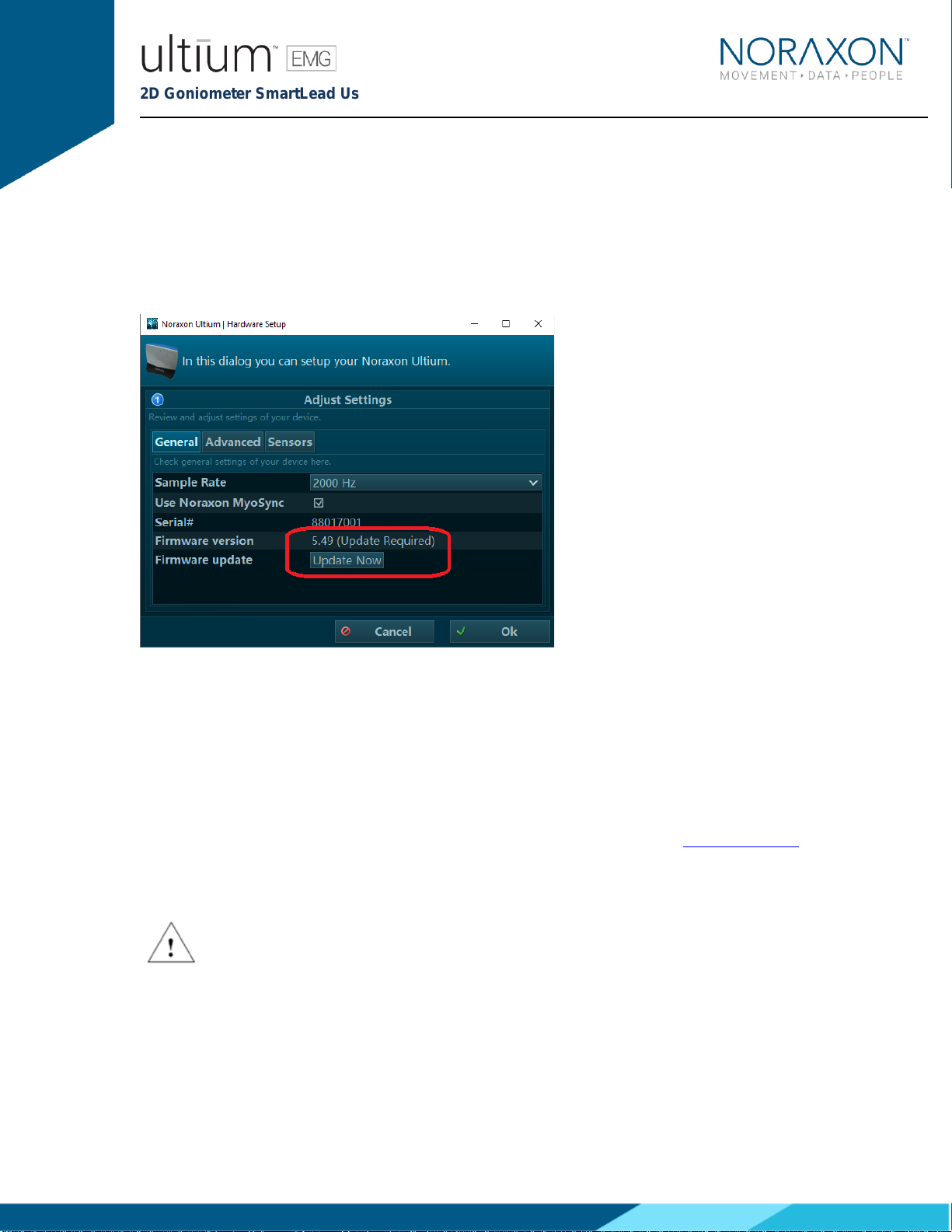
9.1 Device Software (firmware) updates
The internal program (firmware) inside the various Ultium devices can be updated via MR3. The user
will be notified within the Ultium System hardware setup if an update is required. Ensure that all
sensors are placed in the Ultium charging doc and that the charging doc is connected to the Ultium
receiver prior to initiating the firmware update. If you start the update prior to completing this step, you
may need to update again (firmware update button will still be present in hardware setup).
9.2 Maintenance by Qualified Individuals
The following activities should only be undertaken by PC support (IT) personnel, equipment
technicians or those with suitable training.
9.3 Companion Software Updates
•Perform a backup of the data folders to a separate drive as a precaution.
•Click on the Patch/Update link provided in the email or as given on the Noraxon website.
•Download the Patch/Update file.
•To install the Patch/Update, click “Run” on the dialog box. No password is required.
9.4 Attention
All EMG sensors should be fully charged before a firmware update is performed.
This manual suits for next models
2
Table of contents
Other Noraxon Laboratory Equipment manuals


