CYTENA x.sight Mounting instructions

x.sight
software manual
cytena GmbH
Supporting
software versions
1.0.7 or higher

x.sight - software manual
2 | P a g e
8th edition English 08/2019
Documentation © 2018-2019 cytena GmbH, Freiburg, Germany
All rights reserved. Without the written consent of the publisher this manual or any part of it may not be in any
form reproduced or distributed using electronic, mechanical or chemical processes. It is possible that the
present manual still contains typographical or printing errors. The information in this manual however, is
regularly reviewed and corrections are made in the next output version. For technical or typographical errors,
we provide no liability for the nature and consequences thereof.
All trademarks and copyrights are acknowledged.
Printed in Germany.
Changes in terms of technical progress are subject to change without notice.

x.sight - software manual
3 | P a g e
Content
1About this manual .......................................................................................................... 5
2Technical information..................................................................................................... 6
2.1 General information: ........................................................................................................ 6
2.2 Embedded PC information: .............................................................................................. 6
2.3 Data properties:................................................................................................................6
2.4 Third party hardware........................................................................................................7
2.5 Drivers and additional software .......................................................................................7
3Software overview ......................................................................................................... 8
3.1 General handling .............................................................................................................. 8
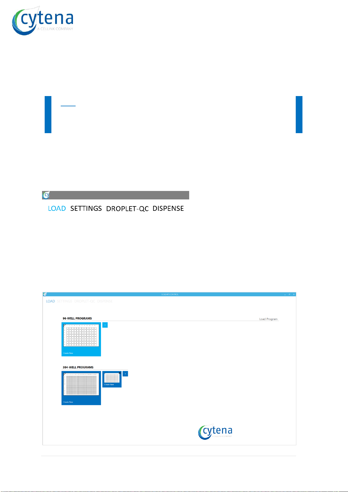
3.2 Start screen (LOAD) .......................................................................................................... 8
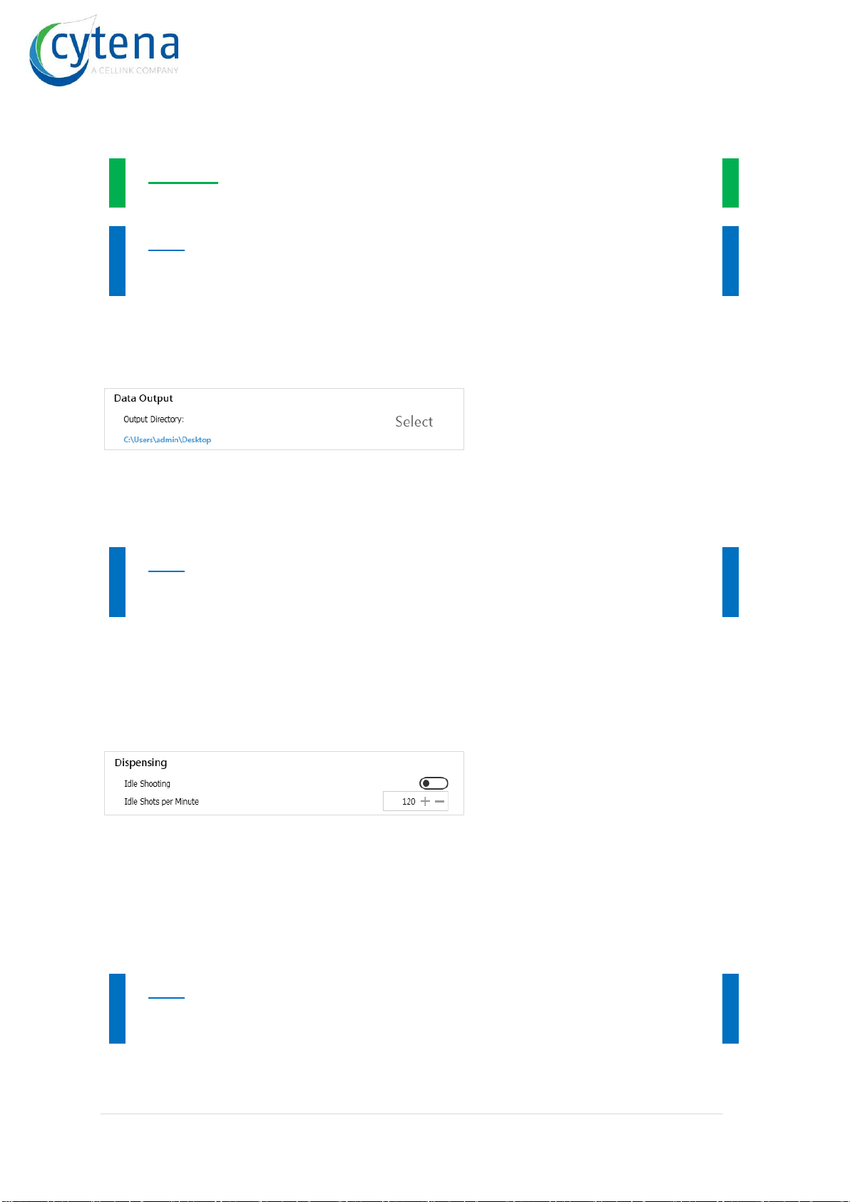
3.3 Settings (SETTINGS) ..........................................................................................................9
3.4 Droplet quality control (DROPLET-QC) ........................................................................... 13
3.5 Main screen (DISPENSE) .................................................................................................15
3.6 Cell Camera & Region of Interest (ROI) ..........................................................................18
3.7 Results ............................................................................................................................21
3.8 Live log window ..............................................................................................................22
4f.sight special ............................................................................................................... 24
4.1 Cell camera modes ......................................................................................................... 24
4.2 Camera alignment mode ................................................................................................25
4.3 Collect sample modes.....................................................................................................27
5Software use ................................................................................................................ 28
5.1 Starting sequence........................................................................................................... 28
5.2 Chose a well plate or load a program............................................................................. 28
5.3 Set up your experiment..................................................................................................28
5.4 Configuring your well plate ............................................................................................28
5.5 Loading cartridge and well plate ....................................................................................31
5.6 Set Region of Interest (ROI)............................................................................................32
5.7 Performing Droplet-QC...................................................................................................32
5.8 Performing the experiment............................................................................................34
5.9 Data ................................................................................................................................ 34
6Configuration & OS....................................................................................................... 35
6.1 Use of antivirus and security software........................................................................... 35

x.sight - software manual
4 | P a g e
6.2 Domain & domain users................................................................................................. 35
6.3 Connection to local network.......................................................................................... 35
6.4 Connection of additional drives..................................................................................... 35

x.sight - software manual
5 | P a g e
1 About this manual
Before putting the x.sight device into operation, please read the instructions given within
this manual carefully and keep this document safe.
This manual contains information about the software and its usability. The manual is
containing hints and examples helping to guide the user and show him/her where to pay
special attention. These are color coded like shown below:
Example: this is an example text.
Hint: this is a note text.
Disclaimer of warranty
The x.sight device is designed for research and may not be used for diagnostic
applications.
This is the software manual of the x.sight. Please note that no warranty of any kind will be
given. The cytena GmbH assumes no liability for improper handling.
The x.sight device must only be operated by trained personnel. The cytena GmbH
assumes no liability for damages incurred due to improper handling of the device and the
device components (cartridge, etc.).

x.sight - software manual
6 | P a g e
2 Technical information
2.1 General information:
Platform
Microsoft Windows
Framework
.NET 4.6.x or higher
DLLs
64-bit
Supported OS
Windows 7 (x64)
Windows 10 (x64)
Automation interface
API and DLL available
Installation
msi self-installer
Space requirements for installation
400 MB hard drive capacity on C:\
Updates
Download (as installer)
Internet connection
Not required
2.2 Embedded PC information:
OS
Win7 (x64) Professional (until 2019)
Win10 (x64) Professional (from 2020)
CPU
Intel Core i7 6700 @ 3.4 GHz
RAM
8 GB DDR-4
Hard drive
240 GB SSD, SATA M2
Partition C:\ (OS)
100 GB
Partition D:\ (data)
130 GB
External interfaces
1x DVI
1x Displayport (DP++)
2x GigE LAN
4x USB-3.0
2.3 Data properties:
Program log data format
XML
Image data format
JPEG
Image resolution
1.3 Mpixels (1280x1024)
Image color format
8-bit greyscale
32-bit RGB (f.sight)
Images per single-cell
5
15 (f.sight)
Data volume per single-cell
1.2 MB
5.0 MB (f.sight)
Data volume per 96-well plate
115 MB
480 MB (f.sight)

x.sight - software manual
7 | P a g e
Data volume per 384-well plate
460 MB
1.9 GB (f.sight)
2.4 Third party hardware
The x.sight will be delivered including keyboard, computer mouse and monitor. Customers
may exchange this hardware by internal peripheral standards. The following conditions
shall be met:
Min. monitor resolution
1920x1080 (HD)
Compatible monitor interfaces
DVI
HDMI
Displayport (DP++)
Compatible keyboard interface
USB-2
Compatible mouse interface
USB-2
2.5 Drivers and additional software
MS .NET framework
4.6 or higher
IDS USB driver
4.90 or higher
TMCL motor driver
1.1 or higher
WHQL MSP32 driver
2.24 or higher
AIMB Chipset driver
USB Chipset driver
BIOS version

x.sight - software manual
8 | P a g e
3 Software overview
The x.sight will come up with a single application desktop software preinstalled and ready
to be used on the embedded PC. This chapter will introduce the User Interface (UI) and
the handling of software together with hardware required user actions as well as explain
the full software functionality in detail.
Hint: Some of the software functions and buttons described in this manual may
not be available on your device. This depends on the configuration and device
type you have. For any question, please contact technical support.
3.1 General handling
The software contains four main tabs: LOAD, SETTINGS, DROPLET-QC and DISPENSE.
In order to complete the setup process and print a plate, you have to work through these
four tabs from left to right.
The active tab is highlighted in blue, like in the above example the LOAD tab. The non-
active tabs are grey. The following sections explain the single tabs and the options and
buttons on their respective UI pages.
3.2 Start screen (LOAD)
Start the software by using the link on the desktop. After the boot sequence is completed,
the LOAD / start screen appears.

x.sight - software manual
9 | P a g e
The start screen shows (by default) two large tiles, one for 96-well plates and one for 384-
well plates. A click on these tiles opens the main screen with an empty plate in the
respective format.
The small [+] tiles next to the large tiles allows for adding existing preconfigured programs
as tiles to the start screen. A click on [+] opens a dialog. Chose an existing program and
add it as tile to the start screen. Once added, it will appear permanently on the start screen
when the software is loaded. An existing tile can be deleted using the [x] button inside it.
Once deleted it is permanently deleted and has to be re-added if required.
The [Load Program] button in the top right corner can be used to directly load an existing
program. This will not add a tile to the start screen but load the program directly into the
main window.
3.3 Settings (SETTINGS)
Enter the [SETTINGS] tab of the software to get access to the main options and
parameters. You can set default parameters as well as activate or deactivate functions.
The first section called [Agitation] deals with the settings for the automatic mixing unit
(called agitation) that ensures homogeneous distribution of cells throughout time in the
cartridge reservoir.
The toggle switch [Status] enables and disables the agitation. A white switch represents
“off” and a colored switch represents “on” state. The field [Repetitions per Minute] defines

x.sight - software manual
10 | P a g e
the number of mixing cycles per minute performed by the system. The field [Volume]
defines the aspirated and dispensed volume per cycle in microliters.
Example: Typical values would be Repetitions = 15, Volume = 10 µl
Hint: Make sure you have set reasonable settings, so that the agitation is truly
mixing the cells inside the reservoir. Too low parameters
The section [Data Output] defines the output directory for the experiment data being
creating in every experiment run. Click on the [Select] button to open the dialog. Select
any path and folder from your system or network.
The selected path is then shown below. It is set permanently until being changed, also
when software is restarted. In this selected folder, each experiment is separately saved in
its own subfolder.
Hint: Chose a reasonable storage path. Drive D:\ is recommended. Make sure
that the location has sufficient free space for saving data.
The section [Dispensing] represents the possibility to enable an automatic idle dispensing
mode (called idle shooting). To enable it, turn on the [Idle Shooting] switch. A white switch
represents “off” and a colored switch represents “on” state. The [Idle Shots per Minute]
function let you control how fast the idle dispensing is performed.
When activated, [Idle Shooting] mode generates the set number of droplets per minute.
All droplets are being sucked away by the vacuum shutter system. This ensures that no
target is contaminated, but the cartridge is kept usable as long as no experiment is
performed. The mode will be deactivated automatically when DQC is performed or a
printing experiment is started. It will automatically reactivate after DQC or the experiment
has been completed.
Hint: Idle Shooting is recommended to use when there are longer (> 5 min)
holding timesbetween experiments andyou want to continue usingthecartridge.

x.sight - software manual
11 | P a g e
Some cell media tend to evaporate quickly on the open nozzle. This leads to
crystallization of the nozzle. The nozzle then is clogged after some minutes. The
continuous, slow generation of droplets prevents this.
The section [Tracking Algorithm] contains the two main properties for the cell detection
algorithm.
The [Detection Radius] defines the ROI radius in micrometers. Default value is 125. It can
be adapted for specific needs (e.g. very low or high viscous media).
The [Detection Threshold] defines the threshold between foreground (= cells or particles)
and background (= chip) of the image. The threshold required to distinguish foreground
objects from the background in image processing. The lower the contrast of objects
against the background, the lower the threshold has to be set. Default value is 25. The
value is automatically taken over and is set permanently until changed, even when
software is restarted.
Hint: The cell detection is sensitive against this value. Too low values will
generate noise and ghost objects that disturb detection. Too high values will
prevent detection of any object, even those with high contrast. Find a suitable
value for your application. A good range is 20 - 40.
The section [Deionisator] allows you to enable automatic plate deionization prior to
printing. To enable it, turn on the [Perform Deionisation] switch. A white switch represents
“off” and a colored switch represents “on” state.
When being activated, each plate is deionized before the actual printing experiment is
performed. The deionization process takes only seconds.
Hint: When using foil based plates (e.g. PCR plates) deionization is
recommended to activate. Droplets may carry electric charge. When the plate is
ionized as well, droplets may not land in the wells precisely.
When using “Offset Compensation” mode, deionization must be activated to
ensure straight droplet flight into the plate.

x.sight - software manual
12 | P a g e
The section [Offset Compensation] offers a high precision printing mode. To enable this
mode, turn on the [Use Offset Correction] switch. A white switch represents “off” and a
colored switch represents “on” state.
The [Offset Compensation] measures the droplets flight trajectory in space and corrects
the axis system with an offset to ensure that the droplet is landing centered in the well.
The automatic correction requires the distance the droplets travels until reaching the
bottom of the well. The input field [MTP Well Depth] let you enter this distance in
millimeters.
When being activated, this mode performs the compensation prior to each experimentrun.
Compensation can take up to 3 minutes. It is fully automatic.
Hint: The [Offset Compensation] mode is recommended when using targets
that require a high precision in droplet positioning. For example 384-well plates
with conical wells for PCR or sequencing applications.
It can also be useful when targeting special plates or special applications where
the position of the single-cell on the target is crucial.
Using this mode may significantly increase the total process time per plate.
The section [Automation Settings] contains the relevant settings for running the x.sight in
an automation environment using the cytena API.
To connect the software with the client, the opposite server has to be started as well. Next
to [Automation Server] use the [Start] button to connect server and client. [Server Port
Number] refers to the TPC/IP Port used for connection. [Dispensing Event Warning
Threshold] and [Dispensing Event Error Threshold] refer to the warning and error events
being sentto the automation controller. A counterdetects the number of dispenses without
a single-cell event. If the respective thresholds are exceeded, the warning or error is
transmitted.
Hint: For further information please refer to the API handbook.

x.sight - software manual
13 | P a g e
3.4 Droplet quality control (DROPLET-QC)
First step in experimental setup is verification of dispensing performance. Meaning each
new cartridge needs to be calibrated to its loaded sample with regard to droplet generation.
A reproducible and robust droplet generation is required prior to experiment. Therefore the
droplet quality control (DQC) is built in.
The respective window in the software is called [DROPLET-QC] and can be opened from
the main menu.
DQC working principle is stroboscopic droplet imaging. Stroboscopic imaging allows for
observing the generated droplets live and in flight. The window shows a separate camera
view.
Under [Droplet Position] you find three sliders that help to center the droplet in the cameras
field of view and bring it in focus.
•[Vertical/Delay] time delay between drop generation and photo acquisition
•[Horizontal] horizontal position of the droplet, controlled by X-axis
•[Focus] focal position of the droplet, controlled by Y-axis
The sliders under [Stroke Settings] define the actuation of the piezo. Here, stroke means
the swing of the piezo that performs the mechanical deformation of the chip membrane.
Physically the piezo extents, driven a plunger that deflects the membrane. The piezo
extension is defined by two parameters:
•[Length] the geometric length the piezo is extended
•[Speed] the velocity with which the extension is taking place
Both [Length] and [Speed] define the properties of the generated droplet. Length is mainly
influencing droplet volume. Speed is mainly influencing the droplet velocity.

x.sight - software manual
14 | P a g e
The check box under [Vacuum Settings] allows for switching on and off the vacuum shutter
that takes off unwanted droplets. To see a droplet in the DQC camera window, the vacuum
has to off, meaning the box has to be unchecked. The vacuum system is equipped with a
pressure sensor. The actual pressure can be seen (as digital value) next to the checkbox.
Hint: The vacuum checkbox allows for checking, if the vacuum shutter system
works reliable. It is switched off by default when entering the DQC mode. This is
mandatory to see the droplet in the camera window.
When checking the vacuum checkbox, the shutter will be switched on and the
droplet should disappear in the camera window. This is the proof, that the shutter
system is working for the given piezo parameters and the used cartridge and
sample.
Show the droplet not disappear, the system is not working. You should not
continue printing in this case!
You can start and stop the DQC any time using the [Start] / [Stop] button. When entering
the DQC mode the system is switched on automatically. When leaving the DQC mode it
is stopped automatically.
Hint: When entering DQC mode, the axis system is centering the cartridge in
front of the DQC camera at a default position with a default photo delay. Ideally
this position enables you to directly see the droplet in the camera window.
In case you don’t see a droplet, use the sliders under [Droplet Position] to search
for the droplet manually.
The button [Capture DQC Images] allows for saving a sequence of images from the DQC
camera.

x.sight - software manual
15 | P a g e
3.5 Main screen (DISPENSE)
The main (or print) screen is the central part of the UI. It contains an interactive, digital well
plate that can be freely configured. On the right side, you can find the cell camera live
window and the parameter plot.
In the [Name] field you can insert any name for your experiment.
In the [Description] field you can enter a full text description as well as any additional
information about your sample, plate type, etc.
In the [Plate ID] field you can enter your plate barcode or plate name. Here you can use
the included barcode scanner to read the barcode from your plate into the field.
The [SAVE AS] button let you save the current configuration at any time. A previously
saved configuration can be reloaded from the start screen. Click on the [LOAD] menu
button to return to the start screen.
Hint: If you want to save your experiment, you need to set a name at least.
Description and plate ID can be left void. Use the [SAVE AS] button to save the
experiment.
Please note that only the actual experiment configuration is saved. When you
perform changes on the configuration, you have to save again to take over the
changes.

x.sight - software manual
16 | P a g e
The interactive well plate [MTP Configuration] allows for
•selection of single wells by left mouse click
•selection of multiple wells by CTRL + left mouse click
•selection of multiple wells by a rubberband (drag, hold, release left mouse)
•selection of all wells by left mouse click into the grey top left corner of the plate
When at least one well is selected, below the platethe configuration for the selected well(s)
appears. This includes:
•[Action] defines the action to be performed in the well(s)
•[No. of …] defines the number of events to be performed
•[Size] defines the range of cell diameter for cells to be sorted
•[Roundness] defines the range of cell roundness for cells to be sorted
•[FL intensity] defines the range of fluorescence intensity
As [Action] you can choose from
•[Print cell] prints a single droplet that contains one cell
•[Print FL cell] prints a single droplet that contains one fluorescent cell
1
•[Print NTC] prints a void single droplet (no cell inside)
•[Print every droplet] prints a single droplet independent from its content
Hint: Besides printing single-cells, the software is also capable of delivering
empty droplets as a negative template control (NTC) for applications that use
assays after cell sorting.
Also the software can print droplets independent from their content (void, single-
cell or multiple cells). This function enables quick delivery of a certain sample
volume into specific wells.
The [No. of …] input field allows for defining the repetitions of the chosen [Action] to be
performed in the specific well(s). It changes depending on the action.
Example: the following example illustrate how Action and No. of are related to
each other and how you can generate different configurations.
[Action] = [Print cell] and [No. of cells] = 10
→
prints 10 cells into the well
[Action] = [Print every droplet] and [No. of droplets] = 100
→
prints 100 droplets into the well, no matter what they contain
[Action] = [Print NTC] and [No. of NTC] = 1
→
prints 1 void droplet into the well
1
Available for f.sight only.

x.sight - software manual
17 | P a g e
The fields for [Size] and [Roundness] are only available when [Print Cell] as [Action] is
chosen. The following screens show the different appearance and color coding of actions.
[Dispense cell]
Color code: red
Sliders for size and roundness
visible below plate
Different configurations on
different wells appear as different
shades of color code
[Dispense NTC]
Color code: grey
Sliders invisible
Different configurations on
different wells appear as different
shades of color code
[Dispense every droplet]
Color code: blue
Sliders invisible
Different configurations on
different wells appear as different
shades of color code

x.sight - software manual
18 | P a g e
[Dispense fluorescent cell] *
Color code: green
Sliders: size and roundness plus
FL intensity [a.u.]
Different configurations on
different wells appear as different
shades of color code
* Available in f.sight only!
The [PLAY] button let you start the actual printing process. As soon as this is started, the
button turns into a [STOP] button. The process can be aborted any time by clicking this
button. Once aborted, it cannot be continued. You have to restart the experiment.
During operation, the well will change its appearance according to its state. There are
basically three different states:
not processed
The well is colored with respect to the chosen Action
(e.g. green for Print fluorescent cell)
in process
When the system operates over a well, this is indicated
by circulating dots (standard waiting pictogram)
completed
Once the action in this well is successfully completed,
a tick mark is shown
3.6 Cell Camera & Region of Interest (ROI)
The cell detection camera (Cell Camera) shows the live stream of the dispenser cartridge,
respectively the nozzle area. The camera is located in the top right corner of the software
main window. The c.sight and b.sight camera is standard bright field (left image) while the
f.sight features an additional fluorescence camera (right image).

x.sight - software manual
19 | P a g e
The live video stream displays the ROI (so called “region of interest”) as three circles
around the nozzle. The green circle of the ROI defines the fluid volume that is expelled
from the chip nozzle when a droplet is generated. The two blue circles define three areas
(A-C) like shown the schematic below:
Only when a single-cell is detected inside region A(inner blue circle) and no other object
is inside region B(between the two blue circles), the single-cell is printed to the substrate.
The correct position of the ROI is crucial to achieve good printing results. The following
reference shows you how to set the ROI. The ROI is vertically centered in the nozzle
(vertical yellow dashed line, left figure). Horizontally, the inner blue circle should touch the
nozzle orifice (red arrows + red dashed line, right figure).

x.sight - software manual
20 | P a g e
To perform an automatic detection of the ROI, press the [Autodetect ROI] button below
the video window. Visually confirm the correct detection according to the reference above.
In case the ROI is not centered over the nozzle asshown below, simply click into the video
field to set the ROI manually. Left click into the video window. Your mouse pointer defines
the center of the circles. Aim as follows:
You can also use the zoom function to enlarge the view. To do so, press the [Roi view]
button below the Cell Camera window. The camera will now show the area around the
ROI in higher magnification. Click in the window to do corrections if required. To close
the enlarged view, press [Roi view] again.
Hint: Whenever you mount a new cartridge to the x.sight, you have to reset the
ROI either automatically or manually. The system does not recognize when a
cartridge is changed.
When pressing the [PLAY] button without having set a ROI initially, the system
will show a respective message and perform the [Autodetect ROI] function
automatically before starting the printing process.
Table of contents
Popular Laboratory Equipment manuals by other brands

Hydro systems
Hydro systems HydroChem 912 quick start guide

Qiagen
Qiagen TissueLyser II user manual

Bruker
Bruker AVANCE NEO user guide

Accurion
Accurion i4 Series operating instructions

Judo
Judo JUV 20 G Installation and operating instructions

Fisher Scientific
Fisher Scientific Fisherbrand Isotemp RT AVCD HPS Advanced Operation manual