ROBOT . HEAD to TOE
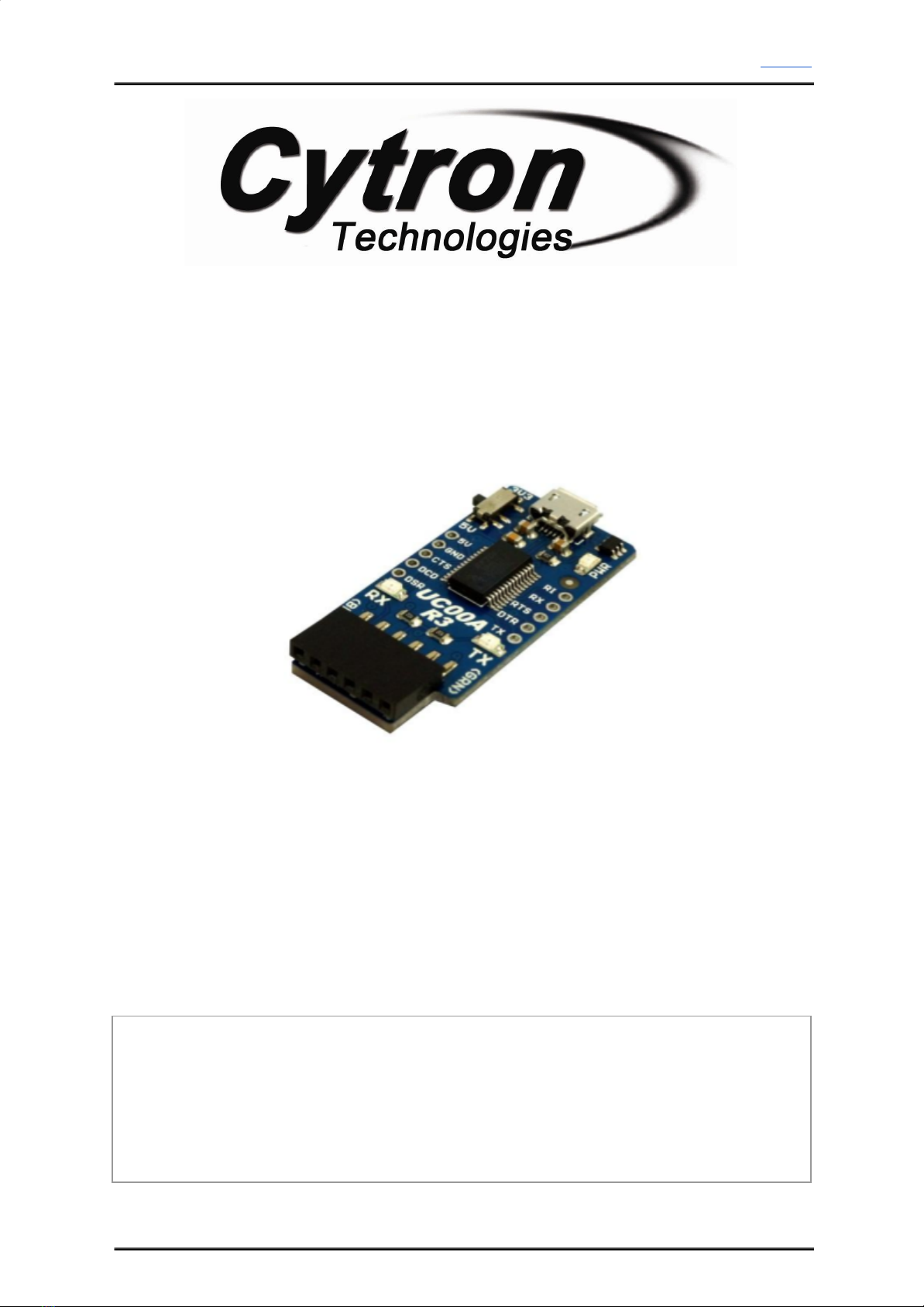
Product User’s Manual – UC00A
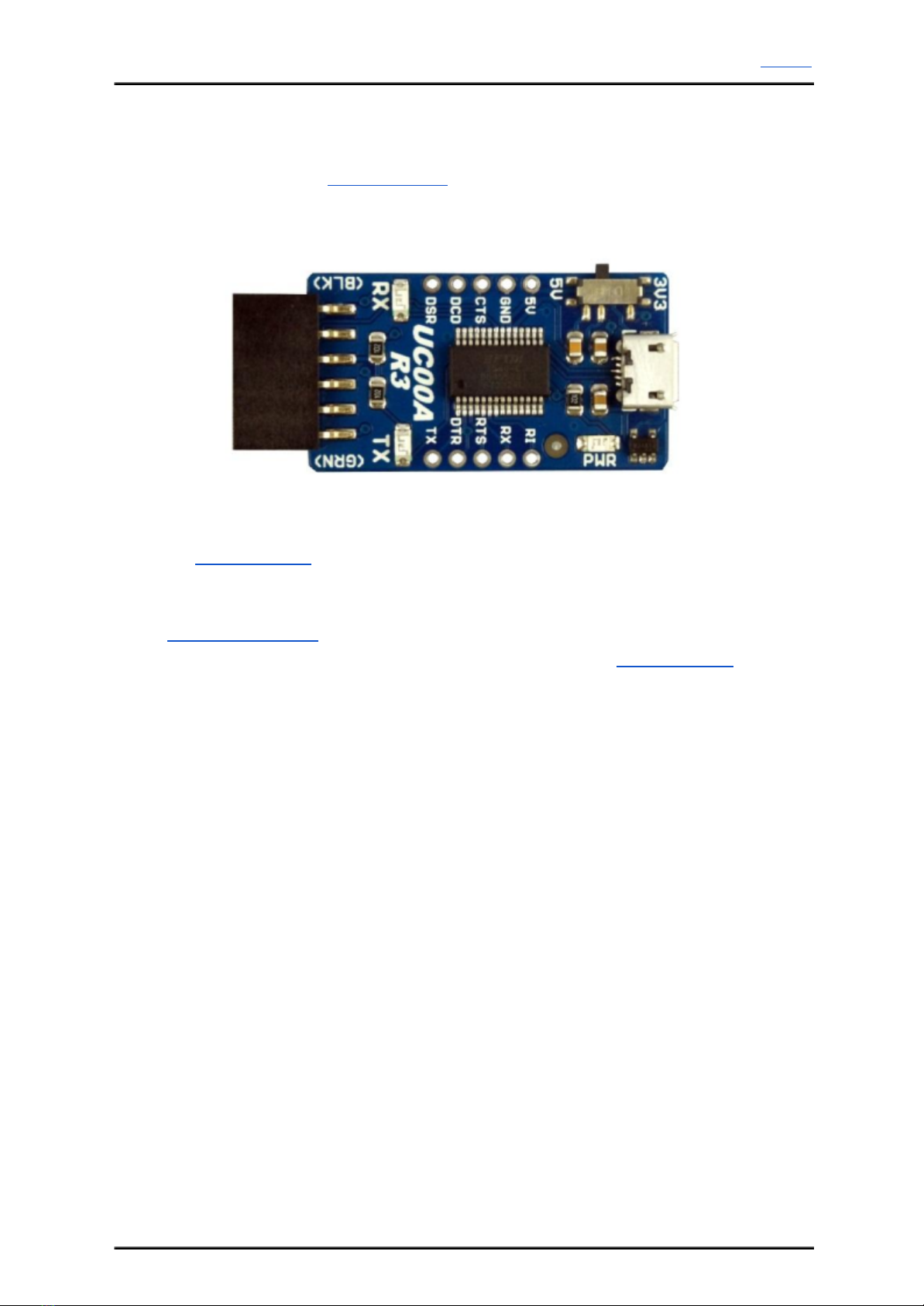
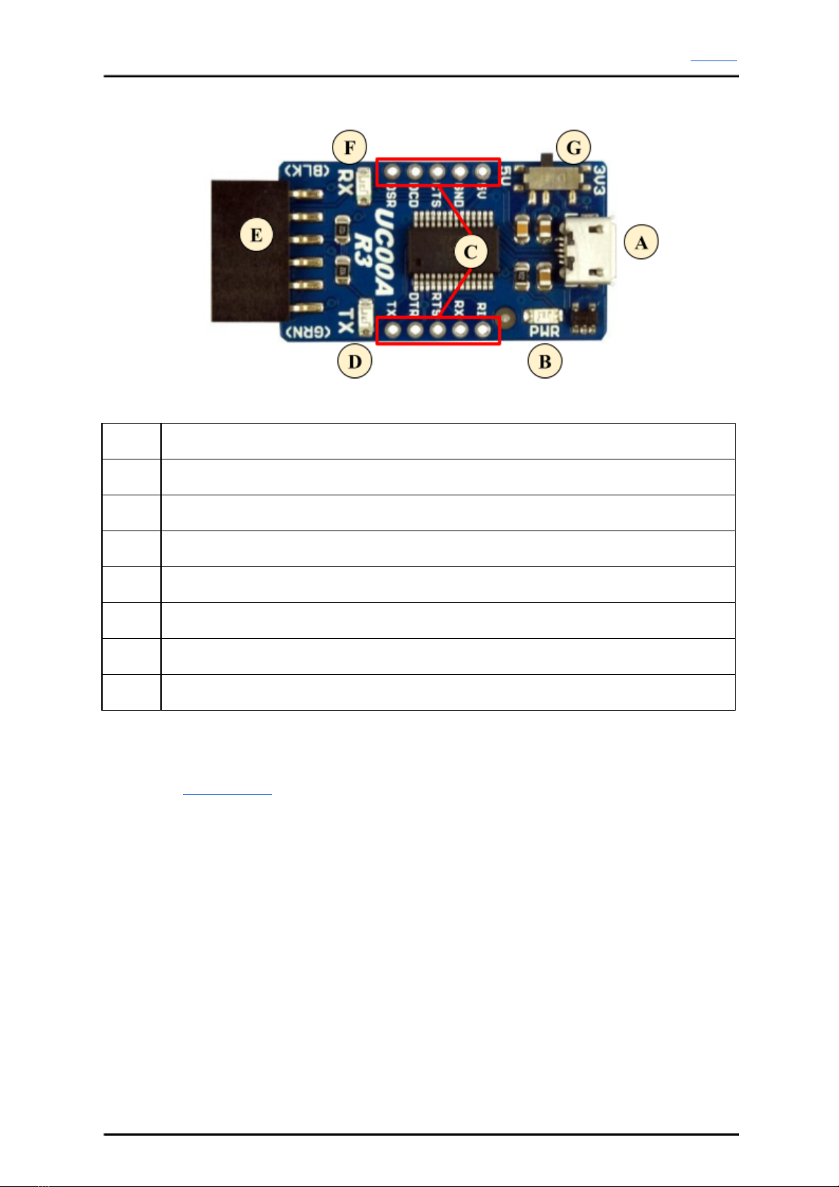
Standard 6-way header socket
Header socket at “E” is breakout of pins which are commonly used for loading program to
Arduino PROMini, BBFuino, Fio and others.
RX LED
LED at “F” is FTDI’s RX indicator LED. This LED is to indicates the receive activity from
FTDI chip, or receive activity at computer virtual COM port. It will only work if UC00A is
connected to PC or laptop.
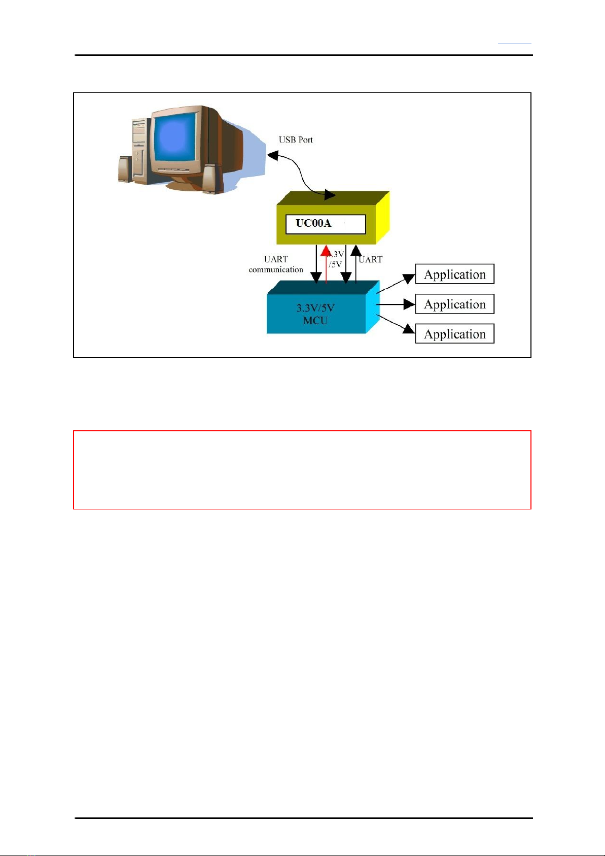
Vsel, VCC and Logic selectable Switch
Vsel at “G” is a slide switch to determine voltage option for TTL level of UART interface
pins, and also the voltage at VCC pin at header socket at “E”. User may choose either 3.3V or
5V. If 5V is chosen, all the interface pins include TX, RX, DTR, CTS, RTS, DSR will be in
5V TTL logic and the VCC at “E” will be 5V too. On the other hand, if Vsel at “G” is 3V3,
all interface pins will be in 3.3V TTL logic and VCC at “E” will be 3.3V too.
Created by Cytron Technologies Sdn. Bhd. – All Rights Reserved 8