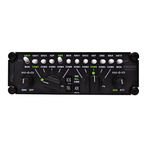
PS Engineering PAC45T User guide

9800 Martel Road
Lenoir City, TN 37772
www.ps-engineering.com
PAC45T
Special Mission Audio Controller System
with IntelliVox®
Document P/N 200-045-5100
Revision 2 January 2019
Audio Control System with Intercom
System Installation and Operation Manual
FAA - TSO C139a
Patented under one or more of the following;
No. 4,941,187; 5,903,227; 6,160,496 and 6,493,450, 7,391,877
PS Engineering, Inc. 2019 ©
Copyright Notice
Any reproduction or retransmittal of this publication, or any portion thereof, without the expressed written permission of PS En-
gineering, Inc. is strictly prohibited. For further information, contact the Publications Manager at PS Engineering, Inc., 9800
In certified aircraft, warranty is not valid unless this product is installed by an
Authorized PS Engineering dealer.

Table of Contents
Section I –GENERAL INFORMATION................................................................1-1
1.1 INTRODUCTION.............................................................................................................................................1-1
1.1.1 LIMITATIONS.....................................................................................................................1-1
1.2 SCOPE................................................................................................................................................................1-1
1.3 EQUIPMENT DESCRIPTION........................................................................................................................1-1
1.4APPROVAL BASIS FAA TSO.........................................................................................................................1-1
1.1.2 LIMITATIONS.....................................................................................................................1-1
1.5 SPECIFICATIONS...........................................................................................................................................1-2
1.6 EQUIPMENT SUPPLIED................................................................................................................................1-2
1.8 CONFIGURATION .................................................................................................................................................1-5
1.9 LICENSE REQUIREMENTS..........................................................................................................................1-5
Section II - INSTALLATION 2-1
2.1 GENERAL INFORMATION...........................................................................................................................2-1
2.1.1 SCOPE..............................................................................................................................2-1
2.1.2 CERTIFICATION REQUIREMENTS ......................................................................................2-1
2.2 UNPACKING AND PRELIMINARY INSPECTION......................................................................................................2-1
2.3 EQUIPMENT INSTALLATION PROCEDURES ..........................................................................................................2-1
2.3.1 COOLING REQUIREMENTS ................................................................................................2-1
2.3.2 MOUNTING REQUIREMENTS.............................................................................................2-1
2.3.3 AUDIO CONTROLLER CONNECTOR ASSEMBLY.................................................................2-2
2.4 CABLE HARNESS WIRING....................................................................................................................................2-3
2.4.1 ELECTRICAL NOISE...........................................................................................................2-3
2.4.2 POWER ..............................................................................................................................2-3
2.4.3 AUDIO CONTROLLER INTERFACE......................................................................................2-4
2.4.4 BACKLIGHTING.................................................................................................................2-4
2.4.5 UNSWITCHED INPUTS........................................................................................................2-4
2.4.6 COCKPIT VOICE RECORDER..............................................................................................2-4
2.4.7 AUDIO ALERTS .................................................................................................................2-5
2.5 USER ADJUSTMENTS............................................................................................................................................2-5
2.5.1 UNSWITCHED AUDIO LEVEL ............................................................................................2-5
2.5.2 ADJUSTMENTS ..................................................................................................................2-5
2.5.3 LOGIC SWITCH OPTIONS...................................................................................................2-6
2.6 PAC45T PIN ASSIGNMENTS ................................................................................................................................2-9
2.7 WIRING CHECKOUT ..........................................................................................................................................2-10
2.8 OPERATIONAL CHECKOUT................................................................................................................................2-11
2.8.1 REQUIRED TEST EQUIPMENT..........................................................................................2-11
2.8.2 AUDIO CONTROLLER TEST..............................................................................................2-11
2.9 FINAL INSPECTION ............................................................................................................................................2-12
Section III OPERATION L
3.1 SCOPE...................................................................................................................................................................L
3.2 POWER AND FAIL SAFE ..........................................................................................................................................B
3.3 COMMUNICATIONS TRANSMIT (XMT) SELECTION ...............................................................................................B
3.4 COM AUDIO SELECTOR ........................................................................................................................................B
3.5 NAVAID SELECTION............................................................................................................................................... C
3.6 INTERCOM OPERATION (8).................................................................................................................................... C
3.6.1 INTELLIVOX®INTERCOM VOX-SQUELCH...........................................................................C
3.6.2 INTERCOM VOLUME CONTROL............................................................................................C
3.6.3 INTERCOM MODES...............................................................................................................C
3.7 ALERT AUDIO........................................................................................................................................................ D
Section IV –Warranty and Service A
4.1 WARRANTY ........................................................................................................................................................... A
4.2 FACTORY SERVICE ................................................................................................................................................ A
Appendix A –PAC45T Installation Drawings.......................................................... A
Appendix B –Radio Interconnect Wiring................................................................. A
Appendix C –Intercom Interconnect Wiring........................................................... A

PS Engineering
PAC45T Audio Selector Panel and Intercom System
Installation and Operator’s Manual
200-045-5100 Page ii Rev. 2, Jan. 2019
Appendix D –Control Head Interconnect Wiring.....................................................B
Appendix E, Unit Connector Wiring Reference ....................................................... A
9.1 P451 CONNECTIONS .............................................................................................................................................. A
9.2 J452 CONNECTIONS................................................................................................................................................B
9.3 P453 CONNECTIONS .............................................................................................................................................. C
9.4 J454 CONNECTIONS............................................................................................................................................... D
9.5 J455 CONNECTIONS............................................................................................................................................... D
Appendix F –Instructions for FAA Form 337 and continuing airworthiness....... A
10.1 INSTRUCTIONS FOR FAA FORM 337, AUDIO CONTROLLERS................................................................................. A
10.2 INSTRUCTIONS FOR CONTINUING AIRWORTHINESS,AUDIO SYSTEM.................................................................... A
Appendix G –RTCA DO160G Environmental Qualification Form....................... A
11.1 MODEL NUMBER PAC45T AUDIO SELECTOR PANEL/INTERCOM REMOTE HUB................................................. A
11.2 MODEL NUMBER CTL45T, AUDIO SELECTOR CONTROL PANEL..........................................................................B
Rev
Date
Change
New
June 2018
Initial Draft Manual
1
December 2018
Revised wiring diagrams changed orientation of CTL45T & label
2
January 2019
Added lighting switch details, removed extraneous information.

PS Engineering
PAC45T Audio Selector Panel and Intercom System
Installation and Operator’s Manual
200-045-5100 Page 1-1 Rev. 2, Jan. 2019
Section I – GENERAL INFORMATION
1.1 INTRODUCTION
The PAC45T Audio Control System represents a revolutionary step in cockpit audio control and intercom-
munications utility. Our patented IntelliVox® design, marks this panel as the next level of audio control.
The unit is designed for outstanding ergonomics and visually defined mode annunciation and selection.
Before installing and/or using this product, please read this manual completely. This will ensure that you
will take full advantage of all the advanced features in the PAC45T Audio System.
1.1.1 Limitations
This article meets the minimum performance and quality control standards required by a technical standard
order (TSO). Installation of this article requires separate approval. Refer to Advisory Circular 20-41A for
information on TSO installation approval.
The PAC45T has been designed to meet the objectives in Design Assurance Level C for Software and Com-
plex Electronic Hardware.
Operation is subject to the following conditions:
This device may not cause harmful interference.
This device must accept any interference received, including interference that may cause undesired
operation.
1.2 SCOPE
This manual provides detailed installation and operation instructions for the PS Engineering PAC45T-series
of Audio Selector Panel/Intercom Systems. This includes the following units:
Model Number
Description
PS Engineering Part Number
HUB45R
Remote-mounted Audio Hub for analog I/O and
processing
050-045-5101
CTL45T (qty. 4)
Panel Mounted Control Head for Flight Crew
050-045-5201
1.3 EQUIPMENT DESCRIPTION
The PAC45T is a state-of-the-art audio isolation amplifier and audio selector that contains an automatic voice
activated (VOX) intercom system. It can switch two transceivers (1 UHF and 1 VHF) and eight navigation
receivers (Nav 1, Nav 2, ADF MKR 1, MKR 2, TACAN, DME 1 and DME 2).
There are four unswitched inputs, available for traffic or EGPWS, autopilot disconnect, and/or radar altimeter
warning.
In addition, nine alerts can be triggered by external sources to provide additional capability.
In addition to a radio master volume, the individual volume controls select the receiver audio source provided
to the headphones when selected to the “out” position.
An eight-station voice activated (VOX) intercom is included in the PAC45T. This system has PS Engineer-
ing’s patented IntelliVox® circuitry that eliminates manual adjustments.
1.4 APPROVAL BASIS FAA TSO [PENDING]
1.1.2 Limitations
This article meets the minimum performance and quality control standards required by a technical standard
order (TSO). Installation of this article requires separate approval.

PS Engineering
PAC45T Audio Selector Panel and Intercom System
Installation and Operator’s Manual
200-045-5100 Page 1-2 Rev. 2, Jan. 2019
Refer to Advisory Circular 20-41A for information on TSO installation approval.
Operation is subject to the following conditions:
This device may not cause harmful interference.
This device must accept any interference received, including interference that may cause undesired operation.
1.5 SPECIFICATIONS
TSO COMPLIANCE
Audio Selector/Intercom:
FAA TSO-C139A
APPLICABLE DOCUMENTS:
RTCA/DO-214A
RTCA/DO-160G
RTCA/DO-178C
ENVIRONMENTAL Qualifications:
A1D1BABSXXXXXXZBABZATTMA3J33XXA
Temperature Range:
Operating:
Short Term Operating:
Survival:
-20º C to +55ºC
-20°C to +70°C
-55º C to +85ºC Cold soak to –40˚C
Altitude:
Up to 55,000 feet in a non-pressurized area of the cockpit.
DIMENSIONS:
CTL45T: Height: 1.88 in. (4.78cm) Width: 4.90 in. (12.45 cm)
Depth behind panel: 2.35 in. (5.97)
HUB45R: Height: 1.9” Width: 5.88 w/mounting flanges, Length
7.22”, 12” w/ all connectors. See Figure 5-6
UNIT WEIGHT
HUB45R
CTL45T
2.0. (.905 kg)
1.0. (.45 kg)
POWER REQUIREMENTS :
Voltage:
18 to 33 VDC
Maximum Current:
Typical
Alert Power
Lighting Power
HUB45R 1.5 Amp (Externally protected by a 5 Amp circuit breaker.)
CTL45T 500 mA (Externally protected by a 1 Amp circuit breaker)
HUB45R only 750 mA +/-100mA
<20 mA
< 5mA
Audio Selector Specifications
Audio selector panel input impedance:
510
Input Isolation:
-60 dB (min.)
Switched Receiver Inputs:
10 (UHF COM 1–VHF COM 2, NAV 1, NAV 2, Marker 1&
2, ADF, DME 1 & 2)
Unswitched Inputs:
4
Transmitter Selections:
2 (UHF, VHF)
Receiver Selections
8 (NAV 1, NAV 2, TACAN, DME 1, DME 2, MKR 1, MKR
2, ADF)
Headphone Impedance:
8
Headphone Output:
200 mW into 8headset, no clipping <.5% THD typical
Microphone Impedance:
150 - 600
Speaker Output
1 ea. 10 W @ 28Vdc 4 Ω
PA
10W @ 28Vdc 4 Ω
Intercom Specifications
Intercom Positions:
Up to 8 places (with individual IntelliVox® circuits)
Distortion:
<1% THD @ 200 mW into 8
Mic Freq. Response, 3 dB:
300 Hz –6000 Hz
1.6 EQUIPMENT SUPPLIED
The following units comprise the PAC45T System:

PS Engineering
PAC45T Audio Selector Panel and Intercom System
Installation and Operator’s Manual
200-045-5100 Page 1-3 Rev. 2, Jan. 2019
Model
Description
Part Number
HUB45R
Remote-mounted Audio Hub for analog I/O and processing
050-045-5101
CTL45T
Panel-mounted Control Head for Flight Crew, Jumpseat and Rear sta-
tion (4 ea.)
050-045-5201
PAC45T Installation Kit: 250-045-0801
Male Connector Kit 250-045-8177 (P452, P454)
Part Number
Description
MFR
MFR PN
Quantity
625-015-9215
Connector Backshell DB26 pin
3M
3357-9215
1
625-037-9237
Connector Backshell DB62 pin
3M
3357-9237
1
425-026-5601
Male Connector Shell DB26 pin
Harting
9562005601
1
425-062-8177
Male Connector Shell DB62 pin
Harting
9564005601
1
425-044-2043
Hi-density Male Pins
AMP
204370-2
88
475-045-3341
Thumbscrew Kit for DB Connector
3M
3341-7
4
Female Connector Kit 250-045-8277 J451, J453)
Part Number
Description
MFR
MFR PN
Quantity
625-015-9215
Connector Backshell DB26 pin
3M
3357-9215
1
625-037-9237
Connector Backshell DB62pin
3M
3357-9237
1
425-026-1800
Female Connector Shell DB26 pin
Norcomp
180-026-273L000
1
425-062-4701
Female Connector Shell DB62 pin
Harting
99564004701
1
425-030-7354
Hi-density Female Pins
Amphenol
M39029/57-354
88
475-045-3341
Thumbscrew Kit for DB Connector
3M
3341-7
4
9-Pin Connector Kit 250-045-0009 ( P455)
Part Number
Description
MFR
MFR PN
Quantity
625-009-9209
Connector Backshell DB9 pin
3M
3357-9209
1
425-009-0777
Male Connector Shell DB9 pin
Amphenol
L777-RR-E-09-P
9
425-020-5089
Standard Density Male Pins
Deutsch
M39029/64-369
9
475-045-3341
Thumbscrew Kit for DB Connector
3M
3341-7
2

PS Engineering
PAC45T Audio Selector Panel and Intercom System
Installation and Operator’s Manual
200-045-5100 Page 1-4 Rev. 2, Jan. 2019
CTL45T 9-Pin Female Connector Kit 250-045-0009 ( J455)
Part Number
Description
MFR
MFR PN
Quantity
625-009-9209
(Modified) Connector Backshell DB9
3M
3357-9209
1
425-009-7709
Connector Female Shell DB9
Amphenol
L177-RR-E-09-S
1
425-020-5090
Standard density female pins
Deutsch
M39029/63-368
9
475-045-3341
Thumbscrew Kit for DB Connector
3M
3341-7
2
EQUIPMENT REQUIRED BUT NOT SUPPLIED
a. Circuit Breakers: 1 ea.; 5 amp PULL TYPE REQUIRED for HUB45R, 1 amp for CTL45Ts
b. Circuit Breaker: 1 amp PULL TYPE REQUIRED for HUB45R aural alerts
c. Headphone Jacks (as Required)
d. Microphone Jacks (as Required)
e. Headphones, as required
f. Microphones, as required
g. Interconnect Wiring

PS Engineering
PAC45T Audio Selector Panel and Intercom System
Installation and Operator’s Manual
200-045-5100 Page 1-5 Rev. 2, Jan. 2019
1.8 Configuration
The PAC45T System is comprised of a single HUB45R and up to four identical CTL45T Control Heads.
Hub
Pilot
VHF/UHF
Copilot 1
Control Head Control Head
Ground
RS422 RS422 RS422RS422
Hand
NAV 1
MKR 1
ADF1
NAV 2
MKR 2
TACAN
DME1-2
UNSW1-4 CVR
PA
Pilot
Pilot
O2 Copilot 1
O2 Observer Rack
Observer
O2 Rack
O2
Control Head Control Head
Copilot
Observer
PA
PA
Amp
Amp Amp
Amp
Figure 1-1 Four control head configurations
1.9 LICENSE REQUIREMENTS
None

PS Engineering
PAC45T Audio Selector Panel and Intercom System
Installation and Operator’s Manual
200-045-5100 Page 2-1 Rev. 2, Jan. 2019
Section II - INSTALLATION
2.1 GENERAL INFORMATION
2.1.1 SCOPE
This section provides detailed installation and interconnection instructions for the PS Engineering PAC45T
Audio Selector Panel/Intercom system.
Please read this manual carefully before beginning any installation to prevent damage and post-installation
problems.
Installation of this equipment requires special tools, test equipment (refer to §2.12.1) and installer knowledge
as required by 14 CFR 65.81 (b).
2.1.2 Certification Requirements NOTE
The PAC45T requires specialized knowledge and tools for an effective installation. An appropriately rated
Certified Aircraft Repair Station must install this equipment in accordance with applicable regulations. PS
Engineering, Incorporated warranty is not valid unless the equipment is installed by an authorized PS Engi-
neering, Incorporated dealer.
Failure to follow any of the installation instructions, or installation by a non-certified individual or agency
will void the warranty, and may result in an unairworthy installation.
This article meets the minimum performance and quality control standards required by a technical standard
order (TSO). Installation of this article requires separate approval. Refer to AC 20-41A for information
regarding Substitute TSO Aircraft Equipment.
2.2 Unpacking and Preliminary Inspection
Use care when unpacking the equipment. Inspect the units and parts supplied for visible signs of shipping
damage. Examine the unit for loose or broken buttons, bent knobs, etc. Verify the correct quantity of com-
ponents supplied with the list in §1.6. If any claim is to be made, save the shipping material and contact the
freight carrier. Do NOT return units damaged in shipping to PS Engineering. If the unit or accessories show
any sign of external shipping damage, contact PS Engineering to arrange for a replacement. Under no cir-
cumstances attempt to install a damaged unit in an aircraft. Equipment returned to PS Engineering for any
other reason should be shipped in the original PS Engineering packaging, or other UPS approved packaging.
2.3 Equipment Installation Procedures
2.3.1 Cooling Requirements
Forced air-cooling of the PAC45T is not required. However, the units should be kept away from heat pro-
ducing sources (i.e. defrost or heater ducts, dropping resistors, heat producing avionics) without adequate
cooling air provided.
2.3.2 Mounting Requirements
The CTL45T Control Head must be rigidly mounted to the instrument panel of the aircraft structure, within
view and reach of the pilot position(s). The CTL45T is designed for Dzus-rail mounting. Installation must
comply with FAA Advisory Circular AC 43.13-2B, or other FAA-approved aircraft technical data. The unit
may be mounted in any area where adequate clearance for the unit and associated wiring bundle exist.
The HUB45R is intended for mounting in the remote avionics rack.
To prevent noise, avoid installing the unit close to high current devices or systems with high-voltage pulse
type outputs, such as DME or transponders. Avoid running the interconnecting bundles near any high current
wires.

PS Engineering
PAC45T Audio Selector Panel and Intercom System
Installation and Operator’s Manual
200-045-5100 Page 2-2 Rev. 2, Jan. 2019
2.3.3 Audio controller Connector Assembly
The LRU connectors mate with two 62-pin, two 26-pin, and one 9-pin connectors in the HUB45R. The con-
nectors are a sub-miniature crimp-type, and require the use a hand crimp tool, from table below (or equiv.).
P451 P453
J454J452
121
22
43
62
42
121
22
43
62
42
1 9
19 26
10 18
19
26
10
18
19
Figure 2-1 - PAC45T Connector Layout
Figure 2-2 - Connector assembly
NOTE: Pass the wire bundle through the Cover Nut before inserting pins in the connector shell.
Insert the screw or thumbscrews through the top half of the shell (B), and apply the E-Ring to the unthreaded
portion, and bend the E-ring holder back and forth to break it from the holder. Repeat for the other side.
Place the harness and connector in the bottom portion (A), and fold the retaining pars over the wires. Install
the top shell (B) by inserting the screws the screws through the connector, and snapping the top over the
bottom until the lances are in the cutouts. Be sure to align the lip of the shell over the connector edge before
snapping in place. Slide the cover nut over the two haves and screw in place.
Ensure that proper strain relief and chafing precautions are made during wiring and installation.

PS Engineering
PAC45T Audio Selector Panel and Intercom System
Installation and Operator’s Manual
200-045-5100 Page 2-3 Rev. 2, Jan. 2019
Manufacturer
Crimping Tool
Positioner
Extraction tool
AMP
601966-1
601966-6
91067-1
Daniels
AFM8
K42
M24308-1
ITT-Cannon
995-0001-584
995-0001-739
91067-1
Table 2-1 Connector Pin crimping tools
2.4 Cable Harness Wiring
Referring to the appropriate Appendix, assemble a wiring harness as required for the installation. All wires
must be MIL-SPEC in accordance with current regulations. Two- and three-conductor shielded wire must be
used where indicated, and be MIL-C-27500 or equivalent specification. Proper stripping, shielding and sol-
dering technique must be used at all times. It is imperative that correct wire be used.
Refer to FAA Advisory Circular 43.13-2B for more information. Failure to use correct techniques may result
in improper operation, electrical noise or unit failure. Damage caused by improper installation will void the
PS Engineering warranty.
See Appendix C and D for intercom connection configurations. It is critical to the proper operation of this
system to have this connector wiring made in accordance with these diagrams. Use 2- and 3-conductor, MIL-
spec cable as shown. Connect the shields at the audio controller end only, and tie to the audio low inputs as
shown.
2.4.1 Electrical Noise
Due to the variety and the high power of radio equipment often found in today's aircraft, there is a potential
for both radiated and conducted noise interference.
The HUB45R power supply is specifically designed to reduce conducted electrical noise on the aircraft power
bus by at least 50dB. Although thisis a large amount of attenuation, it may not eliminate allnoise, particularly
if the amplitude of noise is very high. Shielding can reduce or prevent radiated noise (i.e., beacon, electric
gyros, switching power supplies, etc.) However, installation combinations can occur where interference is
possible. The HUB45R was designed in a RFI hardened chassis and has internal Electromagnetic Interfer-
ence (EMI) filters on all inputs and outputs.
Ground loop noise occurs when there are two or more ground paths for the same signal (i.e., airframe and
ground return wire). Large cyclic loads such as strobes, inverters, etc., can inject noise signals onto the air-
frame that are detected by the audio system. Follow the wiring diagram very carefully to help ensure a min-
imum of ground loop potential. Use only Mil Spec shielded wires (MIL-C-275000, or better). Under no
circumstances combine a microphone and headphone wiring into the same shielded bundle. Always use a 2-
or 3-conductor, shield wire as shown on the installation-wiring diagram.
The shields can be daisy-chained together, and then connected to the ground.
Radiated signals can be a factor when low level microphone signals are "bundled" with current carrying
power wires. Keep these cables physically separated. It is very important that you use insulated washers to
isolate the ground return path from the airframe to all headphone and microphone jacks.
2.4.2 Power
The PAC45T is compatible with 28 Volt DC systems. A five (5) Amp circuit breaker is required for the
HUB45R installations. Power and ground wires should be #22AWG connect power to P451 Pin 42. Connect
airframe ground to P451 Pin 20 and 21 only.
Power consumption is as follows:
At 28V:
Control head Only: 400 mA
Hub Only: 750 mA
Alert audio power: 20mA

PS Engineering
PAC45T Audio Selector Panel and Intercom System
Installation and Operator’s Manual
200-045-5100 Page 2-4 Rev. 2, Jan. 2019
At minimum input voltage (20V):
Control head: 600mA
Hub Only: 950mA
Lighting input: <5mA
CAUTION: Do not connect or disconnect (HOT SWAP) any components with power applied, this will
damage the units
2.4.2.1 Alert power, P451 Pin 41,
The PAC45T has an independent alert system with the ability to play alerts even when the audio controller
is powered off. To take full advantage of this isolation a separate one (1) Amp circuit breaker is required.
Power should be #22AWG connect power to P451 Pin 41.
When power to P451-41 is present, the message will play three times or until the remote acknowledge is
selected.
2.4.2.2 Failsafe Power P451 Pin 62 and O2Enable P453 Pin 26
When connected to the aircraft bus, it allows for the use of Oxygen microphones in failsafe, when the O2
microphone discrete, J453 Pin 26 is grounded.
2.4.3 Audio controller interface
The PAC45T is designed to interface with standard aircraft avionics, and presents a 510 receiver imped-
ance. For best results, a twisted-shielded cable is recommended from the avionics audio source to the audio
controller, with the shield grounded at the audio controller end.
Some avionics do not provide a separate audio low, and may introduce additional electrical noise into the
system. For best results, connect the audio low from the audio controller to the radio ground, using one
conductor of the twisted-shielded cable.
2.4.4 Backlighting
Control of the unit backlighting is through the aircraft avionics dimmer, each control head is independent.
Connect P455 Pin 6 to the aircraft dimmer bus. The ratio of white to green indicator intensity is adjustable,
see §2.5.2.
The dimmer voltage can be configured in the field. See § 2.5.4.1 for details.
2.4.5 Unswitched inputs
These inputs are presented to the pilot and copilot regardless of the audio configuration, and will always mute
the crew entertainment inputs. These 510 Ω inputs can be used for altimeter DH audio, TAWS audio, TCAS
audio, or any other critical audio signal.
Unswitched #1 is always presented to the crew headphones, and is available to the pilot in fail-safe (off)
mode.
Unswitched
Input
Input Pins
Pilot Hear in
Fail Safe
Hear in
Crew Headset
1
P452 - 55 WRT 15
Yes
Yes
2
P452 - 35 WRT 16
No
Yes
3
P452 - 56 WRT 17
No
Yes
4
P452 - 36 WRT 18
No
Yes
Table 2-2 Unswitched inputs
2.4.6 Cockpit Voice Recorder
The PAC45T audio controller contains a Cockpit Voice Recorder output for the pilot and copilot.
Pilot CVR output is P454-62; Copilot CVR output is P454-61 both with respect to CVR low, P454 19
The CVR output is consistent with RTCA DO-214A §1.5.7,

PS Engineering
PAC45T Audio Selector Panel and Intercom System
Installation and Operator’s Manual
200-045-5100 Page 2-5 Rev. 2, Jan. 2019
2.4.7 Audio Alerts
The PAC45T contains an independent audio alerting systems that will play nine alert audio tones.
The alert system has a power input (P451-42) that will keep the systems operable if the PAC45T systems
power source is removed. Alert audio is provided in Fail-safe when power is on P451-23.
Alert Input
Function
Input Pins
1
Altitude Alert
P453 –10
2
Autopilot Disconnect
P453 –11
3
Gear Warning
P453 –12
4
Stall Warning
P453 - 13
5
Overspeed Warning
P453 - 14
6
Decision Height
P453 - 19
7
Seat Belt Tone
P453 - 20
8
Fire Bell
P453 - 21
9
Pitch Trim Warning
P453 - 22
Alert Power
P451 - 42
Remote
Acknowledge
P453 –23
The alert triggers can be configured to be Active High (>4.5 VDC) or Active Low (<0.5 VDC), and trigger
at the leading edge transition or by the voltage level. See §2.5.3 for configuration options.
Alerts with edge triggers will play three times or until the remote Acknowledge button (ACK) ( P454-9
grounded).
Alerts with level trigger will play three times or until the Acknowledge button (ACK) is pressed (P453-23-9
grounded), or the input level reverts.
As configured from the factory for the HUB45R, P/N 050-045-5101, all alerts are level triggered except for
Alert 7, the Seat belt Chime, which is edge triggered.
When power is applied to the alerts and not the PAC45T audio controller, it will play the message three times
or until the remote acknowledge is selected.
Audio alerts are inhibited for the first 30 seconds after power up to reduce nuisance triggers.
2.5 User Adjustments
The PAC45T is factory set for typical installation. However, several installation adjustments are avail-
able.
2.5.1 Unswitched Audio Level
Unswitched inputs one through four are installation adjustable through the side of the PAC45T unit.
2.5.2 Adjustments
On the side of the HUB45R are 15 adjustment potentiometers.

PS Engineering
PAC45T Audio Selector Panel and Intercom System
Installation and Operator’s Manual
200-045-5100 Page 2-6 Rev. 2, Jan. 2019
White Brightness
Green Brightness
Alert Volume
External Com 2 (VHF) Sidetone
External Com 1 (UHF) Sidetone
External PA Sidetone
CVR Volume
Line Level Volume
RESERVED
UNSW4 Volume
UNSW3 Volume
UNSW2 Volume
UNSW1 Volume
Speaker Amplifier Volume
HUB45R Potentiometers
PA Amplifier Volume
1. Reserved
2. Unswitched input 4 volume
3. Unswitched input 3 volume
4. Unswitched input 2 volume
5. Unswitched input 1 volume
6. Speaker Amplifier Volume
7. PA Amplifier Volume
8. Line Level volume out
9. Cockpit Voice Recorder Volume
10. External PA Sidetone
11. External UHF Sidetone
12. External VHF Sidetone
13. Alert volume (adjusts the level of the internal audio alerts and annunciations generated by
the PAC45T)
14. Green backlight level
15. White backlight level
2.5.3 Logic Switch Options
The PAC45T has switches accessible through the side of the HUB45R to set specific functions

PS Engineering
PAC45T Audio Selector Panel and Intercom System
Installation and Operator’s Manual
200-045-5100 Page 2-7 Rev. 2, Jan. 2019
TOP ROW
BOTTOM ROW
SWITCH
FUNCTION
POSITION
SWITCH
FUNCTION
POSITION
1
FAILSAFE ALERTS TO CREW
UP
1
COPILOT CONTROL HEAD INSTALLED
UP
2
FAILSAFE ALERTS TO OBSERVERS
UP
2
OBSVR 1 CONTROL HEAD INSTALLED
UP
3
ALERTS TO CREW
UP
3
OBSVR 2 CONTROL HEAD INSTALLED
UP
4
ALERTS TO OBSERVERS
UP
4
REVERSIONARY MODE
UP
5
ALERT 1 TRIGGER
EDGE UP, LEVEL DN
5
TRANSMIT MUTE
UP
6
ALERT 1 POLARITY
POS UP, NEG DN
6
STUCK MIC ENABLE
UP
7
ALERT 2 TRIGGER
EDGE UP, LEVEL DN
7
HIGH MIC SENS
DN
8
ALERT 2 POLARITY
POS UP, NEG DN
8
PAX 1 & 2 = 02MICS
UP
9
ALERT 3 TRIGGER
EDGE UP, LEVEL DN
9
PAX 3 & 4 = OBSR 02MICS
DN
10
ALERT 3 POLARITY
POS UP, NEG DN
10
COM 7 COM 1 Sidetone
DN
11
ALERT 4 TRIGGER
EDGE UP, LEVEL DN
11
PA SIDETONE
DN
12
ALERT 4 POLARITY
POS UP, NEG DN
12
UNSW 1 & 2 SPLIT
UP
13
ALERT 5 TRIGGER
EDGE UP, LEVEL DN
13
UNSW OBSVR
UP
14
ALERT 5 POLARITY
POS UP, NEG DN
14
STEREO OBSVR
UP
15
ALERT 6 TRIGGER
EDGE UP, LEVEL DN
15
8-OHM HEADSETS
UP
16
ALERT 6 POLARITY
POS UP, NEG DN
16
RESERVED
UP
17
ALERT 7 TRIGGER
EDGE UP, LEVEL DN
17
RESERVED
UP
18
ALERT 7 POLARITY
POS UP, NEG DN
18
RESERVED
UP
19
ALERT 8 TRIGGER
EDGE UP, LEVEL DN
19
RESERVED
UP
20
ALERT 8 POLARITY
POS UP, NEG DN
20
RESERVED
UP
21
ALERT 9 TRIGGER
EDGE UP, LEVEL DN
21
RESERVED
UP
22
ALERT 9 POLARITY
POS UP, NEG DN
22
ALERTS ON SPEAKER
UP
23
RESERVED
DN
23
DIMMER 28V
UP
24
RESERVED
DN
24
DIMMER 28V
UP

PS Engineering
PAC45T Audio Selector Panel and Intercom System
Installation and Operator’s Manual
200-045-5100 Page 2-8 Rev. 2, Jan. 2019
2.5.4 CTL45T Configuration Switches
The configuration switches are located on the TOP of the CTL45T
2.5.4.1 Dimmer Voltage
As shipped, the backlight dimmer is set for 28VDC
Set Pilot/Copilot J7 switches to: on/on/on/off/off/off for 5 VDC Lighting
Set Observer/Lav J7 switches to: off/off/on/off/off/off for 28 VDC Lighting

PS Engineering
PAC45T Audio Selector Panel and Intercom System
Installation and Operator’s Manual
200-045-5100 Page 2-9 Rev. 2, Jan. 2019
2.6 PAC45T Pin assignments
P451
J452
Pin
Description
Pin
Description
1
Ground
1
Lighting Common
2
Ground
2
No Connection
3
Ground
3
Ground
4
Ground
4
Ground
5
Ground
5
Ground
6
Ground
6
Ground
7
Ground
7
Ground
8
Ground
8
Ground
9
Ground
9
Ground
10
Ground
10
Ground
11
Ground
11
Ground
12
Ground
12
Ground
13
Ground
13
Ground
14
Ground
14
Ground
15
Ground
15
Ground
16
Ground
16
Ground
17
Ground
17
Ground
18
Ground
18
Ground
19
Ground
19
Ground
20
Aircraft Ground
20
Speaker Ground
21
Aircraft Ground
21
PA Ground
22
Pilot Hand Mic
22
Lighting In
23
Pilot Mic
23
No Connection
24
Copilot Mic
24
No Connection
25
Observer 1 Mic
25
No Connection
26
Observer 2 Mic
26
Passenger 5 Mic Audio
27
COM1 Mic
27
COM1 Audio Hi
28
COM2 Mic
28
COM2 Audio Hi
29
No Connection
29
No Connection
30
No Connection
30
No Connection
31
No Connection
31
No Connection
32
No Connection
32
No Connection
33
No Connection
33
COM1 Sidetone
34
No Connection
34
COM2 Sidetone
35
Pilot Headset
35
UNSW2
36
Copilot Headset
36
UNSW4
37
Observer 1 Headset
37
PA Sidetone
38
Observer 2 Headset
38
No Connection
39
Passenger 2,3 Headset
39
Speaker out OBSVR 1
40
Passenger 4,5 Headset
40
Speaker out COPILOT
41
Alert Power
41
Speaker Pilot
42
Aircraft Power
42
PA Out
43
Pilot Hand TX PTT
43
No Connection
44
Pilot TX PTT
44
Radio Mute
45
Copilot TX PTT
45
No Connection
46
Observer 1 TX PTT
46
Call
47
Observer 2 TX PTT
47
NAV1
48
COM1 Key
48
NAV2
49
COM2 Key
49
TACAN
50
No Connection
50
DME 1
51
No Connection
51
DME 2
52
No Connection
52
MKR 1
53
No Connection
53
MKR 2
54
No Connection
54
ADF
55
No Connection
55
UNSW1
56
Pilot Right Headset (connect to 451-35)
56
UNSW3
57
Copilot Right Headset (connect to 451-36)
57
Copilot Hand Mic
58
Observer 1 Right Headset (connect to 451-37)
58
Observer 1 Hand Mic
59
Observer 2 Right Headset (connect to 451-38)
59
No Connection
60
Passenger 2,3 Right Headset (connect to 451-39)
60
No Connection
61
Passenger 4,5 Right Headset (connect to 451-40)
61
No Connection
62
No Connection
62
PA Key

PS Engineering
PAC45T Audio Selector Panel and Intercom System
Installation and Operator’s Manual
200-045-5100 Page 2-10 Rev. 2, Jan. 2019
P453
P454
Pin
Description
Pin
Description
1
Ground
1
TX- Observer 2
2
Ground
2
TX+ Observer 2
3
Ground
3
RX- Observer 2
4
Ground
4
RX+ Observer 2
5
Ground
5
Ground
6
Ground
6
Ground
7
Ground
7
Ground
8
Ground
8
Ground
9
Ground
9
Ground
10
Alert 1 Trigger
10
TX- Observer 1
11
Alert 2 Trigger
11
TX+ Observer 1
12
Alert 3 Trigger
12
RX- Observer 1
13
Alert 4 Trigger
13
RX+ Observer 1
14
Alert 5 Trigger
14
No Connection
15
Pilot O2Mic
15
No Connection
16
Copilot O2Mic
16
No Connection
17
Observer 1 O2Mic
17
No Connection
18
Observer 2 O2Mic
18
No Connection
19
Alert 6 Trigger
19
TX- Copilot
20
Alert 7 Trigger
20
TX+ Copilot
21
Alert 8 Trigger
21
RX- Copilot
22
Alert 9 Trigger
22
RX+ Copilot
23
Alert Ack
23
No Connection
24
Copilot Hand Mic PTT
24
No Connection
25
OBSVR Hand Mic PTT
25
No Connection
26
Oxygen Mask Enable
26
No Connection
Table 2-3: PAC45T Pin Assignments
2.7 Wiring Checkout
After wiring is complete, verify power is ONLY on pin 41 & 42 of J451and airframe ground on pin 20 & 21.
Failure to do so will cause serious internal damage and void PS Engineering's warranty.

PS Engineering
PAC45T Audio Selector Panel and Intercom System
Installation and Operator’s Manual
200-045-5100 Page 2-11 Rev. 2, Jan. 2019
2.8 Operational Checkout
2.8.1 Required Test Equipment
In order to return an aircraft to service after installation of the PAC45T, the installer must have access to
headset(s), and be able to establish 2-way communications on appropriate radios.
Equivalent test equipment is acceptable as long as the testing requirements can be met.
2.8.2 Audio controller Test
NOTE
The IntelliVOX® is designed for ambient noise levels of 80 dB or above. Therefore some clipping may occur
in a quiet cabin, such as without the engine running, in a hangar. This is normal.
1. Apply power to the aircraft and avionics.
2. Verify fail-safe operation by receiving and transmitting on UHF from the pilot position, with the audio
controller power off /EMG mode (XMT Selector fully CW).
3. Switch on the unit by turning the XMT select knob to the UHF position
4. Verify that the UHF legend in both the XMT and RCV change to green. Verify that transmit indicator
is not flashing green. . . If the LED is flashing green, stop testing and troubleshoot the microphone PTT
installation. If for any reason the transmit PTTs are stuck then they will disconnect after 35 seconds.
5. Verify proper transmit and receive operation from the pilot position, noting that the copilot PTT switch
allows proper transmission on the selected transceiver. Verify that the Selected XMIT legend flashes
green when transmitting.
6. Rotate the XMT knob to the VHF transceiver position and verify the indicators change to track the
selection, and VHF receiver is heard.
7. Rotate the master volume knob (inner knob) and verify the VHF receiver volume varies.
8. Verify proper operation of all receiver sources (NAV 1, NAV 2, ADF, MKR 1, MKR 2, TACAN, DME
1, and DME 2) by selecting them by pulling the appropriate knob to the out position. Turn the knob and
verify that the audio level changes.
9. With several sources selected, verify that the volume level of the radios in the headset is controlled by
the outer concentric knob.
10. Pull out the SPR knob and verify that the legend turns green, and selected radio audio is present in the
speaker. Turning this knob also controls the volume of the speaker.
11. Verify the proper operation of the Ident/Voice function :
a) Select a navigation aid (Nav 1 for example), that can receive an active station.
b) Push the ID/VOC button, and see that the green ID illuminates. The 1020 Hz audio identifier
Morse code should become audible.
c) Press the button again, and the VOC will light green, and the Morse code tones will become
lower in volume –any voice on the station will be heard.

PS Engineering
PAC45T Audio Selector Panel and Intercom System
Installation and Operator’s Manual
200-045-5100 Page 3-12 Rev. 2, Jan. 2019
12. Select the OXY button; verify that all microphone audio source is their respective Oxygen Mask.
13. Verify proper monaural Intercom system operation in the ALL, ISO and CREW modes.
14. With the intercom in ISO mode, activate a CALL request from observer stations by pressing external
switch, and observe that the CALL light illuminates, and a chime is heard in the headsets.
Verify that switching the intercom into ALL mode will cancel the CALL function.
15. Verify that the volume level of the intercom is controlled by the outer concentric volume knob.
16. Verify that the audio selector panel system does not adversely affect any other aircraft system by sys-
tematically switching the unit on and off, while monitoring the other avionics and electrical equipment
on the aircraft.
17. Repeat for the other aircraft crew stations.
2.9 Final Inspection
Verify that the wiring is bundled away from all controls and no part of the installation interferes with aircraft
control operation. Move all controls through their full range while examining the installation to see that no
mechanical interference exists. Verify that the cables are secured to the aircraft structure in accordance with
good practices, with adequate strain relief. Ensure that there are no kinks or sharp bends in the cables and
coaxial cables. Verify that the cables are not exposed to any sharp edges or rough surfaces, and that all contact
points are protected from abrasion.
Complete documentation that may be required, such as a logbook entry, weight and balance computation and
FAA Form 337. Sample text for FAA Form 337, and instructions for continuing airworthiness can be found
in Appendix F. Return completed warranty registration application to PS Engineering, or complete online at
www.ps-engineering.com.
Section III OPERATION
3.1 SCOPE
This section provides detailed operating instructions for the PS Engineering PAC45T, Audio Selector
Panel/Intercom Systems. Please read it carefully before using the equipment so that you can take full ad-
vantage of its capabilities.
This section is divided into sections covering the basic operating areas of the PAC45T systems. They are
Communications Transceiver Selection, Audio Selector, Intercom, and special functions.
Table of contents
Other PS Engineering Recording Equipment manuals

PS Engineering
PS Engineering PMA8000B--MP3 User manual
PS Engineering
PS Engineering PMA8000BTi User manual

PS Engineering
PS Engineering PAC45 System With MultiTalker User guide

PS Engineering
PS Engineering PAC45L User manual
PS Engineering
PS Engineering PM1200 Manual

PS Engineering
PS Engineering PAC15EX User guide
PS Engineering
PS Engineering PAR200B User guide
PS Engineering
PS Engineering PMA4000 TSO User manual

PS Engineering
PS Engineering PMA8000B--MP3 User manual
PS Engineering
PS Engineering PMA450C User manual


