Zoom RFX-2200 User manual

Thank you for selecting the ZOOM RFX-2200 (hereafter simply called the "RFX-2200").
The RFX-2200 is a sophisticated digital reverb and multi-effect processor with the following
features and functions.
•Versatile effects and high-quality reverb
The RFX-2200 comes with a full complement of 48 preset effects (8 effects x 6 banks). The
reverb effects alone allow 121 different settings. The convincing sound stage created by the
RFX-2200 far surpasses anything else available in this class.
•100 patch memory for immediate use
Up to 100 patches (effect settings) can be stored in the internal memory. Calling up any patch is
quick and easy.
•Digital output
The S/PDIF output (with optical and coaxial connectors) allows connection to consumer
equipment with digital input (digital multitrack recorder, MD recorder, DAT recorder or
similar), keeping the signal in the digital domain.
•MIC IN connector
The dedicated microphone connector on the front panel comes in handy for creating vocal
effects without having to make cumbersome connections in the rear. Controlling the VOCODER
effect is a snap thanks to this feature.
•Built-in tap input
Time-based parameters such as delay time can be entered directly, using the tap input feature.
This makes it easy for example to match the delay time to the tempo of a song.
•MIDI based control
Functions such as patch switching, real-time parameter control, and storing of patch data on
external equipment can be performed via a MIDI link.
Please take the time to read this manual carefully so as to get the most out of your RFX-2200 and to
ensure optimum performance and reliability. Retain this manual, the warranty card and all other
documentation for future reference.
* MIDI is a registered trademark of Association of Musical Electronics Industry (AMEI).
OPERATION MANUAL
Controls and Functions ••••••••••••••••• 2
Front Panel ••••••••••••••••••••••••••• 2
Rear Panel •••••••••••••••••••••••••••• 2
Rack Mounting •••••••••••••••••••••••••• 4
Getting Connected •••••••••••••••••••••• 4
Trying Out the Effects ••••••••••••••••••• 6
Editing a Patch •••••••••••••••••••••••••• 7
Useful Functions ••••••••••••••••••••••••• 8
Using the MIDI Control Function ••••• 10
Returning the RFX-2200
to the Factory Default Settings ••••••••• 13
RFX-2200 Effects •••••••••••••••••••••• 14
Patch List •••••••••••••••••••••••••••••••• 23
Troubleshooting •••••••••••••••••••••••• 25
Specifications •••••••••••••••••••••••••• 25
MIDI Implimentation Chart ••••••••••••• 26
Safety Precautions/Usage Precautions
••••• 27
Introduction
Contents
© ZOOM Corporation
Reproduction of this manual,
in whole or in part, by any
means, is prohibited
.

Controls and Functions
(1) MIC IN connector
A microphone with an impedance of about 600 ohms can
be connected here, for use as an additional input source.
Either an XLR plug (balanced connection) or a phone
plug (balanced/unbalanced connection) can be used.
Normally the input signal from this connector is mixed
with the signal from the rear-panel INPUT jacks. When
the VOCODER effect is selected, the signal from this
connector serves for controlling the sound character and
the envelope (volume change curve) of the VOCODER
effect.
(2) MIC ON/OFF switch
This switch turns the signal from the MIC IN connector
on and off. When the switch is ON, the indicator at the
right lights up.
(3) INPUT control
Serves to adjust the signal from the INPUT jacks and the
MIC IN jack.
(4) OUTPUT control
Serves to adjust the level of the signal supplied at the
OUTPUT jacks.
(5) MIX control and LED
Serves to adjust the balance between original sound
(DRY) and effect sound (WET). When the control is
turned fully counterclockwise, only the original sound is
output. When the control is turned fully clockwise, only
the effect sound is output. If the mixing balance setting
was changed since the last store operation, the LED lights
up.
(6) CANCEL key
Serves to cancel a store operation.
(7) COMPARE key
When a patch (group of stored effect settings) is being
edited, this key can be used to compare the sound before
and after the edit.
(8) MIDI key
This key is used to make various MIDI settings.
(9) PARM CHECK key
Serves for checking effect parameter settings.
(10) STORE key
Used for storing patches in memory and other functions.
Front Panel
Rear Panel
(1) MIC IN connector
(2) MIC ON/OFF switch
(3) INPUT control
(4) OUTPUT control
(5) MIX control and LED
(6) CANCEL key
(7) COMPARE key
(8) MIDI key
(9) PARM CHECK key
(10) STORE key (11) Level meter
(12) VALUE UP/DOWN keys
(13) BANK key
(14) Display
(15) TAP key and LED
(16) BYPASS key and LED
(2) MIDI connectors
(3) BYPASS jack
(1) POWER connector
(1) POWER connector
The supplied power cord is to be connected here for
powering the unit.
(2) MIDI connectors
Serve for connection to the MIDI interface of a computer
or to a MIDI keyboard or similar. This allows patch
switching from external equipment.
(3) BYPASS jack
Serves for connection of the foot switch FS01 (option) for
switching effects on and off.
(4) DIGITAL OUT connectors
The same signal as available at the OUTPUT jacks is
carried by these connectors in S/PDIF digital format. This
can be used to supply the signal to consumer equipment
Controls and Functions
2
ZOOM RFX-2200

Front Panel
Rear Panel
(17) BANK LEDs
(18) EFFECT TYPE selector and LED
(19) REV CHARACTER (EDIT 1) control and LED
(20) REV TIME (EDIT 2) control and LED
(21) REV EQ LOW (EDIT 3) control and LED
(22) REV EQ HIGH (EDIT 4) control and LED
(23) POWER switch
(4) DIGITAL OUT connectors
(5) OUTPUT jacks (6) INPUT jacks
(11) Level meter
These indicators show the signal input level.
(12) VALUE UP/DOWN keys
Serve for switching patches and changing parameter
values. Holding down one key while pressing the other
results in a fast change.
(13) BANK key
Serves to select the effect bank (group of effects arranged
by general type).
(14) Display
Shows various information such as patch numbers and
parameter values.
(15) TAP key and LED
This key serves for tap input of time-based parameters
such as delay time and rate. When an effect where tap
input can be used is selected, the LED flashes with a
frequency that indicates the current setting. When an
effect where tap input cannot be used is selected, the LED
is out.
(16) BYPASS key and LED
Serves to set the unit to the bypass condition where only
the original sound is output. In this condition, the LED is
lit.
(17) BANK LEDs
These indicators show which bank is currently selected.
(18) EFFECT TYPE selector and LED
Serves to choose an effect from the currently selected
bank. If the setting was changed since the last store
operation, the LED lights up.
(19) REV CHARACTER (EDIT 1) control and LED
(20) REV TIME (EDIT 2) control and LED
(21) REV EQ LOW (EDIT 3) control and LED
(22) REV EQ HIGH (EDIT 4) control and LED
These controls allow the user to adjust effect parameters
to a desired value. Which parameters can be adjusted
depends on the currently selected effect. If a setting was
changed since the last store operation, the respective LED
lights up.
(23) POWER switch
Serves to turn the unit on and off.
with a digital input, such as a digital multitrack recorder,
MD recorder, or DAT recorder. The optical and coaxial
output connectors can be used at the same time. The
OUTPUT control is not active in this case.
(5) OUTPUT jacks
Connect these jacks to the recorder or playback system.
(6) INPUT jacks
Connect a line-level source, such as an instrument or CD
player to these jacks. If a plug is inserted only in the
L/MONO jack, the signal from this plug will be supplied
to both channels.
Controls and Functions
ZOOM RFX-2200
3

Rack Mounting/Getting Connected
OUTPUT
R
RETURN SEND
L
R
L/MONO L
INPUT BYPASS
FS01
RFX-2200 Mixer or MTR
FS01
FS01
OUTPUT BYPASS
FS01
INPUT
R
L/MONO L
MIC IN
INPUT
R
R
L
Guitar
Guitar effect
Rhythm machine, synthesizer, or similar
RFX-2200 Mixer or
amplifier/speaker
Microphone
FS01
FS01
8888
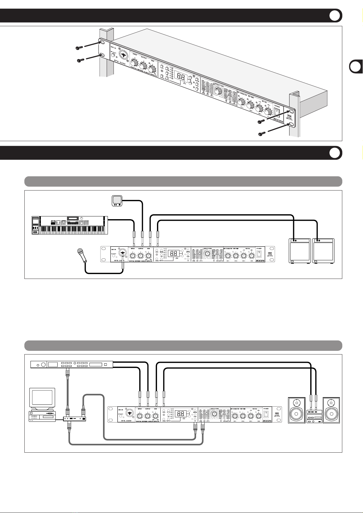
This is an example for inserting the RFX-2200 between the
sound source such as a microphone or instrument and a
playback system or multi-track recorder (MTR). A stereo
source should be connected to the INPUT L/MONO and R
jacks. A mono source should be connected to the L/MONO
jack only.
In this example, the balance between original sound and effect
sound is adjusted with the MIX control of the RFX-2200.
When a component with an S/PDIF digital input (such as a
digital multitrack recorder, MD recorder, or DAT recorder) is
used, the connection can be made in the digital domain.
This section shows how to connect the RFX-2200 to the sound source and to the playback system.
This is an example for connecting the RFX-2200 to the
send/return jacks of a mixer or multi-track recorder. Connect
the send jack of the mixer or MTR to the INPUT L/MONO
jack of the RFX-2200, and connect the OUTPUT L/R jacks of
the RFX-2200 to the return jacks (or the stereo line input
jacks) of the mixer or MTR.
When a component with an S/PDIF digital input (such as a
digital multitrack recorder, MD recorder, or DAT recorder) is
used, the connection can be made in the digital domain.
In this configuration, the MIX control of the RFX-2200 should
be set so that it outputs only the effect sound, and the balance
between original sound and effect sound should be adjusted at
the mixer or multi-track recorder. If the mixer or multi-track
recorder has a stereo send output, supplying the send signal to
the RFX-2200 in stereo is also possible.
Insert Connection
Send/Return Connection
The RFX-2200 is compatible with international 19-inch rack
standards (EIA, DIN). Because the unit has been designed for
rack installation, it is preferable to operate the unit in this
way, rather than simply placing it on a table or similar. Align
the four screw holes with the rack screw holes and securely
fasten the unit to the rack with screws.
•The RFX-2200 uses a metal frame, making
the unit heavier than it might seem at first
glance. While installing the unit in a rack,
carefully support the weight of the unit
until all screws are securely tightened.
Otherwise the unit may drop, possibly
causing injury to persons or damage to
itself or to other equipment.
•Do not directly stack the unit on top of
other equipment. Otherwise heat may
lead to a fire risk or cause performance
degradation.
•Before installation, always unplug any connecting
cables and the power cable. Otherwise the
equipment or the cables may be damaged.
•Make sure that the rack in which the unit is
installed is placed on a firm, solid surface, so that
it cannot shake or topple over. Otherwise there is
a risk of injury to persons or damage to the unit
or to other equipment.
Caution
Rack Mounting
Getting Connected
4
ZOOM RFX-2200

Using the VOCODER Effect
Controlling the RFX-2200 Effects from a Computer
*Rack mount screws are not
supplied with the unit.
MIDI IN MIDI OUT
MIDI IN
OUTPUT
R
LL
INPUT
R
MIDI
OUT
MIDI IN RFX-2200
Sound source
module
Computer
MIDI interface Playback system
In this connection example, third-party sequencer software is
used to switch patches and control parameter changes.
OUTPUT
RR
L/MONO L
INPUT
MIC IN Keyboard amplifiers
Microphone
Synthesizer
MD player or sampler or similar
with recorded voice
RFX-2200
This is a connection example for using the VOCODER effect
from the SFX bank. Plug a mic into the front-panel MIC IN
connector, and connect a synthesizer or other instrument to the
rear-panel INPUT L/MONO jack. You can then use the mic to
vary the envelope (volume change curve) and the sound
character of the VOCODER effect.
If nothing is connected to the MIC IN jack, the signal supplied
to the INPUT L/MONO jack is controlled by the signal
supplied to the INPUT R jack. Verify that the indicator of the
MIC ON/OFF switch is lit. If not, press the switch so that the
indicator comes on.
Rack Mounting
Getting Connected
Rack Mounting/Getting Connected
ZOOM RFX-2200
5
Table of contents
Other Zoom Recording Equipment manuals

Zoom
Zoom H3-VR Instructions and recipes

Zoom
Zoom H4n Pro User manual

Zoom
Zoom R20 Instructions and recipes

Zoom
Zoom 9000 User manual

Zoom
Zoom Handy REcorder H1 User manual

Zoom
Zoom H6 Handy Recorder User manual

Zoom
Zoom PodTrak P8 User manual

Zoom
Zoom GFX-707 User manual

Zoom
Zoom AMS-24 User manual

Zoom
Zoom R8 Interface User manual