Cytron MDD10A User manual

Product User’s Manual – RB-Cyt-153 (MDD10A)
MDD10A
Dual Channel 10A DC Motor Driver
User's Manual
V2.0
June 2017
Created by Cytron Technologies Sdn. Bhd. – All Rights Reserved 1

Product User’s Manual – RB-Cyt-153 (MDD10A)
INDEX
1. Introduction/Overview 3
2. Packing List 4
3. Product Specification and Limitation 5
4. Dimension 6
5. Board Layout 7
6. Getting Started 10
7. Warranty 11
Created by Cytron Technologies Sdn. Bhd. – All Rights Reserved 2

Product User’s Manual – RB-Cyt-153 (MDD10A)
1. INTRODUCTION/OVERVIEW
MDD10A is the dual channel version of MD10C which is designed to drive 2 brushed DC
motors with high current up to 10A continuously. Just like MD10C, the MDD10A also
supports locked-antiphase and sign-magnitude PWM signal. It is also using full solid state
components which result in faster response time and eliminate the wear and tear of the
mechanical relay.
* MDD10A being shipping after Jan 2017 are Rev2.0 which have upgraded to support
maximum motor voltage up to 30V.
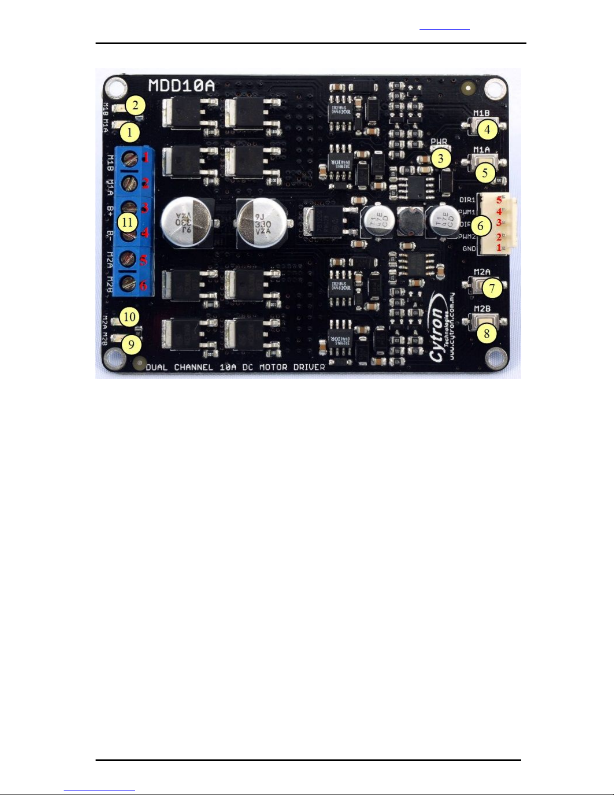
MDD10A has been designed with the capabilities and features of:
●Bi-directional control for 2 brushed DC motors.
●Support motor voltage ranges from 5V to 25V 30V (Rev2.0).
●Maximum current up to 10A continuous and 30A peak (10 second) for each channel.
●Solid state components provide faster response time and eliminate the wear and tear
of mechanical relay.
●Fully NMOS H-Bridge for better efficiency and no heat sink is required.
●Speed control PWM frequency up to 20KHz (Actual output frequency is same as
input frequency).
●Support both locked-antiphase and sign-magnitude PWM operation.
●Support TTL PWM from microcontroller, not PWM from RC receiver.
●Onboard push button to control the motor manually.
●Dimension: 84.5mm x 62mm
Note: Please use battery when driving inductive load such as DC brush motor. Due to the
protection circuit of most Power supply (switching), it will shut down when regenerative
current from motor is detected.
Created by Cytron Technologies Sdn. Bhd. – All Rights Reserved 3

Product User’s Manual – RB-Cyt-153 (MDD10A)
2. PACKING LIST
Please check the parts and components according to the packing list. If there are any parts
1. 1 x MDD10A Dual Channel 10A DC Motor Driver
2. 1 x 2510 PCB Connector - 5 Ways (Female)
3. 5 x 2510 Terminal Pin
4. User’s manual can be downloaded from the product page under Useful Links
Created by Cytron Technologies Sdn. Bhd. – All Rights Reserved 4

Product User’s Manual – RB-Cyt-153 (MDD10A)
3. PRODUCT SPECIFICATION AND LIMITATIONS
Absolute Maximum Rating
No.
Parameters
Min
Typical
Max
Unit
1
Power Input Voltage***
5
-
30
V
2
IMAX (Maximum Continuous Motor
Current)*
-
-
10
A
3
IPEAK – (Peak Motor Current) **
-
-
30
A
4
VIOH (Logic Input – High Level)
3
-
5.5
V
5
VIOL (Logic Input – Low Level)
0
0
0.5
V
6
Maximum PWM Frequency
-
-
20
KHz
* Tested in room temperature at 25°C
** Must
not
exceed
10
seconds.
***
Rev2.0
has
upgraded
to
support
30V
maximum
power
input
voltage
4. DIMENSION
Created by Cytron Technologies Sdn. Bhd. – All Rights Reserved 5

Product User’s Manual – RB-Cyt-153 (MDD10A)
5. BOARD LAYOUT
Created by Cytron Technologies Sdn. Bhd. – All Rights Reserved 6

Product User’s Manual – RB-Cyt-153 (MDD10A)
1. Red LED M1A – Turns on when the output M1A is high and output M1B is low.
Indicates the current flows from output M1A to M1B.
2. Red LED M1B – Turns on when the output M1A is low and output M1B is high.
Indicates the current flows from output M1B to M1A.
3. Green LED – Power LED. Should be on when the board is powered on.
4. Test Button M1B – When this button is pressed, current flows from output M1B to
M1A and motor will turn CCW (or CW depending on the connection).
5. Test Button M1A – When this button is pressed, current flows from output M1A to
M1B and motor will turn CW (or CCW depending on the connection).
Created by Cytron Technologies Sdn. Bhd. – All Rights Reserved 7

Product User’s Manual – RB-Cyt-153 (MDD10A)
6. Input
Pin No.
Pin Name
Description
1
GND
Ground
2
*PWM2
PWM input for speed control (Motor 2)
3
DIR2
Direction input (Motor 2)
4
*PWM1
PWM input for speed control (Motor 1)
5
DIR1
Direction input (Motor 1)
*Note that it is not for RC PWM
The truth table for the control logic for motor 1 and motor 2 are as follow:
PWM
DIR
Output A
Output B
Low
X(Don’t care)
Low
Low
High
Low
High
Low
High
High
Low
High
7. Test Button M2A – When this button is pressed, current flows from output M2A to
M2B and motor will turn CW (or CCW depending on the connection).
8. Test Button M2B – When this button is pressed, current flows from output M2B to
M2A and motor will turn CCW (or CW depending on the connection).
9. Red LED M2B – Turns on when the output M2A is low and output M2B is high.
Indicates the current flows from output M2B to M2A.
10. Red LED M2A – Turns on when the output M2A is high and output M2B is low.
Indicates the current flows from output M2A to M2B.
11. Terminal Block – Connect to motor and power source.
Pin No
Pin Name
Description
1
Motor 1 Output B
Connect to motor 1 terminal B
2
Motor 1 Output A
Connect to motor 1 terminal A
3
POWER +
Positive Supply (positive terminal of battery)
4
POWER -
Negative Supply (negative terminal of battery)
5
Motor 2 Output A
Connect to motor 2 terminal A
6
Motor 2 Output B
Connect to motor 2 terminal B
Created by Cytron Technologies Sdn. Bhd. – All Rights Reserved 8

Product User’s Manual – RB-Cyt-153 (MDD10A)
Note: Please use battery when driving inductive load such as DC brush motor. Due to the
protection circuit of most Power supply (switching), it will shut down when regenerative
current from motor is detected. Even if the case where switching power supply is needed, a
battery with the same rated voltage need to be parallel with the power supply to absorb the
regenerative current.
Created by Cytron Technologies Sdn. Bhd. – All Rights Reserved 9

Product User’s Manual – RB-Cyt-153 (MDD10A)
6. GETTING STARTED
6.1 Getting Started MDD10A with SK40C
MDD10A is compatible with 2 types of PWM operation, which are:
1. Sign-Magnitude PWM – For sign-magnitude PWM operation, 2 control signals are used to
control the speed and direction of the motor. PWM is feed to the PWM pin to control the
speed while DIR pin is used to control the direction of the motor.
2. Locked-Antiphase PWM – For locked-antiphase PWM operation, only 1 control signal is
needed to control the speed and direction of the motor. PWM pin is connected to logic high
while the DIR pin is being feed with the PWM signal. When the PWM signal has 50% duty
cycle, the motor stops running. If the PWM has less than 50% duty cycle, the motor will turn
CW (or CCW depending on the connection). If the PWM signal has more than 50% duty
cycle, motor will turn CCW (or CW depending on the connection).
6.2 Getting Started MDD10A with Arduino
Check the tutorial here for the interface of MDD10A with Arduino, example sketch can be
downloaded at the end of tutorial.
Created by Cytron Technologies Sdn. Bhd. – All Rights Reserved 10

Product User’s Manual – RB-Cyt-153 (MDD10A)
7. WARRANTY
●Product warranty is valid for 12 months.
●Warranty only applies to manufacturing defect.
●Damage caused by misuse is not covered under warranty.
●Warranty does not cover freight cost for both ways.
Prepared
by:
Cytron
Technologies
Sdn.
Bhd.
No. 1, Lorong Industri Impian 1,
Taman Industri Impian,
14000 Bukit Mertajam,
Penang, Malaysia.
Tel: +604-548
0668
Fax: +604-548
0669
URL: www.cytron.com.my
Email:
Created by Cytron Technologies Sdn. Bhd. – All Rights Reserved 11
Table of contents
Other Cytron DC Drive manuals
Popular DC Drive manuals by other brands

SEW-Eurodrive
SEW-Eurodrive MOVIMOT MM C Series Addendum to the operating instructions

Aerotech
Aerotech Automation1 iXR3 Hardware manual

Ltech
Ltech DALI DT6 manual

Danfoss
Danfoss VLT AutomationDrive FC 361 Design guide

KB Electronics
KB Electronics PENTA KB POWER KBRG-225D Installation and operating instructions

Jung
Jung TVA 230 NC WW Fitting instructions

Rockwell Automation
Rockwell Automation Allen-Bradley PowerFlex 755T Series Programming manual

gefran
gefran EXP-SFTy manual

Kanguru
Kanguru BioSlider II user manual

Parker
Parker AC15 Series Hardware installation manual

RPS
RPS TracFeed SFA manual

Franklin Electric
Franklin Electric SubDrive Connect Plus SDCP-SUB0723 quick start guide