D-Link DVG-5004 User manual


THE SPECIFICATIONS AND INFORMATION REGARDING THE PRODUCTS IN THIS MANUAL ARE
SUBJECT TO CHANGE WITHOUT NOTICE. ALL STATEMENTS, INFORMATION, AND
RECOMMENDATIONS IN THIS MANUAL ARE BELIEVED TO BE ACCURATE BUT ARE PRESENTED
WITHOUT WARRANTY OF ANY KIND, EXPRESSED OR IMPLIED. USERS MUST TAKE FULL
RESPONSIBILITIES FOR THEIR APPLICATION OF THE PRODUCTS.
THE SOFTWARE LICENSE AND LIMITED WARRANTY FOR THE ACCOMPANYING PRODUCT ARE SET
FORTH IN THE INFORMATION PACKET THAT IS SHIPPED WITH THE PRODUCT AND ARE
INCORPORATED HEREIN BY THIS REFERENCE.
NOTWITHSTANDING ANY OTHER WARRANTY HEREIN, ALL DOCUMENT FILES AND SOFTWARE OF
THESE SUPPLIERS ARE PROVIDED “AS IS” WITH ALL FAULTS. PRODUCT AND THE ABOVE-NAMED
SUPPLIERS DISCLAIM ALL WARRANTIES, EXPRESSED OR IMPLIED, INCLUDING, WITHOUT
LIMITATION, THOSE OF MERCHANTABILITY, FITNESS FOR A PARTICULAR PURPOSE AND
NONINFRINGEMENT OR ARISING FROM A COURSE OF DEALING, USAGE, OR TRADE PRACTICE.
IN NO EVENT SHALL THE PRODUCT OR ITS SUPPLIERS BE LIABLE FOR ANY INDIRECT, SPECIAL,
CONSEQUENTIAL, OR INCIDENTAL DAMAGES, INCLUDING, WITHOUT LIMITATION, LOST PROFITS OR
LOSS OR DAMAGE TO DATA ARISING FROM THE USE OR INABILITY TO USE THIS MANUAL, EVEN IF
THE PRODUCT OR ITS SUPPLIERS HAVE BEEN ADVISED OF THE POSSIBILITY OF SUCH DAMAGES.
Operation Manual
COPYRIGHT ©2005 All rights reserved.


2 SIP Operation Manual V2.6
Contents
1. Introduction....................................................................................................1
Product Overview........................................................................................................................................1
Product Features.........................................................................................................................................2
Hardware Description..................................................................................................................................3
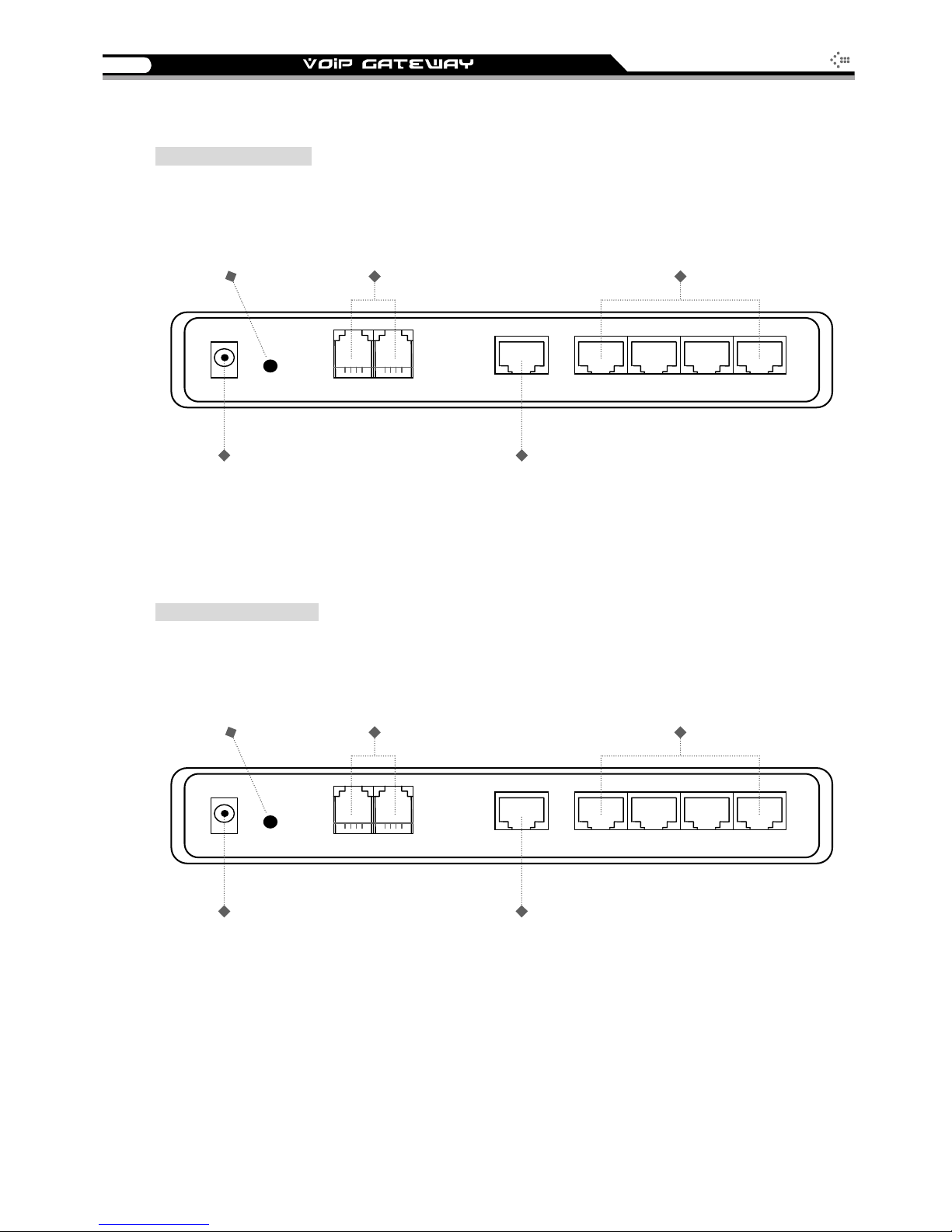
2 ports gateway model: 2S / 2O / 1S1O ........................................................................................3
4 ports gateways model: 4S / 4O / 2S2O / 3S1O ..........................................................................6
8 ports gateways model: 8S / 8O / 6S2O / 4S4O ..........................................................................9
2. Installation and Applications......................................................................12
Network Interface......................................................................................................................................12
Gateway Assigned with a Public IPAddress ...............................................................................12
Gateway in a NAT network...........................................................................................................13
Gateway assigned with a Public IPAddress and serving as an IP sharing device .....................14
Telephone Interface Description (4 ports model used in the example).....................................................15
Example for 4S gateway:.............................................................................................................15
Example for 4O gateway:.............................................................................................................16
Example for 2S2O gateway:........................................................................................................17
3. Setting the Gateway through IVR...............................................................18
IVR (Interactive Voice Response).............................................................................................................18
IVR Functions Table:....................................................................................................................20
IP Configuration Settings—Setting IP Configuration of WAN Port ..............................................22
Recorded Voice File.....................................................................................................................23
4. Setting a Gateway with WEB Browser.......................................................25
Network Settings.......................................................................................................................................26
QoS Settings.............................................................................................................................................32
NAT/DDNS................................................................................................................................................33
Telephony Settings ...................................................................................................................................34
Private Network.........................................................................................................................................37
SIP Settings ..............................................................................................................................................39
Calling Features........................................................................................................................................41
Advanced Options.....................................................................................................................................42
Line Settings ................................................................................................................................43
Voice ............................................................................................................................................43
Fax Settings.................................................................................................................................44
Digit Map...................................................................................................................................................44
Local Phone Book.....................................................................................................................................45
Speed Dial.................................................................................................................................................45
Caller Filter................................................................................................................................................45
CDR Settings ............................................................................................................................................46
Language..................................................................................................................................................46
Trunk /FXO Settings..................................................................................................................................46
Transit Call Control ...................................................................................................................................47
Long-Distance Control Table....................................................................................................................48
Long Distance Exception Table................................................................................................................49
CPT/Cadence Settings..............................................................................................................................49
CPT Auto Detect..........................................................................................................................50
Direct Connection to PSTN..........................................................................................................51
Connected to a PBX Extension Line............................................................................................52
Filling in the CPT Table................................................................................................................53
Save Settings...............................................................................................................................53
System Information...................................................................................................................................54

3
SIP Operation Manual V2.6
RTP Packet Summary...............................................................................................................................54
STUN Inquiry.............................................................................................................................................54
Ping Test...................................................................................................................................................55
Time Settings............................................................................................................................................55
System Operations (Save Settings)..........................................................................................................55
Software Upgrade.....................................................................................................................................56
Logout.......................................................................................................................................................56
5. IP Sharing Functions...................................................................................57
6. Coding Principle..........................................................................................60
Instruction..................................................................................................................................................60
Dialed Number Processing Flow...............................................................................................................60
7. Advanced Feature .......................................................................................62
Static Route※...........................................................................................................................................62
RIP(Routing Information Protocol) ※.......................................................................................................62
Port filtering...............................................................................................................................................63
IP Filtering.................................................................................................................................................63
MAC Filtering ............................................................................................................................................64
Virtual Server ............................................................................................................................................64
DMZ...........................................................................................................................................................64
URL Filter※..............................................................................................................................................65
Special Applications※...............................................................................................................................65
DoS Prevention Settings※.......................................................................................................................66
Notice................................................................................................................67

1
SIP Operation Manual V2.6
1. Introduction
Product Overview
The stand-alone VoIP Gateway carries both voice and facsimile over the IP network. It supports SIP
industry standard call control protocol to be compatible with free registration services or VoIP service
providers’ systems. It works in two different modes: UA (User Agent) or Server. As a standard user
agent, it is compatible to all well-known Soft Switches and SIP proxy servers. While running the
optional server software, the gateway can be configured to establish a private VoIP network over the
Internet without a 3rd party SIP Proxy Server.
There are 3 types of gateways in the same series: 2 ports, 4 ports and 8 ports (voice ports, FXS and/or
FXO). The gateway can be seamlessly integrated to existing network by connecting to a phone set, PBX,
key telephone system, fax machine or PSTN line. With only a broadband connection such as ADSL
bridge/router, Cable Modem or leased line router, it allows you to gain access to voice and fax services
over the IP in order to reduce the cost of international and long distance calls.
In addition, the in-built 4 ports Ethernet switch supports comprehensive Internet gateway functions to
accommodate other PCs or IP devices to share the same broadband stream. QoS function allows voice
and data traffic to flow through where voice traffic is transmitted in the highest priority. With TOS bit
enabled, it guarantees voice packets to have first priority to pass through a TOS enabled router.
With the support of DDNS, it makes the gateway reachable by its domain name where the IP address is
dynamically assigned by the ISP. It helps users to host a web site or mail server in a PPPoE or DHCP
network. By enabling the CDR function & setting up a simple server, administrators are allowed to log
in and view all call records such as call duration, time and date of calls and latency.
The gateway can be assigned with a fixed IP address or by DHCP, PPPoE. It adopts the G.711, G.726,
G.729A or G.723.1 voice compression format to save the network bandwidth while providing real-time
and toll quality voice. In addition, in the event that the power supply fails or Internet connection is lost,
the gateway can automatically divert the FXS end to the PSTN network on the FXO port so users can
still use the conventional PSTN line to make calls. This feature is especially useful while dialing
emergency calls (ie. 911).

2 SIP Operation Manual V2.6
Product Features
●SIP (RFC 3261) compliant
●Supports 2 / 4 / 8 simultaneous FAX / Voice calls (port number differs between models)
●4 Ethernet switch ports with IP sharing functions
●Optional server enables small businesses to build up private VoIP network (SIP model)
●QoS support guarantees voice bandwidth in a busy network
●Supports IP TOS (Type Of Service)
●Internet gateway functions: DHCP server, NAT, Virtual Server, DMZ, IP/PORT/MAC filtering
●T.30 (G III) / Real Time T.38 / Secured T.38 Fax Relay
●Feasible for Fixed IP address or dynamic IP address network ( PPPoE / DHCP client, support DDNS)
●Configurable Hot Line feature
●Supports IP-to-PSTN / PSTN-to-IP applications
●Life-Line support (IP / power failure over relay)
●NAT traversal - STUN and UPnP (optional)
●Pass through NAT
●Call Detailed Records (CDR)
●Web-based firmware upgrade
●Caller ID Delivery
●Easy Configuration by IVR and Web-based GUI
●Greeting message
●Echo Cancellation: G.168 compliant
●Voice Activity Detection (VAD) & Comfort Noise Generation (CNG)
●Dialing: DTMF, PULSE (optional)
●Signaling Protocol: Loop Start
●Adaptive Jitter Buffer and Programmable Gain Control
●Internet Gateway Functions : DHCP server, NAT, Virtual Server, DMZ, IP/PORT/MAC filtering
CALLfeatures (optional)
●Call hold
●Call waiting
●Call forward
- Unconditional (follow me)
- Busy forward
- No answer forward
●Call transfer

3
SIP Operation Manual V2.6
Hardware Description
2 ports gateway model: 2S / 2O / 1S1O
Front Panel
WAN, LAN indicators Voice ports indicators Status indicators
RUN
A
larmP1WANL1
VoIP Gateway
P2L2L3L4 Power
Power Indicator: Green light indicates a normal power supply.
Run Indicator: Blinking green light indicates normal operation.
Alarm Indicator: When the system starts up, the red light will blink. It also indicates the
gateway’s abnormal operation.
P1 – P2 stands for Port 1 – Port 2 (Line 1 – Line 2)
WAN stands for the WAN Port Indicator.
L1 – L4 stands for the LAN Port Indicator.
When starting up the system, theAlarm, Run, and Power indicators will light up. After
about 40 seconds, the Alarm indicator will go off, the Run indicator will blink in green, and
the Power indicator will stay green under normal operational conditions. If theAlarm
indicator continues to blink, it means the system is currently communicating with ISP and
has yet to obtain an IPaddress.
When the WAN is connected, the WAN indicator will light up in green and if data is being
transmitted over the Internet, the indicator blinks in green and orange.
Rear Panel
2S : P1-P2 are all telephone ports (FXS) to be connected to a telephone set or PBX co ports (PSTN ports).
2O : P1-P2 are line ports (FXO) to be connected to a PSTN (telephone lines from a PSTN.)
1S1O : P1 is a telephone port (FXS), and P2 is a line port (FXO). Before the power is connected or in the occasion of a
power failure, P1 will be relayed to P2 for emergency calls.
NOTE: Do not connect FXS ports to each other. Also, do not connect any FXS port directly to a
PSTN line or internal PBX. If any of these are done, your 4S may be damaged.
Please use the power adapter comes with VoIPgateway. If using adapters other than the one
comes with VoIP gateway, it may cause problems and will affect the warranty of the product.
Restore to factory default: (IP address, User’s. Name and Password)
(1) Pull off the power plug.
(2) Press reset (do not let go of the reset button).
(3) Plug the plug back into the socket (do not let go of the reset button).
(4) Let go of the reset button after 6 seconds. Factory settings will be restored.

4 SIP Operation Manual V2.6
2S Model (2 FXS ports)
LAN ports 1 ~ 4
(built-in Ethernet switch)
Connect LAN hosts here
to share WAN connection.
IP sharing features enabled
RESET
To reset the
gateway
Or to restore
factor
y
settin
g
s
FXS ports 1,2
(telephone connectors)
Phone sets connection
ports
DC+12V
2O Model (2 FXO ports)
Reset P1 WAN L1
WAN port
Connects to broadband
Networks such as ADSL,
Cable Modem or Router
POWER
Connects to the power
adapter (comes with
the gateway)
P2 L2 L3 L4
LAN ports 1 ~ 4
(built-in Ethernet switch)
Connect LAN hosts here
to share WAN connection.
IP sharing features enabled
RESET
To reset the
gateway
Or to restore
factor
y
settin
g
s
FXO ports 1 ~ 2
(PSTN line connectors)
Connect to PSTN lines
DC+12V Reset P1 WAN L1
WAN port
Connects to broadband
Networks such as ADSL,
Cable Modem or Router
POWER
Connects to the power
adapter (comes with
the gateway)
L3 L4L2P2

5
SIP Operation Manual V2.6
1S1O Model (1 FXO and 1 FXS ports)
FXS port : 1
FXO port : 2
FXS connects to phone set;
FXO connect to PSTN line
LAN ports 1 ~ 4
(built-in Ethernet switch)
Connect LAN hosts here
to share WAN connection.
IP sharing features enabled
RESET
To reset the
gateway
Or to restore
factor
y
settin
g
s
DC+12V Reset P1 WAN L1
WAN port
Connects to broadband
Networks such as ADSL,
Cable Modem or Router
POWER
Connect to the power
adapter (comes with
the gateway)
L3 L4L2P2

6 SIP Operation Manual V2.6
4 ports gateways model: 4S / 4O / 2S2O / 3S1O
Front Panel
WAN, LAN indicators Voice ports indicators Status indicators
RUN
A
larmP1WANL1
VoIP Gateway
P2P3P4L2L3L4 Power
Power Indicator: Green light indicates a normal power supply.
Run Indicator: Blinking green light indicates normal operation.
Alarm Indicator: When the system starts up, the red light will blink. It also indicates the
gateway’s abnormal operation.
P1 – P4 stands for Port 1 – Port 4 (Line 1 – Line 4)
WAN stands for the WAN Port Indicator.
L1 – L4 stands for the LAN Port Indicator.
When starting up the system, theAlarm, Run, and Power indicators will light up. After
about 15 seconds, the Alarm indicator will go off, the Run indicator will blink in green, and
the Power indicator will stay green under operational conditions. If theAlarm indicator
continues to blink, it means the system is currently communicating with ISPand has yet to
obtain an IPaddress.
When the WAN is connected, the WAN indicator will lights up in green and if data is being
transmitted over the Internet, the indicator blinks in green and orange.
Rear Panel
4S : P1-P4 are telephone ports (FXS) to be connected to a telephone set or PBX co ports (PSTN ports).
4O : P1-P4 are line ports (FXO) to be connected to a PSTN (telephone lines from a PSTN.)
2S2O : P1-P2 are telephone ports (FXS), and P3-P4 are line ports (FXO). Before the power is connected or in the
occasion of a power failure, P1 will be relayed to P3, and P2 to P4 to reach PSTN.
3S1O : P1-P3 are telephone ports (FXS), and P4 is a line port (FXO). Before the power is connected or in the
occasion of a power failure, P1 will be relayed to P4 so that emergency calls can be made.
NOTE: Do not connect FXS ports to each other. Also, do not connect any FXS port directly to a
PSTN line or internal PBX. If any of these are done, your 4S may be damaged.
Please use the power adapter comes with VoIP gateway. If using adapters other than the one
comes with VoIP gateway, it may cause problems and will affect the warranty of the product.
Restore to factory default: (IP address, User’s. Name and Password)
(1) Pull off the power plug.
(2) Press reset (do not let go of the reset button).
(3) Plug the plug back into the socket (do not let go of the reset button).
(4) Let go of the reset button after 6 seconds. Factory settings will be restored.

7
SIP Operation Manual V2.6
4S Model (4 FXS ports)
FXS ports 1 ~ 4
(telephone connectors)
Connecst to phone sets
LAN ports 1 ~ 4
(built-in Ethernet switch)
Connect LAN hosts here
to share WAN connection.
IP sharing features enabled
RESET
To reset the
gateway or to
restore
factor
y
settin
g
s
DC+12V Reset P1 WAN L1
WAN port
Connects to broadband
Networks such as ADSL,
Cable Modem or Router
POWER
Connects to the power
adapter (comes with
the gateway)
L4L3L2P4P3P2
4O Model (4 FXO ports)
FXO ports 1 ~ 4
(PSTN line connectors)
Connects to PSTN lines
LAN ports 1 ~ 4
(built-in Ethernet switch)
Connect LAN hosts here
to share WAN connection.
IP sharing features enabled
RESET
To reset the
gateway
or to restore
factor
y
settin
g
s
DC+12V Reset P1 WAN L1
WAN port
Connects to broadband
Networks such as ADSL,
Cable Modem or Router
POWER
Connects to the power
adapter (comes with
the gateway)
L4L3L2P4P3P2

8 SIP Operation Manual V2.6
2S2O Model (2 FXS and 2 FXO ports)
FXS ports 1,2
FXO ports 3,4
FXS to telephone set;
FXO to PSTN lines
LAN ports 1 ~ 4
(built-in Ethernet switch)
Connect LAN hosts here
to share WAN connection.
IP sharing features enabled
RESET
To reset the
gateway
Or to restore
factor
y
settin
g
s
DC+12V Reset P1 WAN L1
WAN port
Connects to broadband
Networks such as ADSL,
Cable Modem or Router
POWER
Connects to the power
adapter (comes with
the gateway)
L4L3L2P4P3P2
3S1O Model (3 FXS and 1 FXO ports)
FXS ports : 1, 2, 3
FXO ports : 4
FXS to telephone set;
FXO to PSTN lines
LAN ports 1 ~ 4
(built-in Ethernet switch)
Connect LAN hosts here
to share WAN connection.
IP sharing features enabled
RESET
To reset the
gateway
Or to restore
factor
y
settin
g
s
DC+12V Reset P1 WAN L1
WAN port
Connects to broadband
Networks such as ADSL,
Cable Modem or Router
POWER
Connectsto the power
adapter (comes with
the gateway)
L4L3L2P4P3P2

9
SIP Operation Manual V2.6
8 ports gateways model: 8S / 8O / 6S2O / 4S4O
Front Panel
Voice ports indicators WAN, LAN indicators Status indicators
P4 P3 P2 P1 Power
L4 L3 L2
P6P8 P7
VoIP Gatewa
y
L1 WAN
P5
A
larm RUN
Power Indicator: Green light indicates a normal power supply.
Run Indicator: Blinking green light indicates normal operation.
Alarm Indicator: When the system starts up, the red light will blink. It also indicates the
gateway’s abnormal operation.
P1 – P8 stands for Port 1 – Port 8 (Line 1 – Line 8)
WAN stands for the WAN Port Indicator.
L1 – L4 stands for the LAN Port Indicator.
When starting up the system, theAlarm, Run, and Power indicators will light up. After
about 15 seconds, the Alarm indicator will go off, the Run indicator will blink in green, and
the Power indicator will stay green under operational conditions. If theAlarm indicator
continues to blink, it means the system is currently communicating with ISPand has yet to
obtain an IPaddress.
When the ethereal cable is connected, the Link indicator will light up and if data is being
transmitted over the Internet, the act indicator will blink.
Rear Panel
8S : P1-P8 are telephone ports (FXS) to be connected to a telephone set or PBX CO ports (PSTN ports).
8O : P1-P8 are line ports (FXO) to be connected to a PSTN (telephone lines from a PSTN.)
6S2O : P1-P6 are telephone ports (FXS), and P7-P8 are line ports (FXO). Before the power is connected or in the
occasion of a power failure, P1 will be relayed to P7, and P2 relayed to P8 to reach PSTN.
4S4O : P1-P4 are telephone ports (FXS), and P5-P8 are line ports (FXO). Before the power is connected or in the
occasion of a power failure, P1 will be relayed to P5, P2 relayed to P6, P3 relayed to P7, and P4 relayed to P8 to
reach PSTN.
NOTE: Do not connect FXS ports to each other. Also, do not connect any FXS port directly to a
PSTN line or internal PBX. If any of these are done, your 4S may be damaged.
Please use the power adapter comes with VoIP gateway. If using adapters other than the one
comes with VoIP gateway, it may cause problems and will affect the warranty of the product.
Restore to factory default: (IP address, User’s. Name and Password)
(1) Pull off the power plug.
(2) Press reset (do not let go of the reset button).
(3) Plug the plug back into the socket (do not let go of the reset button).
(4) Let go of the reset button after 6 seconds. Factory settings will be restored.

10 SIP Operation Manual V2.6
8S Model (8 FXS ports)
LAN ports 1 ~ 4
(built-in Ethernet switch)
Connect LAN hosts here
to share WAN connection.
IP sharing features enabled
RESET
To reset the
gateway
Or to restore
factory settings
FXS ports 1 ~ 8
(telephone connectors)
Connects to phone sets
8O Model (8 FXO ports)
POWER
Connects to the power
Adapter (comes with
the gateway)
P1
WAN L1
WAN port
Connects to broadband
Networks such as ADSL,
Cable Modem or Router
P2 P3 P4
L2 L3 L4
RESET GND DC12V
P7 P8
P5 P6
POWER
Connects to the power
adapter (comes with
the gateway)
P1
WAN L1
FXO ports 1 ~ 8
(PSTN line connectors)
Connects to PSTN lines
WAN port
Connects to broadband
Networks such as ADSL,
Cable Modem or Router
LAN ports 1 ~ 4
(built-in Ethernet switch)
Connect LAN hosts here
to share WAN connection.
IP sharing features enabled
RESET
To reset the
gateway
or to restore
factory settings
P2 P3 P4
L2 L3 L4 DC12VGND
RESET P7 P8
P6
P5

11
SIP Operation Manual V2.6
6S2O Model (6 FXS and 2 FXO ports)
POWER
Connects to the power
adapter (comes with
the gateway)
P1
WAN L1
FXS ports 1 ~ 6
(telephone connectors)
Connects to phone sets
WAN port
Connecst to broadband
Networks such as ADSL,
Cable Modem or Router
LAN ports 1 ~ 4
(built-in Ethernet switch)
Connect LAN hosts here
to share WAN connection.
IP sharing features enabled
RESET
To reset the
gateway
or to restore
factory settings
P2 P3 P4
L2 L3 L4 DC12VGND
RESET P7 P8
P6
P5
FXO ports 7,8
(PSTN line connectors)
Connects to PSTN lines
4S4O Model (4 FXS and 4 FXO ports)
POWER
Connects to the power
adapter (comes with
the gateway)
P1
WAN L1
FXS ports 1 ~ 4
(telephone connectors)
Connects to phone sets
WAN port
Connects to broadband
Networks such as ADSL,
Cable Modem or Router
LAN ports 1 ~ 4
(built-in Ethernet switch)
Connect LAN hosts here
to share WAN connection.
IP sharing features enabled
RESET
To reset the
gateway
or to restore
factory settings
P2 P3 P4
L2 L3 L4
FXO ports 5~8
(PSTN line connectors)
Connects to PSTN lines
DC12VGND
RESET P7 P8
P6
P5

12 SIP Operation Manual V2.6
2. Installation and Applications
Network Interface
The network interface is divided into 3 basic modes as described below:
Gateway can be assigned with a Public IP Address
Gateway can be built under the existing NAT
Gateway can be assigned with a Public IP address and serves as an IP sharing router.
Gateway Assigned with a Public IP Address
The gateway will have a Public IP address for Internet connection regardless of whether it is a static IP
address, DHCP (using a Cable Modem), or PPPoE (Dialup / ADSL).
Gateway IP Settings Need to be set up as static IP,
DHCP, or PPPoE
NAT/STUN Settings Unnecessary (Disabled)
DDNS Settings Unnecessary (Disabled)
Leased line / ADSL / Cable modem
InternetInternet
PBX
Phone Phone
WAN

13
SIP Operation Manual V2.6
Gateway in a NAT network
The gateway uses a virtual IP address and the IP sharing function of other systems to connect to the
Internet.
LAN IP address of IP sharing Please avoid IP address 192.168.0.1-192.168.8.254 (You may need to
change the settings of IP sharing or change SIP series Gateway LAN Port IP
address)
Gateway IP Settings Set as static IP address, and assign the LAN IP address of the IP sharing to
the Default Gateway.
If the WAN of the IP sharing device has static IP address, then
the NAT IP address is set as the Public IP address of the IP
sharing.
NAT /STUN Settings
Please refer to P. 29 for the Use NAT.
Enable
If the WAN of the IP sharing device uses a dynamic IP address,
then it has to comply with the DDNS settings. When suing
NAT, you must enter the URL (Uniform Resource Locator) that
is registered to the DDNS server.
The WAN of the IP
sharing device has a static
IP address.
Disabled
DDNS Settings
Please refer to P. 29 for the DDNS
Settings
The WAN of the IP
sharing device has a
dynamic IP address.
Enabled: enter the registered URL (Uniform
Resource Locator) into the network settings ->
under NAT
Leased line / ADSL / Cable modem
InternetInternet
Firewall / NAT
PC
PC
PC
PBX
Phone Phone
WAN

14 SIP Operation Manual V2.6
Gateway assigned with a Public IP Address and serving as an IP sharing device
The gateway will have a Public IP address regardless of whether it is a static IP application, DHCP
(using a Cable Modem), or PPPoE (To connect to your ADSL account), which can then use the
functions of built-in IP sharing function to allow other PCs to be on-line at the same time.
Gateway IP Settings Need to be set up as static IP, DHCP, or
PPPoE
NAT/STUN Settings Unnecessary (Disabled)
DDNS Settings Unnecessary (Disabled)
For settings at PC end, please
refer to section “IP sharing
functions”
PC uses a static IP address ranging from:
192.168.8.1-192.168.8.253
Subnet Mask:255.255.255.0
Default Gateway:192.168.8.254
Leased line / ADSL / Cable modem
InternetInternet
PC PC PC
VoIP gateway serving as an IP sharing device
PBX
Phone
Phone
WAN
LAN
This manual suits for next models
1
Table of contents
Other D-Link VoIP manuals
Popular VoIP manuals by other brands

XtendLan
XtendLan GONU14RS user guide

iPECS
iPECS eMG80 Hardware description & installation manual

Tema Telecomunicazioni
Tema Telecomunicazioni AD639R product manual

Media5
Media5 Mediatrix 4108iPBX installation guide

Avaya
Avaya Tandberg 150 MXP installation instructions

Altesys
Altesys Micro VoIP 200 user manual