D-Link DVG-N5402SP User manual

DVG-N5402SP
VoIP Wireless Router
User’s Manual
Version 1.0
(Feb. 2011)

© 2011 D-Link Corporation. All rights reserved.
Reproduction in any manner whatsoever without the written permission of D-Link Corporation is strictly forbidden.
Trademarks used in this text: D-Link and the D-Link logo are trademarks of D-Link Corporation/D-Link Systems
Inc.; Other trademarks and trade names may be used in this document to refer to either the entities claiming the
marks and names or their products. D-Link Corporation disclaims any proprietary interest in trademarks and trade
names other than its own.
Warranty: please contact your D-Link Authorized Reseller or the D-Link Branch Office nearest your place of
purchase for information about the warranty offered on your D-Link product.
Information in this document is subject to change without notice.
FCC Warning
This equipment has been tested and found to comply with the limits for a Class B digital device, pursuant to Part 15
of the FCC Rules. These limits are designed to provide reasonable protection against harmful interference in a
residential installation. This equipment generates, uses, and can radiate radio frequency energy and, if not installed
and used in accordance with the instructions, may cause harmful interference to radio communication. However,
there is no guarantee that interference will not occur in a particular installation. If this equipment does cause harmful
interference to radio or television reception, which can be determined by turning the equipment off and on, the user
is encouraged to try to correct the interference by one or more of the following measures:
‧Reorient or relocate the receiving antenna.
‧Increase the separation between the equipment and receiver.
‧Connect the equipment into an outlet on a circuit different from that to which the receiver is connected.
‧Consult the dealer or an experienced radio/TV technician for help.
CE Mark Warning
This is a Class B product. In a domestic environment, this product may cause radio interference in which case the
user may be required to take adequate measures.
Warnung!
Dies ist ein Produkt der Klasse B. Im Wohnbereich kann dieses Produkt Funkstoerungen verursachen. In diesem
Fall kann vom Benutzer verlangt werden, angemessene Massnahmen zu ergreifen.
Precaución!
Este es un producto de Clase B. En un entorno doméstico, puede causar interferencias de radio, en cuyo case, puede
requerirse al usuario para que adopte las medidas adecuadas.
Attention!
Ceci est un produit de classe B. Dans un environnement domestique, ce produit pourrait causer des interférences
radio, auquel cas l`utilisateur devrait prendre les mesures adéquates.
Attenzione!
Il presente prodotto appartiene alla classe B. Se utilizzato in ambiente domestico il prodotto può causare interferenze
radio, nel cui caso è possibile che l`utente debba assumere provvedimenti adeguati.

Contents
1. Introduction .....................................................................................................................................................4
1-1 Product Overview.....................................................................................................................................4
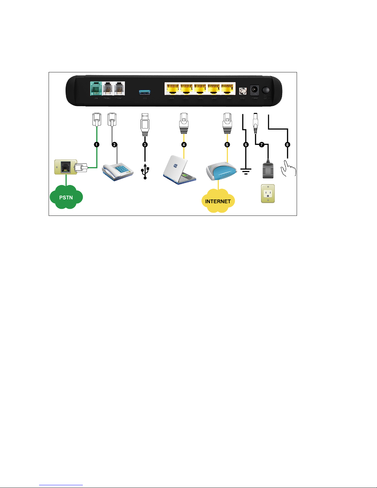
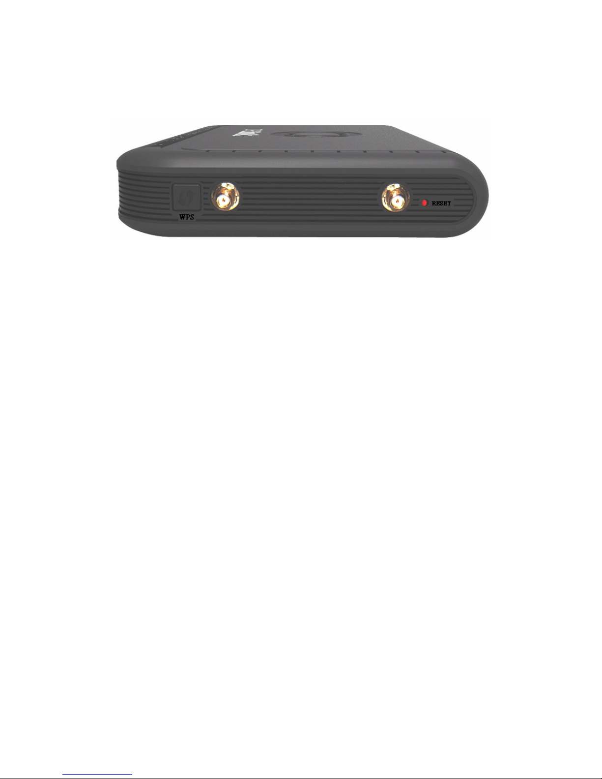
1-2 Hardware Description...............................................................................................................................5
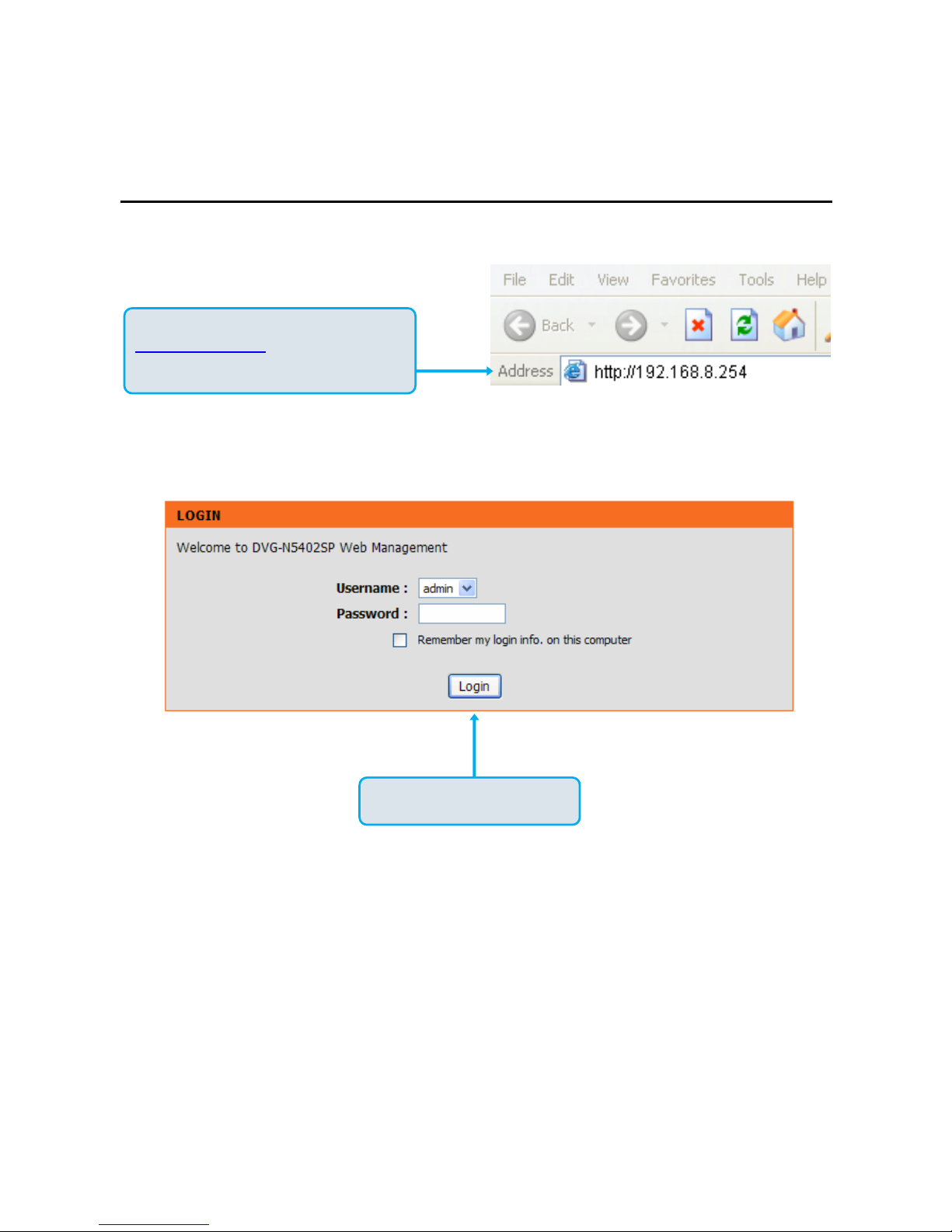
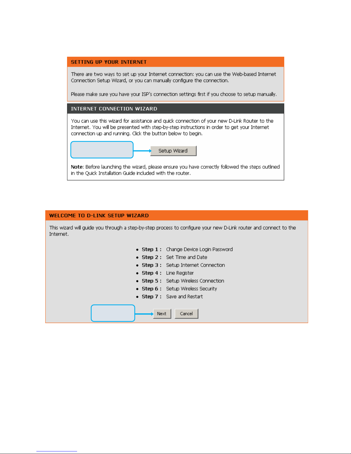
2. Getting Started ................................................................................................................................................8
3. VoIP Router Web Configuration ...................................................................................................................16
3-1 SETUP...................................................................................................................................................16
3-1-1 Internet Setup ..............................................................................................................................16
3-1-2 VoIP Setup...................................................................................................................................22
3-1-3 Wireless Setup.............................................................................................................................28
3-1-4 LAN Setup ...................................................................................................................................39
3-1-5 USB Settings ...............................................................................................................................42
3-1-6 Time and Date .............................................................................................................................43
3-2 ADVANCED ...........................................................................................................................................44
3-2-1 VoIP .............................................................................................................................................44
3-2-2 Access Control.............................................................................................................................73
3-2-3 Firewall and DMZ.........................................................................................................................74
3-2-4 Advanced Wireless ......................................................................................................................79
3-2-5 Advanced Network.......................................................................................................................81
3-2-6 SNMP ..........................................................................................................................................86
3-3 MAINTENANCE.....................................................................................................................................89
3-3-1 Device Management....................................................................................................................89
3-3-2 Backup and Restore ....................................................................................................................90
3-3-3 Firmware Update .........................................................................................................................92
3-3-4 Dynamic DNS ..............................................................................................................................93
3-3-5 Log Settings.................................................................................................................................94
3-3-6 Diagnostics ..................................................................................................................................95
3-3-7 TR069..........................................................................................................................................98
3-3-8 CDR...........................................................................................................................................100
3-4 STATUS...............................................................................................................................................101
3-4-1 Device Info.................................................................................................................................101
3-4-2 VoIP Status ................................................................................................................................102
3-4-3 LAN Client .................................................................................................................................103
3-4-4 Statistics ....................................................................................................................................104
3-4-5 Routing Table.............................................................................................................................104
3-4-6 Logout........................................................................................................................................105
4. Configuring the VoIP Router through IVR .................................................................................................106
4-1 IVR (Interactive Voice Response) ........................................................................................................106
4-2 IP Configuration Settings—Set the IP Configuration of the WAN Port..................................................109
5. Dialing Principles ........................................................................................................................................ 112
5-1 Dialing Options.....................................................................................................................................112
5-2 Number Translation..............................................................................................................................112
5-3 Routing ................................................................................................................................................113
Appendix.......................................................................................................................................................... 115
Product Features........................................................................................................................................115

DVG-N5402SPUser’sManual ProductOverview
D-Link Systems, Inc. 4
1. Introduction
1-1 Product Overview
The DVG-N5402SP is designed to carry both voice and facsimile over the IP network and wirelessly share
Internet access. It uses the industry standard SIP call control protocol so as to be compatible with free registration
services or VoIP service providers’ systems. As a standard user agent, it is compatible with all common Soft
Switches and SIP proxy servers. While running optional server software, the VoIP Router can be configured to
establish a private VoIP network over the Internet without a third-party SIP Proxy Server.
The DVG-N5402SP can be seamlessly integrated into an existing network by connecting to a phone set and fax
machine. With only a broadband connection such as an ADSL bridge/router, a Cable Modem or a leased-line
router, the VoIP Router allows you to use voice and fax services over IP in order to reduce the cost of all long
distance calls.
The DVG-N5402SP is also an 802.11b/g/n wireless access point. Allow wireless clients to connect to it and share
your broadband Internet connection. A built-in 4-port switch makes it possible to connect up to 4 Ethernet-enabled
computers or devices to also share your Internet connection.
The DVG-N5402SP can be configured a fixed IP address or it can have one dynamically assigned by DHCP or
PPPoE. It adopts either the G.711, G.726, G.729A, G.723.1 or iLBC voice compression format to save network
bandwidth while providing real-time, toll quality voice transmission and reception.

DVG-N5402SP User’s Manual Telephone Interface Description
D-Link Systems, Inc. 5
1-2 Hardware Description
Front Panel
Power: Power LED. A steady light indicates a proper connection to a power source.
Prov./Alm.: A blinking light indicates the DVG-N5402SP can not register with SIP Server or can not get the
IP address. A blinking light also indicates the DVG-N5402SP is attempting to connect with the Provisioning
server. Once the service connects, the LED will turn off. The LED will light solid red if the self-test or boot-up
fails.
Reg.: The Register LED will turn on and continuously working when DVG-N5402SP is connected to a VoIP
service provider. The LED will flash if not connected to a service provider.
WAN: When a connection is established the LED will light up solid. The LED will blink to indicate activity. If
the LED does not light up when a cable is connected, verify the cable connections and make sure your
devices are powered on.
WLAN: A steady light indicates a wireless connection. A blinking light indicates that the VoIP Router is
receiving/transmitting from/to the wireless network.
LAN: When a connection is established the LED (bottom) will light up solid on the appropriate port. The
LEDs will blink to indicate activity. If the LED does not light up when a cable is connected, verify the cable
connections and make sure your devices are powered on.
USB: This indicates that DVG-N5402SP detects a supported 3G modem dungle or a USB device.
Phone: This LED displays the VoIP status and Hook/Ringing activity on the phone port that is used to
connect your normal telephone(s). If a phone connected to a phone port is off the hook or in use, this LED
will light solid. When a phone is ringing, the indicator will blink.
Line: Light on means the line is in use (off-hook), and vice versa.
WPS: Flashing in blue as DVG-N5402SP processing WPS-PCB wireless connecting progress.

DVG-N5402SP User’s Manual Telephone Interface Description
D-Link Systems, Inc. 6
Rear Panel
1. Line: Connect to your original telephone line on the wall jack with RJ-11 cable.
2. Phone Port (1-2): Connect to your phones using standard phone cabling (RJ-11).
3. USB: Connect to a 3G USB dungle or a printer.
4. LAN: Connect to your Ethernet enabled computers using Ethernet cabling.
5. WAN: Connect to your broadband modem using an Ethernet cable.
6. Ground: A conducting connection with the earth. Connect with the ground so as to make the earth a part of
an electrical circuit using metal wire.
7. Power Receptor: Receptor for the provided power adapter.
8. Power Switch: Press down to turn-on DVG-N5402SP.
WARNING: DO NOT (1) connect the phone ports to each other (FXS to FXS) or (2) connect any
phone port directly to a PSTN line (FXS to PSTN) or to an internal PBX line (FXS to PBX extension).
(3) Stacking is forbidden. Doing so may damage your VoIP Router.

DVG-N5402SP User’s Manual Telephone Interface Description
D-Link Systems, Inc. 7
WPS: WPS button for wireless WPS-PCB setup method.
Antenna: Connect to a wireless network.
Reset button: Use to restore factory default settings.
Use Reset Button to restore factory default settings:
1. Press and hold the reset button for 5 seconds.
2. As Alarm indicator is blinking, please release the reset button. Factory settings will be
restored.

DVG-N5402SPUser’sManual SETUP
D-Link Systems, Inc. 8
2. Getting Started
To access the web-based configuration utility, open a web browser such as Internet Explorer and enter the IP
address of the DVG-N5402SP from WAN port.
Open your Web browser and type
http://192.168.8.254 into the URL address
box. Press the Enter or Return Key.
Click Login to enter Web Site.

DVG-N5402SPUser’sManual SETUP
D-Link Systems, Inc. 9
Click Setup Wizard.
Click Next.

DVG-N5402SPUser’sManual SETUP
D-Link Systems, Inc. 10
The username of ADMIN and USER have
been defined and locked by default. It is
highly recommended to create a login
password to keep your VoIP Router
secure.
Click Next.

DVG-N5402SPUser’sManual SETUP
D-Link Systems, Inc. 11
Enter a NTP server or use the default
server. Select your time zone from the
drop-down menu. Enable Daylight Saving
for your local time if required.
Click Next.

DVG-N5402SPUser’sManual SETUP
D-Link Systems, Inc. 12
Select your Internet connection type:
DHCP – Most Cable ISPs or if you are connecting the DVG-N5402SP behind a router.
Static IP – Select if your ISP supplied you with your IP settings.
PPPoE – Most DSL ISPs.
PPTP – Select if required by your ISP.
3G USB Adapter – Select it for 3G WISP.
WAN1 Domain Name Server – Select Manual to manually enter IP address of DNS or select Auto
if DNS is assigned by ISP.
Click Next.

DVG-N5402SPUser’sManual SETUP
D-Link Systems, Inc. 13
Register to the SIP Proxy Server by clicking Enable support of SIP Proxy Server. Enter Proxy Server IP/Domain
and Port.
Outbound Proxy Support is optional. To register, please click on the Outbound Proxy Support box and enter
Outbound Proxy IP/Domain and Port in it.
Registration by phone line: Enter Number, User ID/Account and Password supplied by your ITSP. Check on the
Register box to register to Proxy Server.
Click Next.

DVG-N5402SPUser’sManual SETUP
D-Link Systems, Inc. 14
Click on the Enable wireless LAN interface check box to build a wireless network. Enter the SSID to
name your wireless network. All devices must have the same SSID to communicate on the wireless
network. Select a clear wireless channel. Select the 802.11 Mode of your network which can work in
different speed of wireless connection.
Click Next.
Select Security Mode for your wireless
network.
Click Next.

DVG-N5402SPUser’sManual SETUP
D-Link Systems, Inc. 15
Setup is finished. Check the summary of your
settings. To make new settings effective, you
must click on the Restart button to reboot the
DVG-N5402SP.
Click Restart.

DVG-N5402SPUser’sManual SETUP
D-Link Systems, Inc. 16
3. VoIP Router Web Configuration
3-1 SETUP
3-1-1 Internet Setup
WAN (Wide Area Network) Settings are used to connect to your ISP (Internet Service Provider). The WAN
settings are provided to you by your ISP and oftentimes referred to as "public settings". Please select the
appropriate option for your specific ISP.
IP Configuration (Setting WAN Port)
There are five methods of obtaining a WAN port IP address:
1. DHCP, which means a Dynamic IP (Cable Modem)
2. Static IP
3. PPPoE (dial-up ADSL)
4. PPTP
5. 3G USB Adapter
Methods for using DHCP and PPPoE for obtaining an IP address may vary. If you are not familiar with
creating a network connection, please contact your local ISP.
After selecting the suitable option, click Accept at the bottom of the screen to save the settings.
You need to save the changes and restart the VoIP Router to make the changes active. Saving the settings:
Click MAINTENANCE and select Save/Restart in Backup and Restore from the left menu. Tick Save
Settings and Restart, and then click Accept. Wait for about 40 seconds before the VoIP Router obtaining
an IP address by the method you selected.
Note: When the system has obtained a new IP address, and you are using a WAN port to enter the Web
Configuration Screen, the new IP address has to be used before you can get connected to the VoIP Router.
The same principle applies to the next two settings.

DVG-N5402SPUser’sManual SETUP
D-Link Systems, Inc. 17
SETUP →Internet Setup
DHCP: Select this option if your ISP (Internet Service Provider) provides you an IP address automatically.
Cable modem providers typically use dynamic assignment of IP Address. The Host Name field is optional
but may be required by some Internet Service Providers.
SETUP →Internet Setup
Static IP: Select this option if your ISP (Internet Service Provider) provides you a Static IP address. Enter
the IP address, Subnet Mask and Default Gateway IP.

DVG-N5402SPUser’sManual SETUP
D-Link Systems, Inc. 18
SETUP →Internet Setup
PPPoE: Select this option if your ISP requires you to use a PPPoE (Point-to-Point Protocol over Ethernet)
connection. Enter the PPPoE Account, PPPoE Password and re-enter Password to confirm.
SETUP →Internet Setup
PPTP: Point-to-Point Tunneling Protocol (PPTP) is a WAN connection. Enter the IP Address, Subnet
mask, PPTP Server, PPTP ID and Password.

DVG-N5402SPUser’sManual SETUP
D-Link Systems, Inc. 19
SETUP →Internet Setup
3G USB Adapter: 3G/3.5G WISP. Enter Username, Password, Dial Number and APN to connect to
Internet via 3G/3.5G WISP. Users could also select a configured WISP from the list and DVG-N5402SP will
fill necessary parameter automatically.
SETUP →Internet Setup
WAN Link Speed: Select WAN port link speed.
SETUP →Internet Setup
VoIP Connection Interface: Select a WAN interface for DVG-N5402SP VoIP traffic.

DVG-N5402SPUser’sManual SETUP
D-Link Systems, Inc. 20
SETUP →Internet Setup
Factory Default MAC Address: The original MAC address of the VoIP Router.
Your MAC Address: It is left blank as you log-in via the WAN port.
Current MAC Address: It shows the current MAC Address if you ever used the different MAC address
from Factory Default MAC Address. You can click Clone to automatically copy the MAC address of the
Ethernet Card installed in the computer used to configure the device.
Note: This is only necessary to fill the field if required by your ISP.
SETUP →Internet Setup
Click “Advanced Configuration” for 802.11q/p VLAN tag or dual WAN access configuration.
Other manuals for DVG-N5402SP
4
Table of contents
Other D-Link Wireless Router manuals

D-Link
D-Link DAP-1350 User manual

D-Link
D-Link DIR-300A User manual

D-Link
D-Link DWR-116 User manual

D-Link
D-Link DSL-7850U User manual

D-Link
D-Link DI-634M User manual

D-Link
D-Link DWR-116 User manual

D-Link
D-Link DWR-M920 User manual

D-Link
D-Link DIR-1950 User manual

D-Link
D-Link DSR-500N User manual

D-Link
D-Link DIR-510L User manual

D-Link
D-Link DSL-2750U User manual

D-Link
D-Link DSL-G624T User manual

D-Link
D-Link DWR-978 User manual

D-Link
D-Link GO-DSL-N150 User manual

D-Link
D-Link DI-713P User manual

D-Link
D-Link DIR-320 User manual

D-Link
D-Link DSL-G225 User manual

D-Link
D-Link DSL-2740R User manual

D-Link
D-Link DIR-868L User manual

D-Link
D-Link DWR-730 User manual