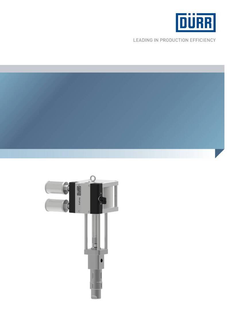
DÖRR EcoPump AD Package User manual

MPU00015EN, V04
Translation of the original operation manual
© Dürr Systems AG 2016
Dürr Systems AG
Application Technology
Carl-Benz-Str. 34
74321 Bietigheim-Bissingen
Germany
Phone +49 7142 78-0
Internet: www.durr.com
The reproduction and distribution of this document, use and communication of its contents are not permitted
without express written approval. Offenders will be liable for damages. All rights in the event of a patent grant
or design registration are reserved.
12/2019EcoPump AD Package - MPU00015EN
2/40

Information about the document
This document describes the correct handling of
the product.
Read the document prior to every activity.
Prepare the document for the application.
Pass on the product only together with the com-
plete documentation.
Always follow safety instructions, handling
instructions and specifications of every kind.
Illustrations can deviate from the technical con-
struction.
Validity range of the document
N92120001V
EcoPump AD Package
Applicable documents
MPU00006* - EcoPump AD 150 7 ACE 1/2"
MPU00008* - EcoPump AD 72 8 ACE 1/4"
MPU00009* - EcoPump AD 83 7 ACE 3/8"
MPU00010* - EcoPump AD 150 7 SST 1/2"
EcoPump AD 150 7 ALU 1/2"
MFT00003* - Filter HP
MRE00007* - EcoFlow LPF M
An asterisk (*) in the document number
replaces the symbol of the language variant.
Hotline and Contact
If you have queries or would like technical informa-
tion, please contact your dealer or sales partner.
12/2019 EcoPump AD Package - MPU00015EN 3/40

TABLE OF CONTENTS
1 Product overview...................................... 5
1.1 Overview............................................. 5
1.2 Short description................................. 5
2 Safety.......................................................... 5
2.1 Presentation of Notes.......................... 5
2.2 Intended Use....................................... 5
2.3 Residual risks...................................... 6
2.4 Conduct in the event of a hazardous
situation............................................... 7
2.5 Staff qualification................................. 7
2.6 Personal protective equipment............ 7
3 Design and Function................................. 8
3.1 System................................................ 8
3.2 Pumping.............................................. 8
3.3 Pneumatic maintenance unit for com-
pressed air preparation....................... 9
3.4 Suction module.................................... 9
3.5 Filter.................................................. 10
3.6 Distributor block................................. 10
3.7 Ball valve........................................... 10
3.8 Material pressure regulator................ 11
3.9 Transportation module....................... 11
4 Transport, scope of supply and
storage...................................................... 11
4.1 Scope of delivery............................... 11
4.2 Handling of packaging material......... 11
4.3 Storage.............................................. 11
4.4 Transport........................................... 12
5 Assembly................................................. 12
5.1 Requirements for the
Installation point................................ 12
5.2 Assembly........................................... 12
5.3 Connecting........................................ 13
5.4 Assembling ground conductor........... 14
6 Commissioning....................................... 15
6.1 Safety Instructions............................. 15
6.2 Commissioning.................................. 15
7 Operation................................................. 17
7.1 Safety recommendations................... 17
7.2 General notes.................................... 17
7.3 Switching on...................................... 18
7.4 Switching off...................................... 19
7.5 Rinsing.............................................. 20
8 Cleaning................................................... 21
8.1 Safety recommendations .................. 21
8.2 Cleaning............................................ 22
9 Maintenance............................................. 23
9.1 Safety recommendations................... 23
9.2 Maintenance schedule...................... 23
9.3 Replace filter of the maintenance
unit..................................................... 24
9.4 Replacing filter disk........................... 25
9.5 Replace filter cartridge...................... 25
9.6 Dismantling........................................ 26
9.7 Assembly........................................... 28
10 Faults........................................................ 30
10.1 Behavior during faults...................... 30
10.2 Defects table................................... 31
11 Disassembly and Disposal..................... 31
11.1 Safety recommendations................. 31
11.2 Disassembly.................................... 32
11.3 Disposal .......................................... 32
12 Technical data.......................................... 32
12.1 Dimensions and weight................... 32
12.2 Connections.................................... 33
12.3 Operating conditions....................... 33
12.4 Emissions........................................ 33
12.5 Operating values............................. 33
12.6 Compressed air quality.................... 33
12.7 Type plate........................................ 33
12.8 Operating and auxiliary materials.... 34
12.9 Materials used................................. 34
12.10 Material specification....................... 34
13 Replacement parts, tools and accesso-
ries............................................................ 34
13.1 Spare part........................................ 34
13.2 Tools................................................ 36
13.3 Accessories..................................... 36
13.4 Order............................................... 36
14 Index......................................................... 37
12/2019EcoPump AD Package - MPU00015EN4/40

1 Product overview
1.1 Overview
Fig. 1: Overview
1 Pump
2 Transport carriage, mobile stand, wall mount
3 Material pressure regulator
4 Filter with ball valve for depressurization
5 Maintenance unit
6 Distributor block
7 Suction module
1.2 Short description
The EcoPump AD Package (hereafter called
"System") is a modularly constructed, pneumatic
low pressure paint supply system.
The system can be made by combining the fol-
lowing components:
Pump
Transport carriage, mobile stand or wall mount
Material pressure regulator
Filter with ball valve to depressurization
Maintenance unit
Suction module
Distributor block
The system can be operated independently of the
transportation module at a fixed or moving loca-
tion. The system is not electric. The pump is oper-
ated exclusively with compressed air.
2 Safety
2.1 Presentation of Notes
The following notes can appear in this instruction:
DANGER!
High risk situation that can lead to serious inju-
ries or death.
WARNING!
Medium risk situation that can lead to serious
injuries or death.
CAUTION!
Low risk situations that can lead to minor injuries.
NOTICE!
Situations that can lead to material damage.
ENVIRONMENT!
Situations that can lead to environmental
damage.
Additional information and recommenda-
tions.
2.2 Intended Use
The system is approved exclusively for pumping
and processing of fluid coating materials and other
fluids.
The system is approved for pumping and working
with the following media:
Flammable fluid coating materials of the explo-
sion group IIA
Non-inflammable fluid coating materials
Its approved detergents and cleaning agents
Operate the system only within the approved tech-
nical data Ä 12 “Technical data”.
The system is intended for use in industry and
trade only.
If using a material pressure regulator, use a filter
with a mesh size of £ 1000µm Ä 13.1 “Spare part”.
The system may be used under the following con-
ditions:
In explosive areas of Ex zones 1 and 2
In non-explosive areas
With flammable fluid coating materials of the
explosion group IIA
With non-flammable fluid coating materials
Product overview
12/2019 EcoPump AD Package - MPU00015EN 5/40

Misuse
Not using as intended entails danger to life.
Examples of wrong use are:
Installation of the system in an areas without
technical ventilation
Use of unapproved materials, see safety data
sheets
Making conversions or changes on your own
Operation of the system in explosive areas
without grounding
Use of non-conductive lines in explosive areas
Combination of the system with components
that are not suitable for the operation and not
approved by Dürr Systems.
Use of the system in Ex zone 0
Ex labeling
II 2G Ex h IIA T4 Gb X
II - Device group II: all areas except mining
2G - Device category 2 for gaseous ex-atmos-
phere
Ex h - Ignition protection category for non-elec-
trical devices
IIA - Explosion group IIA
T4 - Temperature class 4
Gb - Device protection level: Zone 1
X - Restriction: The device is configured for
operation in an ambient temperature of
15°C to 40°C.
2.3 Residual risks
Danger of explosion due to sources of ignition
in an explosive atmosphere.
Sparks, open flames and hot surfaces can cause
explosions in explosive atmospheres. Serious
injury and death could be the consequence.
Before carrying out any work, make sure that
there is no explosive atmosphere.
Do not use any sources of ignition and no open
light in the work area.
Do not smoke.
Do not unpack System in Ex zone.
Dispose of packaging according to regulation
outside of Ex zone or store it.
Use tools with Ex approval.
Ground System.
Wear suitable protective equipment.
Danger from harmful or irritant substances
Serious injuries or death can result if you come
into contact with dangerous fluids or steam.
System Check regularly for leakage. Observe
local regulations and maintenance schedule.
Ensure that the forced ventilation is operational.
Follow the safety data sheet.
Wear specified protective equipment.
Escaping material
Material escaping under pressure can cause
serious injuries.
Before working on the system:
Disconnect system from material supply.
Depressurize the lines.
Secure the system against being switched on
again.
Noise
The sound pressure level during operation may
cause severe hearing damage.
Wear ear protection.
Do not spend more time then necessary in the
work area.
Compressed air
Hoses under pressure can tear or burst. Escaping
compressed air can cause serious injury.
Protect compressed air hoses from heat and
sharp edges.
Wear specified protective equipment.
If hoses under pressure come off loose, the hoses
can lash around and cause injuries.
Check that the hose connections are seated
tightly.
Check compressed air hoses for damage.
Disconnect the compressed air hoses from the
compressed air supply after end of work.
Depressurize compressed air hoses before car-
rying out any work.
Sparks due to electrostatic discharge
If the system is not properly grounded or the
potential equalization fails, components may get
charged electrostatically. Electrostatic discharge
can cause sparks that in explosive atmosphere
can cause a fire or an explosion. Serious injury
and death could be the consequence.
Ground System as specified.
Check connection of grounding cable during
operation.
Measure volume resistivity.
Safety
12/2019EcoPump AD Package - MPU00015EN6/40

2.4 Conduct in the event of a hazardous
situation
Conduct in case of danger depends on the opera-
tor’s installation situation.
Perform the following activities:
Close lines.
Secure against reconnection.
Depressurize lines.
2.5 Staff qualification
WARNING!
Inadequate qualification
Wrong estimation of dangers can cause serious
injury or death.
– Only sufficiently qualified persons may exe-
cute all work.
– Some work requires additional qualification.
Additional qualifications of specialized per-
sonnel are marked with a “+”.
This document is intended for qualified personnel
in industry and craftmanship.
Electrician
Electricians assemble, install, service and repair
electrical systems in a professional manner.
Furthermore, electrical engineers have the fol-
lowing knowledge:
Guidelines, Standards and Rules of Engi-
neering
Local conditions
Electrical Systems and Their Loading Limits
Technical Measures for occupational safety and
health
Mechanic
The mechanic is trained specifically for the field of
work in which he works.
Furthermore, he has the following knowledge:
Guidelines, Standards and Rules of Engi-
neering
Local conditions
Technical Measures for occupational safety and
health
The mechanic is responsible for the following activ-
ities on equipment and components:
Assembly
Waiting
Maintenance
Disassembly
+ additional qualification explosion protection
In addition to the knowledge of the various spe-
cialist fields, the mechanic has knowledge of regu-
lations and safety measures when working in
potentially explosive areas.
Dürr Systems offers special product training for
Ä “Hotline and Contact”.
2.6 Personal protective equipment
When working in explosive areas, the protective
clothing, including gloves, must meet the require-
ments of DIN EN 1149-5. Footwear must meet the
requirements of EN ISO 20344 and EN IEC
61340-4-3. The volume resistivity must not exceed
100MΩ.
Wear the specified personal protective equipment
when working. Provide the following personal pro-
tective equipment:
Anti-Static Safety Boots
Protect feet from crushing, falling items
and slipping on slippery ground.
Moreover, anti-static safety boots reduce
electrostatic charge by discharging the
electrostatic charges.
Eye protection
Protects eyes from dust, paint drops and
particles.
Protective gloves
Protect the hands from:
mechanical forces
Thermal forces
Chemical effects
Protective workwear
Tight fitting workwear with low tear
strength, tight sleeves and no hanging
parts.
Use ear protection
Protects from auditory damage due to
noise.
Safety
12/2019 EcoPump AD Package - MPU00015EN 7/40

3 Design and Function
3.1 System
Fig. 2: System design (example)
The system can be made by combining various
components.
Transportation module (1)
Filter with ball valve (2)
Material pressure regulator (3)
Suction module (4)
Maintenance unit with filter regulator (5)
Pump (6)
Two mass streams, air stream and material stream
flow into the system. The pump (6) is charged with
compressed air via the maintenance unit (5). The
maintenance unit (5) separates the air flow into
pump air and atomizer air. The pressures needed
for pump pressure and atomizer air are controlled
at the filter regulators of the maintenance unit (5).
The suction module (4) suctions material into the
pump (6). The material flows out from the material
outlet of the pump (6) into the filter (2) and from
there to the spray gun or in the recirculation.
Optionally, a filter (2) or distributor block is
mounted. Up to three spray guns can be operated
and a pressure gage connected at the two fittings
simultaneously. The system is depressurized
through the ball valve on the filter (2). Incident con-
densation is drained via the filter regulator.
3.2 Pumping
Fig. 3: Pumping
Depending on the requirement, the system can be
fitted with a suitable pump.
Systems are available in various versions:
Denomination Material
number
EcoPump AD 72 8 ACE 1/4" DE N24140005
EcoPump AD 83 7 ACE 3/8" DE N24140006
EcoPump AD 150 7 SST 1/2"
DE
N24140007
EcoPump AD 150 7 ACE 1/2"
DE
N24140008
EcoPump AD 150 7 ALU 1/2"
DE
N24140009
For further information, refer to operating instruc-
tions EcoPump AD Ä “Applicable documents”.
Design and Function
12/2019EcoPump AD Package - MPU00015EN8/40

3.3 Pneumatic maintenance unit for com-
pressed air preparation
Fig. 4: Pneumatic maintenance units
1 Compressed air supply connection
2 Condensate discharge
3 Atomizer air connection
4 Ball valve for atomizer air
5 Regulator for atomizer air
6 Nozzle cleaning
7 Regulator for pump pressure
8 Pump connection
Depending on the requirement, the system can be
fitted with a suitable pneumatic maintenance unit.
Systems are available in versions with one or two
filters. The pneumatic maintenance unit is avail-
able with a 1/4" or 1/2" compressed air supply con-
nection.
Condensate forms in the maintenance unit due to
contaminated compressed air. Condensate must
be drained regularly. A semi-automatic drain on the
underside of the maintenance unit controls the
condensate drain (2). If the condensate drain (2) is
below the center position, the air escapes out auto-
matically. The air can also be vented manually
Ä 8.2 “Cleaning”.
Optionally, the pneumatic maintenance unit has
nozzle cleaning facility (6). Nozzles can be cleaned
with air pressure using nozzle cleaning (6). A sep-
arator connection for atomizer air (3) is also avail-
able as an option.
When using the nozzle cleaning (6), remember the
following:
During operation, leave the protective cap on
the nozzle cleaning (6) to avoid unintended
switching-on. Remove protective cap only for
using the nozzle cleaning (6).
Dissipate Ex atmosphere before using the
nozzle cleaning (6).
Wear specified protective equipment during
nozzle cleaning (6). Do not stand in front of the
cleaning valve (outlet valve).
3.4 Suction module
Fig. 5: Suction model
1 Direct suction with filter
2 Suction lance 950mm
3 Suction lance 950mm with filter
4 Suction lance 500mm
5 Suction lance 500mm with filter
6 Feed cup 5L
Allowable fluids are suctioned into the pump
through the suction module.
Depending on purpose of use, the following suc-
tion modules are available:
Direct suction with filtration (for transport car-
riage and mobile stand)
Flexible suction with or without filtration from
dispatch packaging
Flexible suction with or without filtration from
vessels or containers
Suction from a feed cup with connection to the
pump
Feed cup
Fig. 6: Hose guide
Design and Function
12/2019 EcoPump AD Package - MPU00015EN 9/40

When using the feed cup, remember the following:
Operate feed cup only with lid (1).
Open the lid (1) (e.g. for topping up) only if the
system is depressurized.
Do not open during operation or during purging.
Do not circulate fluids.
Clean the feed cup only if the system is not
under pressure.
Insert recirculation module (hose or tube) (2)
securely with the retaining bracket in the feed
cup for the operation.
Do not take the recirculation module (2) from
the feed cup during operation or during purging.
3.5 Filter
Fig. 7: Filter
The filter on the suction module protects the
system from coarse dirt particles. The filter filters
out dirt from the material before the material is
sucked into the pump via the suction module. A
filter insert is also fitted on the feed cup.
The following accessories can be connected on
the filter:
Pressure gage
Ball valve for Pressure Release
Manifold for the connection of two spray guns
Material pressure regulator EcoFlow LPF
For further information, refer to operating instruc-
tions of the filter Ä “Applicable documents”.
3.6 Distributor block
Fig. 8: Distributor block
The distributor block can be mounted on the mate-
rial pressure controller. Up to three spray guns and
a pressure gage can be connected simultaneously
to the distributor block.
3.7 Ball valve
Prior to opening the ball valve:
– Disconnect the system from compressed
air and material supply system.
– Secure the system against being
switched on again.
Fig. 9: Opened ball valve
The ball valve has a fuse that prevents any unin-
tended operation. The system is de-pressurized if
the ball valve is opened. The remaining medium
can flow out. The ball valve is connected to the
underside of the filter or of the manifold.
Design and Function
12/2019EcoPump AD Package - MPU00015EN10/40

3.8 Material pressure regulator
Fig. 10: Material pressure regulator
The material pressure regulator controls the mate-
rial pressure and avoids pressure shocks. A filter
can be operated on the material pressure regu-
lator.
NOTICE!
Material damage due to operation without
filter
Operation without filter can damage the material
pressure regulator.
– On the suction module, a filter with a mesh
size of £Install 1000 µm Ä 13.1 “Spare part”.
For further information, refer to operating instruc-
tions EcoFlow LPF Ä “Applicable documents”.
3.9 Transportation module
Fig. 11: Transport module
1 Transport trolley
2 Mobile stand
3 Wall mount
The system can be combined with three different
transportation modules.
The pump can be easily transported using the
Transport carriage (1). The rollers of the trolley
(1) are dissipative.
The mobile stand (2) has a firm stand during
application. Wheels are relieved. The rollers of
the mobile stand (2) are dissipative.
The wall mount (3) allows flexible suction for
stationary fastening.
4 Transport, scope of supply and
storage
4.1 Scope of delivery
Depending on the order, the scope of supply
includes the following components:
Pump
Transport carriage, mobile stand or wall mount
Maintenance unit with filter regulator
Filter or manifold with ball valve for depressuri-
zation
Material pressure regulator EcoFlow LPF
Suction module with filter insert and suction
hoses
Inspect system on receipt for completeness and
integrity.
Report defects immediately Ä “Hotline and Con-
tact”.
4.2 Handling of packaging material
ENVIRONMENT!
Incorrect disposal
Incorrectly disposed packaging material can
damage environment.
– Dispose of material no longer required in an
environment-friendly manner.
– Observe local disposal specifications.
4.3 Storage
Storage provisions:
Do not store outdoors.
Store System only when dry.
Store in a dust-free place.
Do not expose to aggressive media.
Protect from solar radiation.
Avoid mechanical vibrations.
Temperature: 10°C to 40°C
Relative humidity: 35% to 90%
Transport, scope of supply and storage
12/2019 EcoPump AD Package - MPU00015EN 11/40

4.4 Transport
NOTICE!
Incorrect Transport
Improper transportation of the system may cause
the agitator the systemto fall and suffer damage.
– Protect System from moisture.
– Protect System from vibrations.
Permissible ambient temperature during the
transportation for a few hours:
-40°C to 60°C
Personnel:
Mechanic
Protective equipment:
Protective gloves
Anti-Static Safety Boots
Requirements:
The system has been purged and emptied
Ä 7.5 “Rinsing”.
1. Bolt the system on a palette through holes in
the foot of the transportation module.
2. Secure the system with tension belts.
3. Check system for firm seating.
4. Transport palette with a fork lift.
5 Assembly
5.1 Requirements for the Installation point.
Compressed air supply can be interrupted and
secured against reconnecting.
Requirements for the operation of pneumatic
motors
Dry and suitable ambient air
Avoidance of excessive heating of the com-
pressed air inside of the motor by sufficient
dimensioning of the pneumatic motor
Technical ventilation
Grounding facility
For transport carriage and mobile stand: Firm
and flat ground without slope. The cross force is
max. 70N.
For wall mounting: Wall that withstands the
weight of the system and vibrations during
operation Ä 12 “Technical data”.
5.2 Assembly
Assembling wall mount
Assemble the system under the following
conditions:
– Work in pairs when assembling the
system.
– Use M10 anchor bolts.
– Ensure that the wall mount is seated
firmly.
Personnel:
Mechanic
+ additional qualification explosion protection
Protective equipment:
Eye protection
Protective workwear
Protective gloves
Anti-Static Safety Boots
Fig. 12: Mark the drill holes
1. Mark holes of the wall mount.
Depending on the suction module, maintain a
sufficient height from the floor.
Distance of bores (1): 140mm
2. Mount wall mount horizontally.
Assembly
12/2019EcoPump AD Package - MPU00015EN12/40

5.3 Connecting
Connect paint hose
Personnel:
Mechanic
+ additional qualification explosion protection
Protective equipment:
Protective workwear
Protective gloves
Anti-Static Safety Boots
Fig. 13: Connect paint hose to the filter
Fig. 14: Connect paint hose to the distributor
Fig. 15: Connect paint hose to the material pres-
sure controller
1. Screw paint hose to outlet (1).
Observe tightening torque.
Connect compressed air hose
Personnel:
Mechanic
+ additional qualification explosion protection
Protective equipment:
Protective workwear
Protective gloves
Anti-Static Safety Boots
WARNING!
Use of wrong hose types
The ue of wrong hose types may cause severe
injuries and damages.
– Ensure that the resistance of the hose is
higher than the max. compressed air Ä 12
“Technical data”.
Assembly
12/2019 EcoPump AD Package - MPU00015EN 13/40

Compressed air supply
If the compressed air supply is not suffi-
ciently dimensioned, the optimum pump
power may not be reached.
Fig. 16: Screw on the compressed air hoses
1. Screw the compressed air hose onto the main-
tenance unit (1).
Optional
2. Connect the atomizer air (2).
5.4 Assembling ground conductor
WARNING!
Sparks due to electrostatic discharge
If the system is not grounded, there can be an
electrostatic charge on the the system. Electro-
static discharge can cause sparks that in explo-
sive atmosphere can cause a fire or an explo-
sion. Serious injury and death could be the
consequence.
– Ground System as specified.
– Before carrying out any work, make sure that
there is no explosive atmosphere.
The ground conductor and potential equali-
zation cable are not in the scope of supply.
Selection of suitable lines is the responsi-
bility of the operator.
Fig. 17: Connecting Ground (Example)
Personnel:
Electrician
+ additional qualification explosion protection
Protective equipment:
Protective workwear
Protective gloves
Anti-Static Safety Boots
1. Assemble ground conductor on the ground con-
nection (1).
2. Assemble potential equalization cable.
3. Measure grounding resistance.
For further information, refer to operating instruc-
tions EcoPump ADÄ “Applicable documents”.
Assembly
12/2019EcoPump AD Package - MPU00015EN14/40

6 Commissioning
6.1 Safety Instructions
WARNING!
Risk of injury from whipping hoses
If hoses under pressure come off loose, the
hoses can lash around and cause injuries.
– Check that the hose connections are seated
tightly.
– Check hoses for damage.
– Before carrying out any work:
Depressurize hoses.
Secure the system against reconnection.
WARNING!
Excessive input pressure
Charging the pump with excessive input pressure
will damage the pump. Serious injuries and death
can be the consequence.
– Charge the pump with low pressure at the
time of commissioning.
– Before increasing the pressure, check that
hoses and connections are seated tightly.
– Increase pressure gradually, until the max-
imum input pressure is reached.
– Do not exceed maximum input pressure.
Ä 12.5 “Operating values”.
WARNING!
Escaping material
Escaping compressed material can cause
serious injury.
Before commissioning:
– Check ball valve for functioning.
WARNING!
Risk of injury due to noise
Leakages in compressed air lines can generate a
high noise level. This might damage the hearing.
In case of leakages:
– Switch off the system. Secure against recon-
nection.
– Depressurize lines.
– Rectify the defect.
6.2 Commissioning
Personnel:
Mechanic
+ additional qualification explosion protection
Protective equipment:
Protective gloves
Protective workwear
Anti-Static Safety Boots
Use ear protection
Eye protection
Requirements:
System is assembled Ä 5 “Assembly”.
System is grounded Ä 5.4 “Assembling ground
conductor”.
There is still some test medium in the pump.
Ball valve of the compressed air supply is
closed.
Regulator of the pneumatic maintenance unit is
closed.
Ball valve is closed.
Application device (e.g. gun) is closed.
Fig. 18: Commissioning (example)
1. Put or place suction module (1) in a vessel with
suitable detergent. Secure against falling out.
When using a feed cup: Fill up feed cup with
suitable detergent.
2. If applicable, place recirculation in a collector
tray. Secure against falling out.
When using flammable media, ensure that a
suitable potential equalization line is clamped to
the collector vessel.
Commissioning
12/2019 EcoPump AD Package - MPU00015EN 15/40

Fig. 19: Set maintenance unit
Fig. 20: Fix regulator
3. Open ball valve (4) on the maintenance unit.
Fig. 21: Open ball valve
4. Open ball valve (5) on the depressurization
module.
5. Adjust compressed air on regulator (2) step-by-
step to a value of max. 2bar.
ðThe pump begins to pump detergent.
6. Fix regulator (2).
7. Adjust compressed air on regulator (2) to a
value of max. 1bar.
8. Fix regulator (2).
9. Optionally, set atomizer air on the controller (3)
according to paint data sheet.
10. Fix regulator (3).
11. Purge system until pure detergent flows out.
12. Close ball valve (4) on the maintenance unit.
ðThe pump stops.
13. Unlock application device (e.g. spray gun).
Align with the tip on the container wall of the
collecting tray.
14. Open application device.
ðThe pump starts.
15. Purge application device until pure detergent
flows out.
16. Close and lock application device.
ðThe pump stops.
17. Check hose lines and connection points for
tightness and firm seating.
Commissioning
12/2019EcoPump AD Package - MPU00015EN16/40

18. Close ball valve of the compressed air supply.
19. Ensure proper disposal of contaminated deter-
gent in the collecting tray.
ðThe system is ready for operation.
7 Operation
7.1 Safety recommendations
WARNING!
Danger of fire and explosion
Flammable coating materials, detergents and
cleaning agents can cause a fire or an explosion.
– When purging, avoid back-spray of the com-
bustible fluids.
– Do not spray into a closed container with the
application device.
– Ensure that forced ventilation and fire protec-
tion equipment are in operation.
WARNING!
Danger of explosion due to sources of igni-
tion in an explosive atmosphere.
Sparks, open flames and hot surfaces can cause
explosions in explosive atmospheres. Serious
injury and death could be the consequence.
– Do not use any sources of ignition and no
open light in the work area.
– Ensure that the forced ventilation is opera-
tional.
– Do not smoke.
– Ground System.
– Wear suitable protective equipment.
WARNING!
Danger due to squirting material
This can cause serious injuries.
– Use only spray guns designed for the max-
imum pressure of the pump.
– Perform a tightness test according to the
maintenance schedule.
– Use feed cup only with lid.
Before every operation:
– Check the system for damages and leakages.
– Check sealing paint of the pump nuts for dis-
tortion.
WARNING!
Use of wrong hose types
The use of unapproved hose types can cause
damage to personal injury and property damage.
– The hose materials are process-dependent.
– Only use approved hose types.
WARNING!
Hot Surface
In operation, the surfaces of the product can heat
intensely. Contact can cause burn injuries.
– Wear safety gloves.
– Before each use, check suction module for
clogging.
7.2 General notes
NOTICE!
Material damage due to unsuitable rinsing
agent
If the rinsing agent reacts chemically with the
components or the material, components get
damaged.
– Use only the rinsing agents that are compat-
ible with the components and the material.
– Refer to safety data sheet of material manu-
facturer.
NOTICE!
Dried material residues
If material residues dry in the system, that can
harm components.
– Purge system immediately after each use.
Operation
12/2019 EcoPump AD Package - MPU00015EN 17/40

7.3 Switching on
Personnel:
Mechanic
+ additional qualification explosion protection
Protective equipment:
Protective gloves
Protective workwear
Anti-Static Safety Boots
Eye protection
Requirements:
Compressed air supply is switched on Ä 5.3
“Connecting”.
System is grounded Ä 5.4 “Assembling ground
conductor”.
System has been put into operation Ä 6.2
“Commissioning”.
Coating material is prepared.
Fig. 22: Switch on system (example)
Fig. 23: Open ball valve
1. Remove suction module (1) from the vessel
with suitable detergent. Dip into the prepared
coating material.
When using a feed cup, open ball valve (2) on
the depressurization module. Let the remainder
of the detergent in the collecting tray flow out.
Close ball valve (2). Fill prepared coating mate-
rial in the feed cup.
2. If applicable, put or place recirculation in a col-
lector tray. Secure against falling out.
When using flammable media, ensure that a
suitable potential equalization line is clamped to
the collector vessel.
3. Open ball valve of the compressed air supply.
There may be material pressure after the
purging.
Operation
12/2019EcoPump AD Package - MPU00015EN18/40

Fig. 24: Set maintenance unit
Fig. 25: Fix regulator
4. If applicable, adjust compressed air on regu-
lator (3) step-by-step to a value of max. 2bar.
Respect maximum pressures Ä 12.7 “Type
plate”.
5. Fix regulator (3).
6. Open ball valve (5) on the maintenance unit.
ðThe remaining detergent from the purging
process flows into the collecting tray.
7. Once the system begins to pump the coating
material, adjust compressed air on regulator (3)
to a value of max. 1bar.
ðThe coating material flows into the collecting
tray.
8. Close ball valve (2) on the depressurization
module.
ðThe pump stops.
9. Unlock application device (e.g. spray gun).
Align with the tip on the container wall of the
collecting tray.
10. Open application device.
ðThe pump starts. The coating material flows
out.
11. Close and lock application device.
ðCoating material is under pressure.
12. Adjust compressed air on regulator (3) to the
required value. Respect maximum pressures
Ä 12 “Technical data”.
13. Check hose lines and connection points for
tightness and firm seating.
14. Close ball valve of the compressed air supply.
15. In the case of air assisted application, adjust
the required atomizer pressure on the regulator
(4).
16. Fix regulator (4).
17. Check following parameters:
Atomizer air
Pump air
Material pressure
Readjust, if necessary.
18. Ensure proper disposal of contaminated deter-
gent in the collecting tray.
19. Set application parameters.
20. Open ball valve of the compressed air supply.
21. Test spray jet on a suitable surface. Set pump
to the lowest pressure, at which a qualitative
atomization is achieved.
ðThe system is ready for operation.
7.4 Switching off
Personnel:
Mechanic
+ additional qualification explosion protection
Protective equipment:
Protective workwear
Protective gloves
Anti-Static Safety Boots
Eye protection
1. Close and lock application device.
ðThe pump stops.
2. Purge the system Ä 7.5 “Rinsing”.
3. Ensure that the ball valve on the compressed
air supply is closed.
Operation
12/2019 EcoPump AD Package - MPU00015EN 19/40

7.5 Rinsing
Purge and clean system after end of work
every time.
It is advisable to create a purging program
and cleaning program in relation to the
coating material used, to ensure reliable
functioning of the system.
Personnel:
Mechanic
+ additional qualification explosion protection
Protective equipment:
Protective gloves
Protective workwear
Anti-Static Safety Boots
Eye protection
Fig. 26: Set maintenance unit
Fig. 27: Fix regulator
1. Adjust compressed air on regulator (1) to a
value of max. 1.5bar.
2. Fix regulator (1).
3. Close ball valve of the compressed air supply.
Fig. 28: Open ball valve
4. Open ball valve (3) on the depressurization
module. Collect the medium flowing out in a
container.
ðThe system is de-pressurized.
5. When using a multi-component medium with
corresponding processing time, ensure proper
disposal of the medium.
Operation
12/2019EcoPump AD Package - MPU00015EN20/40
Table of contents
Other DÖRR Water Pump manuals
Popular Water Pump manuals by other brands

Impco
Impco RK-VFF30 instructions

Ribimex
Ribimex Rubiland PRJET41P User and maintenance manual

OEG
OEG UPH 15 Installation and operating instructions

Annovi Reverberi
Annovi Reverberi AR 1604 instruction manual

Jebao
Jebao MCP Series user manual

Wilo
Wilo Wilo-EMU FA + FK 17.1 Installation and operating instructions