DÖRR EcoPump HP User manual

MPU00020EN, V01
N24160008, N24160009, N24160010
www.durr.com
Operation manual
EcoPump HP
Pneumatic Horizontal Piston Pump

Information about the document
This document describes the correct handling of the
product.
nRead the document prior to every activity.
nPrepare the document for the application.
nPass on the product only together with the com-
plete documentation.
nAlways follow safety instructions, handling instruc-
tions and specifications of every kind.
nIllustrations can deviate from the technical con-
struction.
Validity range of the document
This document describes the following product:
N24160008
EcoPump HP 400 21
N24160009
EcoPump HP 800 21
N24160010
EcoPump HP 1600 21
Applicable documents
If you use accessories, follow the operating instruc-
tions for the accessories.
MCU00002 - EcoPUC A
An asterisk (*) in the document number
replaces the symbol of the language variant.
Hotline and Contact
If you have queries or would like technical information,
please contact your dealer or sales partner.
08/2020EcoPump HP - MPU00020EN2/56

TABLE OF CONTENTS
1 Product overview............................................ 5
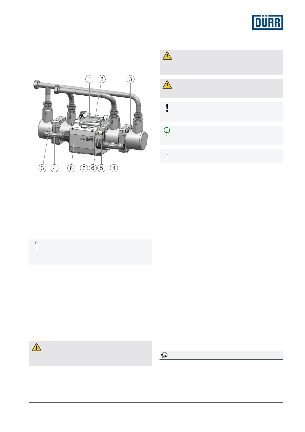
1.1 Overview.................................................. 5
1.2 Short description...................................... 5
2 Safety............................................................... 5
2.1 Presentation of Notes............................... 5
2.2 Intended Use............................................ 5
2.3 Residual risks........................................... 6
2.4 Conduct in the event of a hazardous sit-
uation........................................................ 6
2.5 Staff qualification...................................... 6
2.6 Personal protective equipment................. 7
3 Design and Function...................................... 7
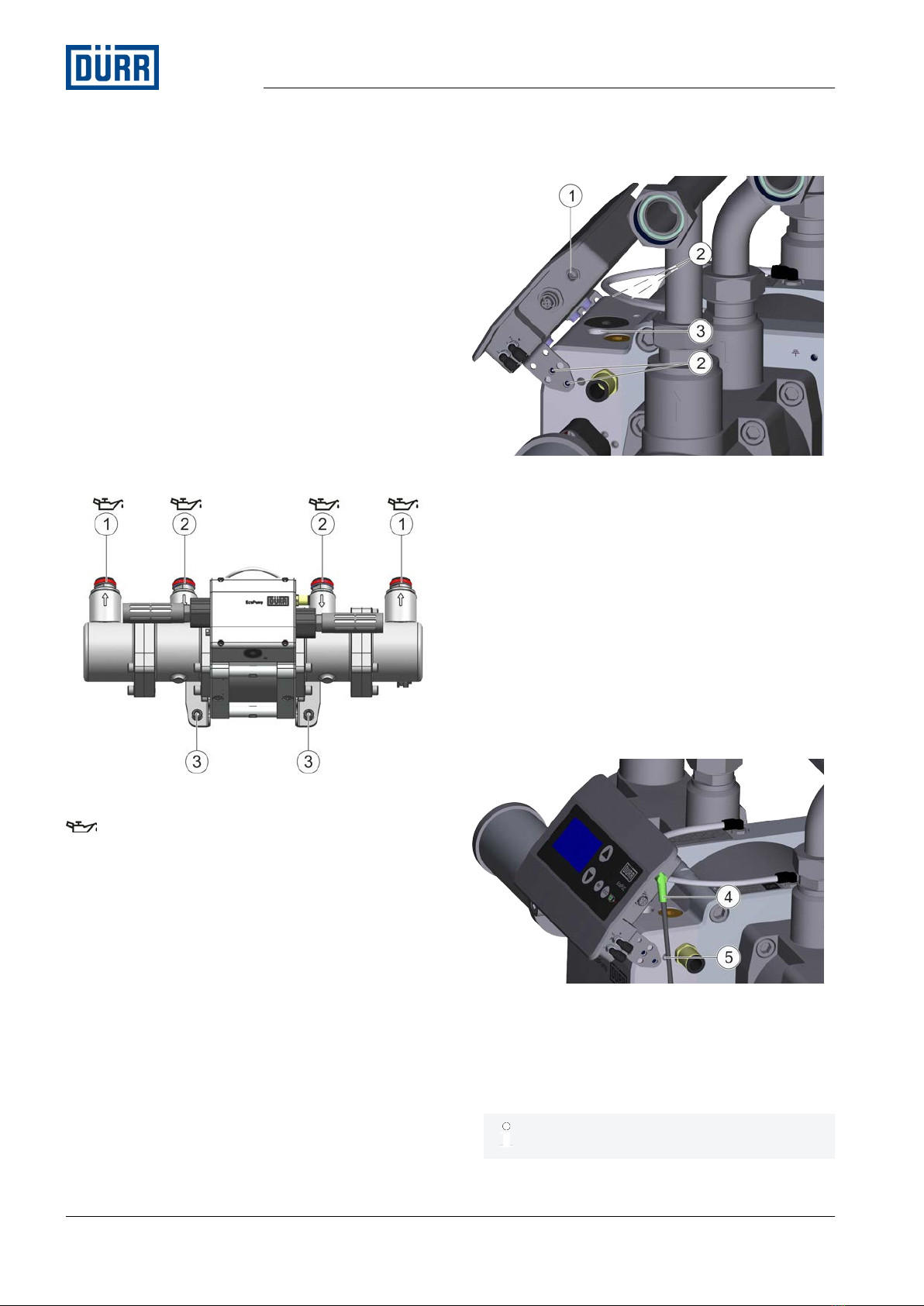
3.1 Control Unit.............................................. 7
3.2 Motor........................................................ 8
3.3 Fluid part.................................................. 8
4 Transport, scope of supply and storage...... 8
4.1 Unpacking................................................ 8
4.2 Transport.................................................. 9
4.3 Scope of delivery...................................... 9
4.4 Handling of packaging material................ 9
4.5 Storage..................................................... 9
5 Assembly......................................................... 9
5.1 Safety recommendations.......................... 9
5.2 Requirements for the Installation point... 10
5.3 Assembly................................................ 10
5.4 Connecting.............................................. 11
6 Commissioning............................................. 11
6.1 Safety recommendations........................ 11
6.2 Commissioning....................................... 12
6.3 Setting operating parameters ................ 13
7 Operation....................................................... 13
7.1 General notes......................................... 13
7.2 Rinsing................................................... 13
7.2.1 Safety recommendations..................... 13
7.2.2 Flush the pump.................................... 13
8 Cleaning........................................................ 14
8.1 Safety recommendations ....................... 14
8.2 Cleaning................................................. 15
9 Maintenance.................................................. 15
9.1 Safety notes........................................... 15
9.2 General notes......................................... 16
9.3 Maintenance schedule........................... 16
9.4 Dismantle and assemble control unit..... 17
9.4.1 Disassemble control unit..................... 17
9.4.2 Remove membrane............................. 17
9.4.3 Removing the valve............................. 18
9.4.4 Install membrane................................. 18
9.4.5 Assembling valve................................ 19
9.4.6 Assemble control unit.......................... 19
9.5 Dismantling and assembling fluid parts.. 20
9.5.1 Disassemble outlet cylinder................. 20
9.5.2 Outlet cylinder assembly..................... 20
9.5.3 Dismantling non-return valve in the
outlet cylinder...................................... 21
9.5.4 Assembling non-return valve in the
outlet cylinder...................................... 21
9.5.5 Dismantle non-return valve in the
piston................................................... 22
9.5.6 Assemble non-return valve in the
piston................................................... 22
9.5.7 Dismantling inlet cylinder..................... 23
9.5.8 Inlet cylinder assembly........................ 23
9.6 Dismantle and assemble motor.............. 24
9.6.1 Dismantle motor.................................. 24
9.6.2 Assemble motor................................... 25
10 Faults............................................................. 26
10.1 Defects table........................................ 26
10.2 Troubleshooting.................................... 28
10.2.1 Replace switchover valve.................. 28
10.2.2 Assembling ice reduction.................. 29
11 Disassembly and Disposal.......................... 33
11.1 Safety recommendations...................... 33
11.2 Disassembly......................................... 34
11.3 Disposal ............................................... 35
12 Technical data............................................... 36
12.1 Dimensions and weight........................ 36
12.2 Connections......................................... 36
12.3 Operating conditions............................ 36
12.4 Emissions............................................. 37
12.5 Operating values.................................. 37
12.6 Compressed air quality......................... 37
12.7 Type plate............................................. 37
12.8 Materials used...................................... 37
12.9 Operating and auxiliary materials......... 37
12.10 Characteristic curve of the outflow
rate....................................................... 38
12.11 Material specification............................ 39
13 Replacement parts, tools and accesso-
ries................................................................. 40
13.1 Replacement parts............................... 40
08/2020 EcoPump HP - MPU00020EN 3/56

13.1.1 Control Unit....................................... 40
13.1.2 Fluid part........................................... 42
13.1.3 Motor................................................. 45
13.1.4 Manifolds........................................... 48
13.1.5 Repair kits......................................... 48
13.1.6 Seal sets............................................ 49
13.2 Tools..................................................... 49
13.3 Accessories.......................................... 49
13.4 Order.................................................... 50
14 Index.............................................................. 51
08/2020EcoPump HP - MPU00020EN4/56

1 Product overview
1.1 Overview
Fig. 1: Assemblies
1 Motor
2 Hose leakage indicator
3 Fluid parts
4 Sound muffler
5 Changeover valve
6 Compressed air connection
7 Control unit valve
8 Control unit
Upon delivery of the pump, the hose for the
leakage indicator is fitted at the top. The hose
for the leakage indicator may alternatively also
be fitted at the bottom of the pump.
1.2 Short description
The horizontal piston pump (hereafter called “Pump”)
with pneumatic drive conveys water-based and sol-
vent-based flammable and non-flammable coating
materials e.g. in automated paint mixing rooms.
2 Safety
2.1 Presentation of Notes
The following notes can appear in this instruction:
DANGER!
High risk situation that can lead to serious injuries or
death.
WARNING!
Medium risk situation that can lead to serious inju-
ries or death.
CAUTION!
Low risk situations that can lead to minor injuries.
NOTICE!
Situations that can lead to material damage.
ENVIRONMENT!
Situations that can lead to environmental damage.
Additional information and recommendations.
2.2 Intended Use
Use
The EcoPump HP is an auto-suction pneumatic hori-
zontal piston pump.
The EcoPump HP may only be used for pumping
water-based and solvent-based flammable and non-
flammable coating materials and their detergents.
The pump is only intended for industrial use.
The pump may only be operated within the approved
technical data Ä 12 “Technical data”.
The pump is approved for use in explosive areas of
Ex zones 1 and 2.
Misuse
If used improperly, it can cause serious injuries.
Examples of wrong use are:
nUse outside a closed process or a remotely con-
trolled and automated process
nInstallation of the pump in an area without forced
ventilation
nUse of unapproved materials, see safety data
sheets
nMaking conversions or changes on your own
nUse of non-conductive fluids Ä 12.11 “Material
specification”
nUse in explosive areas Ex zone 0
nUse of components unapproved by Dürr Systems
Ex labeling
II 2G Ex h IIA T6 Gb X
Product overview
08/2020 EcoPump HP - MPU00020EN 5/56

II - Device group II: all areas except mining
2G - Device category 2 for gaseous atmosphere
Ex h - Mechanical explosion protection
IIA - Explosion group IIA
T6 - Temperature class
Gb - Device protection level Gb
X - The pump is configured for operation in an
ambient temperature of 15°C to 40°C.
2.3 Residual risks
Danger of explosion due to sources of ignition in
an explosive atmosphere.
Sparks, open flames and hot surfaces can cause
explosions in explosive atmospheres. Serious injury
and death could be the consequence.
nBefore carrying out any work, make sure that there
is no explosive atmosphere.
nDo not use any sources of ignition and no open
light in the work area.
nDo not smoke.
nDo not unpack Pump in Ex zone.
nDispose of packaging according to regulation out-
side of Ex zone or store it.
nUse tools with Ex approval.
nGround Pump.
nWear suitable protective equipment.
Sparks due to electrostatic discharge
If the pump is not properly grounded or the potential
equalization fails, components may get charged elec-
trostatically. Electrostatic discharge can cause sparks
that in explosive atmosphere can cause a fire or an
explosion. Serious injury and death could be the con-
sequence.
nGround Pump as specified.
nCheck connection of grounding cable during oper-
ation.
nMeasure volume resistivity.
Escaping material
Material escaping under pressure can cause serious
injuries.
Before working on the product:
nDisconnect the system, in which the product is
installed, from compressed air and material supply.
nDepressurize the lines.
nSecure the system against being switched on
again.
Danger from harmful or irritant substances
Serious injuries or death can result if you come into
contact with dangerous fluids or steam.
nPump Check regularly for leakage. Observe local
regulations and maintenance schedule.
nEnsure that the forced ventilation is operational.
nFollow the safety data sheet.
nWear specified protective equipment.
2.4 Conduct in the event of a hazardous situa-
tion
Conduct in case of danger depends on the operator’s
installation situation.
Perform the following activities:
nClose lines.
nSecure against reconnection.
nDepressurize lines.
2.5 Staff qualification
WARNING!
Inadequate qualification
Wrong estimation of dangers can cause serious
injury or death.
nOnly sufficiently qualified persons may execute
all work.
nSome work requires additional qualification.
Additional qualifications of specialized personnel
are marked with a “+”.
This document is intended for qualified personnel in
industry and craftmanship.
Cleaning staff
The cleaning staff receives regular instructions from
the operator about the following contents:
nUsing the product
nHandling cleaning tools
nHandling cleaning agents
nTechnical Measures for occupational safety and
health
Electrician
Electricians assemble, install, service and repair elec-
trical systems in a professional manner.
Furthermore, electrical engineers have the following
knowledge:
nGuidelines, Standards and Rules of Engineering
nLocal conditions
nElectrical Systems and Their Loading Limits
nTechnical Measures for occupational safety and
health
Safety
08/2020EcoPump HP - MPU00020EN6/56

Mechanic
The mechanic is trained specifically for the field of
work in which he works.
Furthermore, he has the following knowledge:
nGuidelines, Standards and Rules of Engineering
nLocal conditions
nTechnical Measures for occupational safety and
health
The mechanic is responsible for the following activities
on equipment and components:
nAssembly
nWaiting
nMaintenance
nDisassembly
+ Additional qualification high pressure
In addition, the mechanic has knowledge of regula-
tions and safety measures for high pressure systems
> 20 bar.
+ additional qualification explosion protection
In addition to the knowledge of the various specialist
fields, the mechanic has knowledge of regulations and
safety measures when working in potentially explosive
areas.
Dürr Systems offers special product training for
Ä “Hotline and Contact”.
2.6 Personal protective equipment
Wear the required personal protective equipment
when working. Provide the following personal protec-
tive equipment:
Anti-Static Safety Boots
Protect feet from crushing, falling items and
slipping on slippery ground.
Moreover, anti-static safety boots reduce
electrostatic charge by discharging the elec-
trostatic charges.
Eye protection
Protects eyes from dust, paint drops and
particles.
Protective gloves
Protect the hands from:
nmechanical forces
nThermal forces
nChemical effects
Protective workwear
Tight fitting workwear with low tear strength,
tight sleeves and no hanging parts.
Respirator mask
Protects from hazardous gases, vapors, dust
and similar materials and media.
Use ear protection
Protects from auditory damage due to noise.
3 Design and Function
3.1 Control Unit
Fig. 2: Control Unit operation
1 Motor
2 Sound muffler
3 Compressed air connection
4 Valve
5 Distributor block
Air reaches into the distributor block of the control unit
(5) via the compressed air connection (3). The valve
(4) in the distributor block (5) controls the air intake to
the motor (1). The air outlet is through the two sound
mufflers (2).
Design and Function
08/2020 EcoPump HP - MPU00020EN 7/56

3.2 Motor
Fig. 3: Motor operation
1 Cylinder
2 Piston
The pneumatically operated motor drives the pump.
The piston (2) of the pneumatic motor divides the cyl-
inder (1) into two air chambers. Compressed air
moves the piston (2) back and forth in the cylinder (1).
When the piston (2) reaches one end of the cylinder
(1), the piston switches the switch valve. The switch
valve causes the control unit to change the supply of
engine air from one side of the piston (2) to the other.
The piston (2) then moves in the opposite direction.
3.3 Fluid part
Fig. 4: Fluid part operation
1 Suction line
2 Pressure line
3 Non-return valve in the outlet cylinder
4 Non-return valve in the piston
5 Piston rod
The motor and the fluid parts are mutually linked
through the piston rod (5). The movement of the
piston rod causes suction of the material into a fluid
part through the suction line (1). At the same time,
material is pushed out through the pressure line (2) in
the second Fluid part. Non-return valves (3) and (4)
prevent material from flowing back.
4 Transport, scope of supply and
storage
4.1 Unpacking
DANGER!
Electrostatically charged plastic films and foils
in potentially explosive areas
The foil and the product can charge electrostatically
at the time of the unpacking. Electrostatic discharge
can cause sparks that in explosive atmosphere can
cause a fire or an explosion. Serious injury and
death could be the consequence.
nUnpack product outside Ex zones.
nDischarge the product.
nDispose packaging outside of the Ex zone in
accordance with the regulation or store properly
for a later return.
Transport, scope of supply and storage
08/2020EcoPump HP - MPU00020EN8/56

4.2 Transport
WARNING!
Lifting heavy loads
Lifting heavy loads could cause back injuries,
crushing or compression. Serious injuries can be the
consequence.
nLift heavy loads only by using suitable hoists.
NOTICE!
Incorrect Transport
Incorrect Transport can cause property damage.
nProtect Pump from moisture.
nProtect Pump from vibrations.
nTransport temperature: -30°C to 60°C
Fig. 5: Attaching the round slings
Requirements:
nPump has been disassembled Ä 11.2 “Disas-
sembly”.
1. Place one round sling each around the fluid parts
(1).
ðSee that the round slings cannot slip.
2. Transport pump using a crane.
4.3 Scope of delivery
The scope of supply only includes the pump.
Personnel:
nMechanic
Protective equipment:
nProtective gloves
nProtective workwear
nAnti-Static Safety Boots
1. Check the pump for integrity on receiving it.
2. Report defects immediately Ä “Hotline and Con-
tact”.
4.4 Handling of packaging material
ENVIRONMENT!
Incorrect disposal
Incorrectly disposed packaging material can
damage environment.
nDispose of material no longer required in an
environment-friendly manner.
nObserve local disposal specifications.
4.5 Storage
Requirements for the warehouse:
nDo not store outdoors.
nStore in a dry and dust-free place.
nDo not expose to aggressive media.
nProtect from solar radiation.
nAvoid mechanical vibrations.
nClose all openings when storing after disassembly.
nTemperature: 10°C to 40°C
nRelative humidity: 35% to 90%
5 Assembly
5.1 Safety recommendations
WARNING!
Unsuitable tools in explosive areas
Tools that do not have Ex approval can generate
sparks and cause a fire or an explosion in Ex zones.
It can cause serious injuries or death.
nIf possible, carry out cleaning and maintenance
work outside the Ex zones.
nFor work within the Ex zone, use tools with the
corresponding Ex labeling.
WARNING!
Lifting heavy loads
Lifting heavy loads could cause back injuries,
crushing or compression. Serious injuries can be the
consequence.
nLift heavy loads only by using suitable hoists.
Assembly
08/2020 EcoPump HP - MPU00020EN 9/56

5.2 Requirements for the Installation point.
nIt should be possible to disconnect the control air
supply and the material feed and prevent them
from reconnecting.
nLines, seals and screw connections must be
designed to conform to the pump requirements
Ä 12.5 “Operating values”.
nThe workplace must have a ventilation.
nThe pump must be protected from atmospheric
influences at the installation point.
nThe pump is finally connected to the interface (e.g.
pipeline). Any docking is not permitted.
nThe maintenance unit for supplying the pump with
air must be equipped with an overpressure valve
that triggers at 6bar drive air pressure.
5.3 Assembly
Assembling the pump
Fig. 6: Assemble pump
Molykote TP-42 Paste
1 Pressure line connection
2 Suction line connection
3 Support bracket
Personnel:
nMechanic
n + additional qualification explosion protection
Protective equipment:
nProtective gloves
nAnti-Static Safety Boots
1. Mount pump using support brackets (3) on the wall
or a fixture designed for the pump. Mount pump
such that connections (1) and (2) point upwards.
Assemble EcoPUC A (optional)
Fig. 7: Assemble EcoPUC A
1 Sensor connection
2 Screws
3 Opening for sensor
Personnel:
nMechanic
Protective equipment:
nProtective gloves
nAnti-Static Safety Boots
1. Screw EcoPUC A with four screws (2) below on
the control unit of the pump and tighten.
2. Connect sensor to EcoPUC A.
Fig. 8: Assemble sensor
3. Push sensor with insertion nipple (4) into the
opening (3) of the control unit.
4. Secure insertion nipple (4) using the threaded pin
(5).
The threaded pin is included in the scope of
supply of EcoPUC A.
Assembly
08/2020EcoPump HP - MPU00020EN10/56

5.4 Connecting
Connect material supply
Personnel:
nMechanic
n + additional qualification explosion protection
Protective equipment:
nProtective workwear
nProtective gloves
nAnti-Static Safety Boots
1. Unscrew the protective caps from the manifolds.
2. Grease all O-rings and threads of the pipelines.
3. Screw the tube from material feed into the suction
pipe manifold Ä 5.3 “Assembly”.
4. Screw the tube from material discharge into the
pressure pipe manifold Ä 5.3 “Assembly”.
Connect compressed air
Fig. 9: Connect compressed air
Personnel:
nMechanic
n + additional qualification explosion protection
Protective equipment:
nProtective workwear
nProtective gloves
nAnti-Static Safety Boots
1. Connect the compressed air hose to the connec-
tion (1).
Grounding the Pump
Movement of the piston and of the flowing material
create the charge. The charge can only flow if the
piston pump is grounded with all components. Con-
nection of the suction pipe and pressure pipe are not
sufficient for grounding.
The grounding holes are on both sides of the drive.
The grounding holes are diagonally opposite.
Fig. 10: Grounding the Pump
Personnel:
nElectrician
n + additional qualification explosion protection
Protective equipment:
nProtective workwear
nAnti-Static Safety Boots
1. Connect the grounding cable to one of the two
grounding bores.
6 Commissioning
6.1 Safety recommendations
WARNING!
Risk of injury due to noise
The sound pressure level during commissioning
may cause severe hearing damage.
nWear ear protection.
nPut the pump only with assembled sound muffler
into operation.
Commissioning
08/2020 EcoPump HP - MPU00020EN 11/56

WARNING!
Risk of injury due to escaping material
Escaping material under pressure can cause serious
injuries.
Before commissioning the pump:
nEnsure that the pump is assembled as specified.
nEnsure that all screw connections are tightened
according to the specifications of the operation
manual. Tightening torque of screws used to
tighten the housing parts: 50Nm.
nConsider using a safety valve or another system
suitable to prevent overpressure to ensure that
the hydrostatic pressure in the pump does not
exceed 24.5bar. Stop category 0 and PLr = b
WARNING!
Danger from harmful or irritant substances
Serious injuries or death can result if you come into
contact with dangerous fluids or steam.
nPump Check regularly for leakage. Observe local
regulations and maintenance schedule.
nEnsure that the forced ventilation is operational.
nFollow the safety data sheet.
nWear specified protective clothing.
nAvoid contact (e.g. with eyes, skin).
WARNING!
Danger due to escaping compressed air
Compressed air escaping from the sound muffler
can contain solid or liquid particles. Particles under
pressure can injure the eyes or the skin.
nWear specified protective equipment.
WARNING!
Unsuitable tools in explosive areas
Tools that do not have Ex approval can generate
sparks and cause a fire or an explosion in Ex zones.
It can cause serious injuries or death.
nIf possible, carry out cleaning and maintenance
work outside the Ex zones.
nFor work within the Ex zone, use tools with the
corresponding Ex labeling.
The operator must ensure that connected pipe-
lines or hose lines are tested according to the
specifications in force (e.g. pressure test).
6.2 Commissioning
Checks Before Commissioning
nPump is grounded.
nThe pump is properly assembled Ä 5 “Assembly”.
nThe maintenance unit for supplying the pump with
air is equipped with an overpressure valve that trig-
gers at 6bar drive air pressure.
Put pump into operation
Personnel:
nMechanic
n + additional qualification explosion protection
Protective equipment:
nProtective workwear
nProtective gloves
nEye protection
nUse ear protection
nAnti-Static Safety Boots
1. Purge pump before the initial commissioning Ä 7.2
“Rinsing”.
Residues of the testing media might still be
in the pump.
2. NOTICE!
Hardening material
If the pump is used to convey hardener compo-
nents, the hardener component may harden
inside of the pump due to getting in contact with
air and damage the pump.
nBleed pump.
Bleed pump.
nLet the pump run with the minimum cycle rate.
3. During this time, check the tightness of the pump,
connections and lines.
4. Watch out for unusual noises. Carry out checks if
there are unusual noises Ä 7.1 “General notes”.
Commissioning
08/2020EcoPump HP - MPU00020EN12/56

6.3 Setting operating parameters
Personnel:
nMechanic
n + additional qualification explosion protection
n + Additional qualification high pressure
Protective equipment:
nProtective workwear
nUse ear protection
nProtective gloves
nAnti-Static Safety Boots
1. Set the operating parameters on the higher level
control.
2. Check operating parameters Ä 12.5 “Operating
values”.
7 Operation
7.1 General notes
Personnel:
nMechanic
n + additional qualification explosion protection
Protective equipment:
nEye protection
nUse ear protection
nProtective gloves
nProtective workwear
nAnti-Static Safety Boots
Check for unusual noises during operation. Perform
visual inspections:
nCheck tightness of the connections.
nIf there are conspicuous noises, carry out further
checks during down times.
nCheck for steady delivery pressure.
nThe maintenance unit for supplying the pump with
air is equipped with an overpressure valve that trig-
gers at 6bar connection air pressure.
If the pump is not in operating mode, the
number of cycle of the pump can drop down to
the minimum flow velocity of the medium.
nThis reduces pump wear and operating
costs.
7.2 Rinsing
7.2.1 Safety recommendations
NOTICE!
Material damage due to unsuitable rinsing agent
If the rinsing agent reacts chemically with the com-
ponents or the material, components get damaged.
nUse only the rinsing agents that are compatible
with the components and the material.
nRefer to safety data sheet of material manufac-
turer.
7.2.2 Flush the pump
Personnel:
nMechanic
n + additional qualification explosion protection
Protective equipment:
nEye protection
nProtective gloves
nProtective workwear
nRespirator mask
nAnti-Static Safety Boots
Complete the following steps if the pump is not in
operation for a longish period:
nPurge pump with a suitable detergent Ä 12.9
“Operating and auxiliary materials”.
nDisconnect compressed air supply to pump.
Operation
08/2020 EcoPump HP - MPU00020EN 13/56

8 Cleaning
8.1 Safety recommendations
WARNING!
Danger of fire and explosion
Flammable coating materials and their detergents
and cleaning agents can cause a fire or an explo-
sion.
nEnsure that the flashpoint of the cleaning agent
is at least 15K above the ambient temperature or
clean Pump at the cleaning areas with active
technical ventilation, in painting booths,
according to EN 16985.
nOnly electrically conductive containers may be
used for the cleaning fluid. Containers must be
grounded.
nNote explosion group of the fluid.
nFollow the safety data sheet.
nEnsure that forced ventilation and fire protection
equipment are in operation.
nDo not use sources of ignition and open light.
nDo not smoke.
nGround Pump.
WARNING!
Unexpected motor start
If the pump is connected to the compressed air
supply, the motor may start unexpectedly. This may
cause a crushing hazard an injuries due to parts
flying around.
Before working on the product:
nDisconnect the system, in which the product is
installed, from compressed air and material
supply.
nSecure the system against being switched on
again.
nDepressurize the lines.
nEnsure that the pump is unpressurized.
nInstall appropriate pressure release device, e.g.
valve or ball valve, to ensure safe depressuriza-
tion.
WARNING!
Danger from harmful or irritant substances
Serious injuries or death can result if you come into
contact with dangerous fluids or steam.
nPump Check regularly for leakage. Observe local
regulations and maintenance schedule.
nEnsure that the forced ventilation is operational.
nFollow the safety data sheet.
nWear specified protective clothing.
nAvoid contact (e.g. with eyes, skin).
WARNING!
Risk of injury due to escaping material
Escaping compressed material can cause serious
injury.
Before working on the product:
nDisconnect the system with the product from
power supply and material supply.
nSecure the system against being switched on
again.
nDepressurize the lines.
NOTICE!
Unsuitable cleaning agents
Unsuitable detergents can cause material damage.
nOnly use cleaning agents approved by the mate-
rial manufacturer.
nFollow safety data sheets.
nUse alcohols (isopropanol, n-butanol) for non-flam-
mable coating materials.
nRemove dried paint residue with a thinner
approved by the paint manufacturer.
NOTICE!
Unsuitable Cleaning Tools
Unsuitable cleaning tools can cause damage.
nOnly use cloths, soft brushes and paintbrushes.
nDo not use abrasive cleaning tools.
nDo not use compressed air for cleaning.
nDo not use any thinner spray guns.
nDo not use high pressure for cleaning agents.
Cleaning
08/2020EcoPump HP - MPU00020EN14/56

8.2 Cleaning
ENVIRONMENT!
Improper waste disposal
Improper waste disposal threatens the environment
and prevents re-use and recycling.
nClean components before their disposal.
nAlways dispose of components in accordance
with their characteristics.
Ä 12.8 “Materials used”
nCollect leaked out utilities and auxiliaries com-
pletely.
nDispose of work equipment soaked in coating
materials or operating substances according to
the disposal provisions in force.
nDispose of utilities and auxiliaries according to
the disposal provisions in force.
nIn case of doubt, refer to the local disposal
authorities.
Make sure that the Pump is completely free of media
residues and other contamination.
Personnel:
nCleaning staff
Protective equipment:
nProtective gloves
nAnti-Static Safety Boots
nProtective workwear
nEye protection
nRespirator mask
1. Clean pump carefully using a moist cloth.
9 Maintenance
9.1 Safety notes
WARNING!
Unsuitable tools in explosive areas
Tools that do not have Ex approval can generate
sparks and cause a fire or an explosion in Ex zones.
It can cause serious injuries or death.
nIf possible, carry out cleaning and maintenance
work outside the Ex zones.
nFor work within the Ex zone, use tools with the
corresponding Ex labeling.
WARNING!
Unsuitable replacement parts in explosive areas
Replacement parts not compliant with the specifica-
tions of the ATEX guidelines can cause explosions
in an explosive atmosphere. Serious injury and
death could be the consequence.
nUse exclusively original replacement parts.
WARNING!
Unexpected motor start
If the pump is connected to the compressed air
supply, the motor may start unexpectedly. This may
cause a crushing hazard an injuries due to parts
flying around.
Before working on the product:
nDisconnect the system, in which the product is
installed, from compressed air and material
supply.
nSecure the system against being switched on
again.
nDepressurize the lines.
nEnsure that the pump is unpressurized.
nInstall appropriate pressure release device, e.g.
valve or ball valve, to ensure safe depressuriza-
tion.
WARNING!
Danger from harmful or irritant substances
Serious injuries or death can result if you come into
contact with dangerous fluids or steam.
nPump Check regularly for leakage. Observe local
regulations and maintenance schedule.
nEnsure that the forced ventilation is operational.
nFollow the safety data sheet.
nWear specified protective clothing.
nAvoid contact (e.g. with eyes, skin).
WARNING!
Risk of injury due to escaping material
Escaping compressed material can cause serious
injury.
Before working on the product:
nDisconnect the system with the product from
power supply and material supply.
nSecure the system against being switched on
again.
nDepressurize the lines.
Maintenance
08/2020 EcoPump HP - MPU00020EN 15/56

9.2 General notes
Maintenance work on the pump may only be carried
out by personnel with the qualifications and protective
equipment listed below.
Personnel:
nMechanic
n + additional qualification explosion protection
Protective equipment:
nProtective workwear
nRespirator mask
nEye protection
nProtective gloves
nAnti-Static Safety Boots
9.3 Maintenance schedule
If a maintenance assistant is used in the system visualizer, the maintenance intervals of the maintenance
assistant are valid.
The life cycle and the associated maintenance intervals depend heavily on the abrasiveness and temper-
ature of the material to be pumped as well as the pumping pressure and the number of dual strokes of
the pump. The present details are guide values and must be suitably adjusted according to the applica-
tion.
Interval Maintenance work
weekly Check cleanliness of the pump.
Check tightness and state of the pump.
Test the seal tightness and condition of the connections and
lines.
Check noise generation in the pump.
Check for steady delivery pressure.
nÄ 10.1 “Defects table”
after 10 million cycles (corresponds to 20
dual strokes/min, for about 1 year)
Replace bellows Ä 9.5.7 “Dismantling inlet cylinder”.
Replace rod seal of the air motor Ä 9.5.7 “Dismantling inlet cyl-
inder”.
Replace piston seal of the air motor Ä 9.6.1 “Dismantle motor”.
Replace piston seal of the fluid part Ä 9.5.7 “Dismantling inlet
cylinder”.
Replace piston guide belt Ä 9.5.7 “Dismantling inlet cylinder”.
Replace changeover valve Ä 10.2.1 “Replace switchover
valve”.
Replace valve in the control unit. Ä 9.4.3 “Removing the valve”
every 5 years Replace non-return valves Ä 9.5.3 “Dismantling non-return
valve in the outlet cylinder”, Ä 9.5.5 “Dismantle non-return
valve in the piston”.
Maintenance
08/2020EcoPump HP - MPU00020EN16/56

9.4 Dismantle and assemble control unit
9.4.1 Disassemble control unit
Fig. 11: Disassemble control unit
Personnel:
nMechanic
n + additional qualification explosion protection
n + Additional qualification high pressure
Protective equipment:
nProtective workwear
nRespirator mask
nEye protection
nProtective gloves
nAnti-Static Safety Boots
1. Thread off four screws (1).
2. Remove control unit (2) from the motor.
3. Remove O-rings between control unit and motor.
9.4.2 Remove membrane
Fig. 12: Remove membrane
Personnel:
nMechanic
n + additional qualification explosion protection
n + Additional qualification high pressure
Protective equipment:
nProtective workwear
nRespirator mask
nEye protection
nProtective gloves
nAnti-Static Safety Boots
1. Unscrew sound muffler (4).
2. Thread off two screws (3).
3. Pull out adapter (5) together with O-ring from the
housing (1).
4. Pull out membrane (2) from the housing (1) using a
long nose pliers.
Maintenance
08/2020 EcoPump HP - MPU00020EN 17/56

9.4.3 Removing the valve
Fig. 13: Removing the valve
Personnel:
nMechanic
n + additional qualification explosion protection
n + Additional qualification high pressure
Protective equipment:
nProtective workwear
nRespirator mask
nEye protection
nProtective gloves
nAnti-Static Safety Boots
1. Unscrew sealing screw (1) with O-ring on both
sides of the distributor block.
2. Remove spacers (2) on both sides of the distrib-
utor block.
3. Push out valve (3) from the distributor block using
suitable tool (e.g. W02850031).
4. Check whether the piston can easily move in the
valve (3).
ðIf the piston works properly and the control unit
is leaking, the O-rings on the valve could be
damaged.
5. Check O-rings on the valve for damage.
ðReplace damaged O-rings.
9.4.4 Install membrane.
Fig. 14: Install membrane
Klüber Syntheso GLEP 1
Molykote TP-42 Paste
N24160008, N24160009: 6Nm
N24160010: 16Nm
Personnel:
nMechanic
n + additional qualification explosion protection
n + Additional qualification high pressure
Protective equipment:
nProtective workwear
nRespirator mask
nEye protection
nProtective gloves
nAnti-Static Safety Boots
1. Lightly grease bore for the membrane (2).
2. Push in membrane (2) into the housing (1) up to
the stop with the closed side in front.
3. Push in adapter (5) with O-ring into the housing
(1).
4. Grease screws (3).
5. Tighten adapter (5) with two screws (3).
ðRespect tightening torque.
6. Screw-in and hand-tighten sound mufflers (4) in
the adapter (5).
Maintenance
08/2020EcoPump HP - MPU00020EN18/56

9.4.5 Assembling valve
Fig. 15: Installing Valve
Klüber Syntheso GLEP 1
Loctite 222
6Nm
Personnel:
nMechanic
n + additional qualification explosion protection
n + Additional qualification high pressure
Protective equipment:
nProtective workwear
nRespirator mask
nEye protection
nProtective gloves
nAnti-Static Safety Boots
Piston and sleeve of the valve (3) are paired.
Do not replace with other valves.
1. Apply Loctite to the thread of the screw plug (5).
2. Screw sealing screw (5) with washer (4) into the
housing.
ðObserve tightening torque.
3. Grease valve (3).
4. Carefully push the valve (3) into the distributor
block using a suitable tool (e.g. W02850031).
5. Place spacer (2) on the valve.
6. Apply Loctite on the threads of the sealing screw
(1).
7. Screw sealing screw (1) into the distributor block.
ðObserve tightening torque.
9.4.6 Assemble control unit
Fig. 16: Assemble control unit
Molykote TP-42 Paste
N24160008, N24160009: 6Nm
N24160010: 16Nm
Personnel:
nMechanic
n + additional qualification explosion protection
n + Additional qualification high pressure
Protective equipment:
nProtective workwear
nRespirator mask
nEye protection
nProtective gloves
nAnti-Static Safety Boots
1. Grease O-rings.
2. Insert O-rings between control unit and motor.
3. Grease screws (1).
4. Firmly attach control unit (2) with four screws (1).
ðRespect tightening torque.
Maintenance
08/2020 EcoPump HP - MPU00020EN 19/56

9.5 Dismantling and assembling fluid parts
9.5.1 Disassemble outlet cylinder
NOTICE!
Hardening material
If the pump is used to convey hardener compo-
nents, residues of the hardener component may
harden inside of the pump due to getting in contact
with air and damage the pump.
nPurge pump thoroughly prior to conducting main-
tenance work or disassembly.
nClean components in contact with material thor-
oughly.
Use with hardener components
If the pump is used to convey hardener compo-
nents, replace the bellows as soon as the bel-
lows is in contact with air Ä 9.5.7 “Dismantling
inlet cylinder”.
Fig. 17: Disassemble outlet cylinder.
Personnel:
nMechanic
n + additional qualification explosion protection
Protective equipment:
nProtective gloves
nProtective workwear
nAnti-Static Safety Boots
1. Remove four screws (1).
2. Pull out housing (2) carefully from the piston (3).
9.5.2 Outlet cylinder assembly
Fig. 18: Outlet cylinder assembly
Molykote TP-42 Paste
N24160008: 1. Stage 12 Nm, 2. Stage 35 Nm
N24160009, N24160010: 1. Stage 25 Nm, 2.
Stage 50Nm
Personnel:
nMechanic
n + additional qualification explosion protection
Protective equipment:
nProtective gloves
nProtective workwear
nAnti-Static Safety Boots
1. Push the housing (2) onto the piston (3).
2. Tighten four screws (1). Respect tightening torque.
Maintenance
08/2020EcoPump HP - MPU00020EN20/56
This manual suits for next models
9
Table of contents
Other DÖRR Water Pump manuals
Popular Water Pump manuals by other brands

Stuart Turner
Stuart Turner PH 35 ES Installation, operation & maintenance instructions

SFA
SFA Sanipro XR installation instructions

Dover
Dover PSG WILDEN HS430S manual

ITT
ITT Goulds Pumps 3755 Installation, operation and maintenance manual

SymCom
SymCom PumpSaver Plus 235P installation instructions

salmson
salmson IMMERSON S Installation and starting instructions

Pfeiffer Vacuum
Pfeiffer Vacuum HiPace 700 operating instructions

Sealey
Sealey WPD235A.V2 manual

KNF
KNF NF5 Operating and installation instructions

Binks
Binks HP 4/20 Product instructions

Northern Industrial Tools
Northern Industrial Tools 1/2 HP SUMP PUMP owner's manual

Enerpac
Enerpac XC Series instruction sheet