DAB e.sybox Series User manual

ENGLISH
GB
57
INDEX
Key 60
Warnings 60
Responsibility 61
1. General 61
1.1 Description of the Integrated Inverter 62
1.2 Integrated expansion vessel 62
1.3 Integrated electropump 63
1.4 Technical characteristics 64
2. Installation 65
2.1 Vertical Conguration 66
2.1.1 Hydraulic connections 66
2.1.2 Loading operation – Installation above head and below head 67
2.2 Horizontal conguration 67
2.2.1 Hydraulic connections 68
2.2.2 Orientation of the interface panel 68
2.2.3 Loading operation – Installation above head and below head 69
3. Commissioning 69
3.1 Electrical connections 69
3.2 Conguration of the integrated inverter 70
3.3 Priming 70
4. Protection systems 71
4.1 Description of blockages 71
4.1.1 “BL” AAnti Dry-Run (Protection against dry running) 71
4.1.2 Anti-Cycling (Protection against continuous cycles without utility request) 72
4.1.3 Anti-Freeze (Protection against freezing of water in the system) 72
4.1.4 “BP1” Blockage due to fault of the internal pressure sensor 72
4.1.5 PB” Blockage due to line voltage outside specications 72
4.1.6 “SC” Blockage due to short circuit between the motor phases 72
4.2 Manual reset of error conditions 73
4.3 Self-reset of error conditions 73
5. Inverter electronic control and user interface 73
5.1 Operation with control unit 73
5.1.1 Functions made available by control units 74
5.1.2 Electrical connections of utility inputs and outputs 74
5.1.3 Safety mode operation 74
5.1.4 Control unit function setup 75
5.1.5 Association and disassociation of e.sybox and control unit 75
6. The keypad and the display 76
6.1 Direct access with a combination of keys 77
6.2 Access by name with a drop-down menu 80
6.3 Structure of the menu pages 81
6.4 Blocking parameter setting by Password 82
6.5 Enabling and disabling the motor 82
7. Meaning of the individual parameters 82
7.1 User Menu 82
7.1.1 Status 82
7.1.2 RS: Rotation speed display 82
7.1.3 VP: Pressure display 82
7.1.4 VF: Flow display 82
7.1.5 PO: Absorbed power display 83
7.1.6 C1: Phase current display 83
7.1.7 Operating hours and number of starts 83
7.1.8 PI: Power histogram 83
7.1.9 Multi-pump system 83
7.1.10 Output ow meter 83
7.1.11 VE: Version display 83
7.1.12 FF: Fault log display 84
7.2 Monitor Menu 84
7.2.1 CT: Display contrast 84
7.2.2 BK: Display brightness 84
7.2.3 TK: Backlight switch-on time 84
7.2.4 LA: Language 84
7.2.5 TE: Dissipator temperature display 84
7.3 Setpoint Menu 84
7.3.1 SP: Setting the setpoint pressure 84
7.3.2 Setting the auxiliary pressures 84
7.3.2.1 P1: Setting the auxiliary setpoint 1 85
7.3.2.2 P2: Setting the auxiliary setpoint 2 85
7.3.2.3 P3: Setting the auxiliary setpoint 3 85
7.3.2.4 P4: Setting the auxiliary setpoint 4 85
7.4 Manual Menu 85
7.4.1 Status 85
7.4.2 RI: Speed setting 85
7.4.3 VP: Pressure display 86
7.4.4 VF: Flow display 86
7.4.5 PO: Absorbed power display 86
7.4.6 C1: Phase current display 86
7.4.7 RS: Rotation speed display 86
7.4.8 TE: Dissipator temperature display 86
7.5 Installer Menu 86
7.5.1 RP: Setting the pressure fall to restart 86
7.5.2 OD: Type of plant 86
7.5.3 AD: Address conguration 86

ENGLISH
58
GB
7.5.4 MS: Measuring system 87
7.5.5 AS: Association of devices 87
7.5.6 PR: Remote pressure sensor 88
7.6 Technical Assistance Menu 88
7.6.1 TB: Water lack blockage time 88
7.6.2 T1: Switch-o time after low pressure signal 89
7.6.3 T2: Delay in switching o 89
7.6.4 GP: Proportional gain coecient 89
7.6.5 GI: Integral gain coecient 89
7.6.6 RM: Maximum speed 89
7.6.7 Setting the number of devices and of reserves 89
7.6.8 NA: Active devices 89
7.6.9 NC: Simultaneous devices 89
7.6.10 IC: Conguration of the reserve 89
7.6.10.1 Examples of conguration for multipump systems 90
7.6.11 ET: Max. switching time 90
7.6.12 AY: Anti Cycling 91
7.6.13 AE: Enabling the anti-block function 91
7.6.14 AF: Enabling the anti-freeze function 91
7.6.15 Setup of the auxiliary digitali inputs IN1, IN2, IN3, IN4 91
7.6.15.1 Disabling the functions associated with the input 92
7.6.15.2 Setting external oat function 92
7.6.15.3 Setting auxiliary setpoint input function 92
7.6.15.4 Setting system enabling and fault reset 93
7.6.15.5 Setting low pressure detection (KIWA) 94
7.6.16 Setup of the outputs OUT1, OUT2 94
7.6.17 O1: Setting output 1 function 95
7.6.18 O2: Setting output 2 function 95
7.6.19 FW: Firmware update 95
7.6.20 RF: Fault and warning reset 95
7.6.21 PW: Change password 95
7.6.21.1 Password for multipump systems 96
8. Reset and factory settings 96
8.1 Reset generale del sistema 96
8.2 Factory settings 96
8.3 Restoring the factory settings 96
9. Particular installations 98
9.1 Inhibiting self-priming 98
9.2 Wall installation 99
9.3 Installation with Quick Connection 99
9.4 Multiple Sets 99
9.4.1 Introduction to multipump systems 99
9.4.2 Making a multipump system 99
9.4.3 Wireless communication 100
9.4.4 Connection and setting of the inputs 100
9.4.5 Parameters linked to multipump operation 100
9.4.6 First start of the multipump system 101
9.4.7 Multipump adjustment 101
9.4.8 Assigning the starting order 102
9.4.9 Max. switching time 102
9.4.10 Reaching the maximum inactivity time 102
9.4.11 Reserves and number of devices that participate in pumping 102
9.4.12 Wireless Control 103
10. Maintenance 103
10.1 Accessory tool 103
10.2 Emptying the system 105
10.3 Non-return valve 105
10.4 Motor shaft 106
10.5 Expansion Vessel 106
11. Updang the e.Sybox rmware 106
11.1 General 106
11.2 Updating the rmware 107
11.2.1 Updating between one e.sybox and another 107
11.2.1.1 Manual updating 107
11.2.1.2 Automatic updating 107
11.2.1.3 Semiautomatic updating 108
11.2.2 Updating the e.sybox by e.sylink 108
12. Troubleshooting 108
13. Disposal 110
14. Guarantee 110


ENGLISH
60
GB
and working conditions, have been approved by the person in and working conditions, have been approved by the person in
charge of plant safety, authorizing them to perform all the neces-charge of plant safety, authorizing them to perform all the neces-
sary activities, during which they are able to recognize and avoid sary activities, during which they are able to recognize and avoid
all dangers. (Denition for technical personnel IEC 364).all dangers. (Denition for technical personnel IEC 364).
The products dealt with in this discussion fall within the type of The products dealt with in this discussion fall within the type of
professional equipment and belong to insulation class 1.professional equipment and belong to insulation class 1.
ItIt is the responsibility of the installer to make sure that the power is the responsibility of the installer to make sure that the power
supply system is equipped with an ecient grounding system supply system is equipped with an ecient grounding system
according to the regulations in force.according to the regulations in force.
To improve immunity to possible noise radiating to other To improve immunity to possible noise radiating to other
equipment, it is advisable to use separate wiring to power the equipment, it is advisable to use separate wiring to power the
inverter.inverter.
The appliance is not intended to be used by persons (including The appliance is not intended to be used by persons (including
children) with reduced physical, sensory or mental capacities, or children) with reduced physical, sensory or mental capacities, or
who lack experience or knowledge, unless, through the media-who lack experience or knowledge, unless, through the media-
tion of a person responsible for their safety, they have had the tion of a person responsible for their safety, they have had the
benet of supervision or of instructions on the use of the appli-benet of supervision or of instructions on the use of the appli-
ance. Children must be supervised to ensure that they do not ance. Children must be supervised to ensure that they do not
play with the appliance. play with the appliance.
SafetySafety
Use is allowed only if the electric system is in possession of safe-Use is allowed only if the electric system is in possession of safe-
ty precautions in accordance with the regulations in force in the ty precautions in accordance with the regulations in force in the
country where the product is installed (for Italy CEI 64/2).country where the product is installed (for Italy CEI 64/2).
Pumped liquidsPumped liquids
The machine has been designed and made for pumping water, The machine has been designed and made for pumping water,
free from explosive substances and solid particles or bres, with free from explosive substances and solid particles or bres, with
a density of 1000 Kg/m³, a kinematic viscosity of 1mm²/s and a density of 1000 Kg/m³, a kinematic viscosity of 1mm²/s and
non chemically aggressive liquids.non chemically aggressive liquids.
The power supply cable must never be used to carry or shift the The power supply cable must never be used to carry or shift the
pump.pump.
KEY KEY
The following symbols have been used in the discussion:The following symbols have been used in the discussion:
Situation of general danger. Failure to respect the instruc-
tions that follow may cause harm to persons and property.
Situation of electric shock hazard. Failure to respect the
instructions that follow may cause a situation of grave risk for
personal safety.
Notes
WARNINGSWARNINGS
This manual refers to e.sybox products. In the following discussion, the This manual refers to e.sybox products. In the following discussion, the
term e.sybox will be used when the characteristics are shared by both term e.sybox will be used when the characteristics are shared by both
models. If the characteristics dier, the models and their dierences will models. If the characteristics dier, the models and their dierences will
be specied.be specied.
RRead this documentation carefully before installation. ead this documentation carefully before installation.
Installation and operation must comply with the local safety reg-Installation and operation must comply with the local safety reg-
ulations in force in the country in which the product is installed. ulations in force in the country in which the product is installed.
Everything must be done in a workmanlike manner.Everything must be done in a workmanlike manner.
Failure to respect the safety regulations not only causes risk to Failure to respect the safety regulations not only causes risk to
personal safety and damage to the equipment, but invalidates personal safety and damage to the equipment, but invalidates
every right to assistance under guarantee.every right to assistance under guarantee.
Skilled personnelSkilled personnel
TThe electrical and hydraulic connections may only be carried out he electrical and hydraulic connections may only be carried out
by skilled personnel in possession of the technical qualications by skilled personnel in possession of the technical qualications
required by the safety regulations in force in the country in which required by the safety regulations in force in the country in which
the product is installed.the product is installed.
The term skilled personnel means persons whose training, ex-The term skilled personnel means persons whose training, ex-
perience and instruction, as well as their knowledge of the re-perience and instruction, as well as their knowledge of the re-
spective standards and requirements for accident prevention spective standards and requirements for accident prevention

ENGLISH
GB
61
Never pull on the cable to detach the plug from the socket.Never pull on the cable to detach the plug from the socket.
If the power cable is damaged, it must be replaced by the manu-If the power cable is damaged, it must be replaced by the manu-
facturer or by their authorised technical assistance service, so as facturer or by their authorised technical assistance service, so as
to avoid any risk.to avoid any risk.
Failure to observe the warnings may create situations of risk for persons or Failure to observe the warnings may create situations of risk for persons or
property and will void the product guarantee. property and will void the product guarantee.
RESPONSIBILITYRESPONSIBILITY
The Manufacturer does not vouch for correct operation ofThe Manufacturer does not vouch for correct operation of
the electropumps or answer for any damage that they may the electropumps or answer for any damage that they may
cause if they have been tampered with, modied and/or run cause if they have been tampered with, modied and/or run
outside the recommended work range or in contrast with outside the recommended work range or in contrast with
other indications given in this manual.other indications given in this manual.
The Manufacturer declines all responsibility for possible er-The Manufacturer declines all responsibility for possible er-
rors in this instructions manual, if due to misprints or errorsrors in this instructions manual, if due to misprints or errors
in copying. The Manufacturer reserves the right to make anyin copying. The Manufacturer reserves the right to make any
modications to products that it may consider necessary modications to products that it may consider necessary
or useful, without aecting their essential characteristicsor useful, without aecting their essential characteristics..
1- GENERAL1- GENERAL
The product is an integrated system composed mainly of a self-priming The product is an integrated system composed mainly of a self-priming
multi-stage centrifugal electropump, an electronic circuit that controls it multi-stage centrifugal electropump, an electronic circuit that controls it
and an expansion vessel.and an expansion vessel.
ApplicationsApplications
Water systems supply and pressure boosting domestic use or industrial Water systems supply and pressure boosting domestic use or industrial
use.use.
On the outside the product appears as a parallelepiped that presents 6 On the outside the product appears as a parallelepiped that presents 6
faces as shown in Fig.1.faces as shown in Fig.1.
A B C D
E
FFigure 1
Face A:Face A: a door allows access to the Technical Compartment. The door can a door allows access to the Technical Compartment. The door can
be removed by inserting 2 ngers in the rubber grips, squeezing and rotat-be removed by inserting 2 ngers in the rubber grips, squeezing and rotat-
ing the door around the hinges on the side opposite the grips (see Fig.2). ing the door around the hinges on the side opposite the grips (see Fig.2).
To put the door back in place, insert the hinges in their slots and close the To put the door back in place, insert the hinges in their slots and close the
door until it clicks.door until it clicks.
Figure 2

ENGLISH
62
GB
Inside the technical compartment you can access (see Fig.3):Inside the technical compartment you can access (see Fig.3):
1. Valve of the expansion vessel; 1. Valve of the expansion vessel;
2. Technical data plate; 2. Technical data plate;
3. Rapid Guide; 3. Rapid Guide;
4. Motor shaft; 4. Motor shaft;
5. Accessory tool; 5. Accessory tool;
6. Filling cap (only for vertical 6. Filling cap (only for vertical
conguration) conguration)
Face B:Face B: a removable screw cap gives access to the non return valve (see a removable screw cap gives access to the non return valve (see
par. 10.3). Remove it only in the case of maintenance by skilled personnel.par. 10.3). Remove it only in the case of maintenance by skilled personnel.
Face C:Face C: the 4 brass threads form the seat for the 4 support feet in the case the 4 brass threads form the seat for the 4 support feet in the case
of vertical installation. The two 1” screw caps can be removed to make the of vertical installation. The two 1” screw caps can be removed to make the
connections towards the system, depending on the installation congura-connections towards the system, depending on the installation congura-
tion you want to adopt. If applicable, connect to the connection marked tion you want to adopt. If applicable, connect to the connection marked
“IN” the system from which you want to draw water (well, cistern,…) and “IN” the system from which you want to draw water (well, cistern,…) and
connect the delivery system to the connection marked “OUT”. There is connect the delivery system to the connection marked “OUT”. There is
also a ventilation grid.also a ventilation grid.
Face D:Face D: removing the 1” cap allows access to a second delivery connec-removing the 1” cap allows access to a second delivery connec-
tion which can be used at the same time or alternatively to the one marked tion which can be used at the same time or alternatively to the one marked
”OUT” of face C. The power supply cable is for connection to the power ”OUT” of face C. The power supply cable is for connection to the power
mains.mains.
Face E:Face E: the 4 brass threads form the seat for the 4 support feet in the case the 4 brass threads form the seat for the 4 support feet in the case
of horizontal installation. The 1” cap has the main function of emptying the of horizontal installation. The 1” cap has the main function of emptying the
system. There are also 2 ventilation grids.system. There are also 2 ventilation grids.
Face F:Face F: as indicated by the label to be removed, the 1” cap has a dual as indicated by the label to be removed, the 1” cap has a dual
function: in the case of horizontal installation, the outlet that is closed by function: in the case of horizontal installation, the outlet that is closed by
the cap acts as the system’s loading door (see below “loading operations”, the cap acts as the system’s loading door (see below “loading operations”,
par. 2.2.3); in the case of vertical installation, the same outlet can act as par. 2.2.3); in the case of vertical installation, the same outlet can act as
the input hydraulic connection (exactly like the one marked “IN” on face C the input hydraulic connection (exactly like the one marked “IN” on face C
and as an alternative to it). The user interface panel is composed of a dis-and as an alternative to it). The user interface panel is composed of a dis-
play and a keyboard and its function is to set the system, query its status play and a keyboard and its function is to set the system, query its status
and communicate any alarms.and communicate any alarms.
Figure 3
The system can be installed in 2 dierent congurations: horizontal (Fig.4)The system can be installed in 2 dierent congurations: horizontal (Fig.4)
or vertical (Fig.5)or vertical (Fig.5)..
1.11.1 Description of the Integrated InverterDescription of the Integrated Inverter
The electronic control integrated in the system is of the type with inverter The electronic control integrated in the system is of the type with inverter
and it makes use of ow, pressure and temperature sensors, also integrat-and it makes use of ow, pressure and temperature sensors, also integrat-
ed in the system. ed in the system.
By means of these sensors the system switches on and o automatically By means of these sensors the system switches on and o automatically
according to the utility’s needs and it is able to detect conditions of mal-according to the utility’s needs and it is able to detect conditions of mal-
function, to prevent and indicate them.function, to prevent and indicate them.
The Inverter control ensures dierent functions, the most important of The Inverter control ensures dierent functions, the most important of
which, for pumping systems, are the maintaining of a constant pressure which, for pumping systems, are the maintaining of a constant pressure
value in delivery and energy saving.value in delivery and energy saving.
•• The inverter is able to keep the pressure of a hydraulic circuit con-The inverter is able to keep the pressure of a hydraulic circuit con-
stant by varying the rotation speed of the electropump. In oper-stant by varying the rotation speed of the electropump. In oper-
ation without an inverter the electropump is unable to modulate ation without an inverter the electropump is unable to modulate
and, when there is an increase of the request for ow, the pressure and, when there is an increase of the request for ow, the pressure
necessarily decreases, or vice versa; this means the pressures necessarily decreases, or vice versa; this means the pressures
are too high at low ow rates or too low when there is an increased are too high at low ow rates or too low when there is an increased
request for ow.request for ow.
•• By varying the rotation speed according to the instantaneous re-By varying the rotation speed according to the instantaneous re-
quest of the utility, the inverter limits the power supplied to the quest of the utility, the inverter limits the power supplied to the
electropump to the minimum necessary to ensure that the request electropump to the minimum necessary to ensure that the request
is satised. Instead, operation without an inverter contemplates is satised. Instead, operation without an inverter contemplates
Figure 4
Figure 5

ENGLISH
GB
63
operation of the electropump always and only at maximum power.operation of the electropump always and only at maximum power.
The system is congured by the manufacturer to satisfy the majority of The system is congured by the manufacturer to satisfy the majority of
installation cases, that is:installation cases, that is:
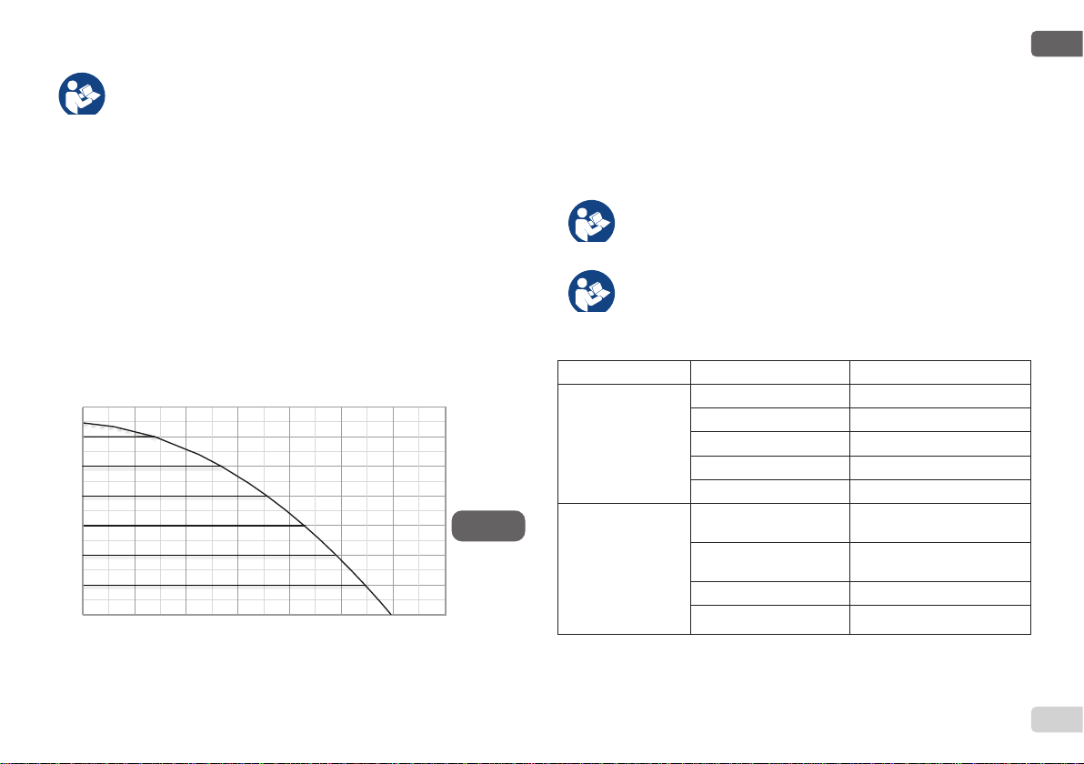
•• Operation at constant pressure;Operation at constant pressure;
•• Set-Point (desired value of constant pressure:SP = 3.0 barSet-Point (desired value of constant pressure:SP = 3.0 bar
•• Reduction of pressure to restart: RP = 0.3 barReduction of pressure to restart: RP = 0.3 bar
•• Anti-cycling function: DisabledAnti-cycling function: Disabled
However, these parameters and others can be set according to the sys-However, these parameters and others can be set according to the sys-
tem. All the settable values are illustrated in the par. 5-6-7: pressure, inter-tem. All the settable values are illustrated in the par. 5-6-7: pressure, inter-
vention of protections, rotation speed, etc.vention of protections, rotation speed, etc.
There are many other operating modes and accessory functions. Thanks There are many other operating modes and accessory functions. Thanks
to the dierent possible settings and the availability of congurable input to the dierent possible settings and the availability of congurable input
and output channels, it is possible to adapt the inverter operation to the and output channels, it is possible to adapt the inverter operation to the
requirements of various systems. See 5-6-7.requirements of various systems. See 5-6-7.
1.21.2 Integrated Expansion VesselIntegrated Expansion Vessel
The system is complete with an integrated expansion vessel with a total The system is complete with an integrated expansion vessel with a total
capacity of 2 litres. The main functions of the expansion vessel are:capacity of 2 litres. The main functions of the expansion vessel are:
•• to make the system elastic so as to protect it against water ham-to make the system elastic so as to protect it against water ham-
mer;mer;
•• to ensure a water reserve which, in the case of small leaks, main-to ensure a water reserve which, in the case of small leaks, main-
tains the pressure in the system for a longer time and spreads out tains the pressure in the system for a longer time and spreads out
needless restarts of the system which otherwise would be contin-needless restarts of the system which otherwise would be contin-
uous;uous;
•• when the utility is turned on, ensure the water pressure for the when the utility is turned on, ensure the water pressure for the
seconds that the system takes to switch on and reach the correct seconds that the system takes to switch on and reach the correct
rotation speed.rotation speed.
It is not a function of the integrated expansion vessel to ensure a water re-It is not a function of the integrated expansion vessel to ensure a water re-
serve such as to reduce interventions of the system (requests from the util-serve such as to reduce interventions of the system (requests from the util-
ity, not from a leak in the system). It is possible to add an expansion vessel ity, not from a leak in the system). It is possible to add an expansion vessel
with the capacity you prefer to the system, connecting it to a point on the with the capacity you prefer to the system, connecting it to a point on the
delivery system (not a suction point!). In the case of horizontal installation delivery system (not a suction point!). In the case of horizontal installation
it is possible to connect to the unused delivery outlet. When choosing the it is possible to connect to the unused delivery outlet. When choosing the
tank, consider that the quantity of water released will also depend on the tank, consider that the quantity of water released will also depend on the
parameters SP and RP that can be set on the system (par.6-7).parameters SP and RP that can be set on the system (par.6-7).
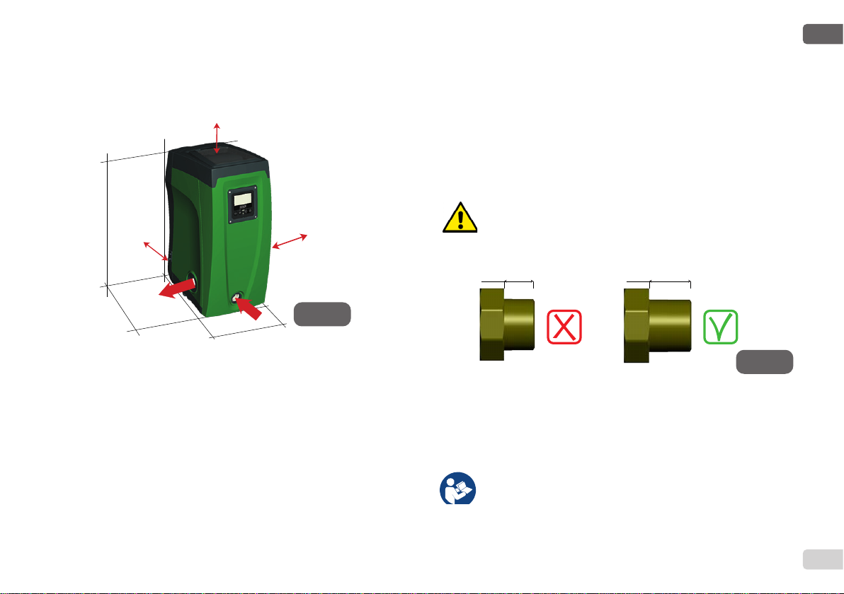
The expansion vessel is preloaded with pressurised air through the valve The expansion vessel is preloaded with pressurised air through the valve
accessible from the technical compartment (Fig.3, point 1). The preload accessible from the technical compartment (Fig.3, point 1). The preload
value with which the expansion vessel is supplied by the manufacturer is value with which the expansion vessel is supplied by the manufacturer is
in agreement with the parameters SP and RP set as default, and anyway it in agreement with the parameters SP and RP set as default, and anyway it
satises the following equation:satises the following equation:
Pair = SP – RP – 0.7bar Where:Pair = SP – RP – 0.7bar Where:
- Pair = air pressure value in bar - Pair = air pressure value in bar
- SP = Set Point (par.7.3) in bar - SP = Set Point (par.7.3) in bar
- RP = Reduction of pressure to restart - RP = Reduction of pressure to restart
(par. 7.5.1) in bar (par. 7.5.1) in bar
So, by the manufacturer: Pair = 3.0 – 0.3 – 0.7 = 2.0 barSo, by the manufacturer: Pair = 3.0 – 0.3 – 0.7 = 2.0 bar
If dierent values are set for the parameters SP and/or RP, regulate the If dierent values are set for the parameters SP and/or RP, regulate the
valve of the expansion vessel releasing or letting in air until the above valve of the expansion vessel releasing or letting in air until the above
equation is satised again (e.g.: SP=2.0bar; RP=0.3bar; release air from equation is satised again (e.g.: SP=2.0bar; RP=0.3bar; release air from
the expansion vessel until a pressure of 1.0 bar is reached on the valve).the expansion vessel until a pressure of 1.0 bar is reached on the valve).
Failure to respect the above equation may lead to malfunctions Failure to respect the above equation may lead to malfunctions
of the system or to premature breakage of the diaphragm inside of the system or to premature breakage of the diaphragm inside
the expansion vessel. the expansion vessel.
Considering the expansion vessel capacity of only 2 litres, any Considering the expansion vessel capacity of only 2 litres, any
operation to check the air pressure must be performed by con-operation to check the air pressure must be performed by con-
necting the pressure gauge very rapidly: on small volumes the necting the pressure gauge very rapidly: on small volumes the
loss of even a limited quantity of air can cause an appreciable loss of even a limited quantity of air can cause an appreciable
drop in pressure. The quality of the expansion vessel ensures drop in pressure. The quality of the expansion vessel ensures
the maintenance of the set air pressure value, proceed to check the maintenance of the set air pressure value, proceed to check
it only at calibration or if you are sure of a malfunction.it only at calibration or if you are sure of a malfunction.
Any operation to check and/or reset the air pressure must be per-Any operation to check and/or reset the air pressure must be per-
formed with the delivery system not under pressure: disconnect formed with the delivery system not under pressure: disconnect
the pump from the power supply and open the utility nearest to the pump from the power supply and open the utility nearest to
the pump, keeping it open until it no longer gives any water.the pump, keeping it open until it no longer gives any water.

ENGLISH
64
GB
The special structure of the expansion vessel ensures its quan-The special structure of the expansion vessel ensures its quan-
tity and duration over time, especially of the diaphragm which tity and duration over time, especially of the diaphragm which
is typically the component subject to wear for items of this type. is typically the component subject to wear for items of this type.
However, in the case of breakage, the entire expansion vessel However, in the case of breakage, the entire expansion vessel
must be replaced and exclusively by authorised personnel.must be replaced and exclusively by authorised personnel.
1.3 Integrated electropump1.3 Integrated electropump
The system has a built-in centrifugal electropump of the multi-impeller type The system has a built-in centrifugal electropump of the multi-impeller type
driven by a water-cooled three-phase electric motor. Cooling of the motor driven by a water-cooled three-phase electric motor. Cooling of the motor
with water rather than air ensures less noise in the system and the possi-with water rather than air ensures less noise in the system and the possi-
bility of locating it even in recesses without ventilation.bility of locating it even in recesses without ventilation.
The diagram in Fig. 6 shows the curves of the hydraulic performance for The diagram in Fig. 6 shows the curves of the hydraulic performance for
e.sybox. By automatically modulating the rotation speed of the electro-e.sybox. By automatically modulating the rotation speed of the electro-
pump, the inverter allows it to shift its work point according to necessities pump, the inverter allows it to shift its work point according to necessities
to any part of the area subtended by its curve, to keep the set pressure to any part of the area subtended by its curve, to keep the set pressure
valve constant (SP). The red curve shows the behaviour of the e.sybox valve constant (SP). The red curve shows the behaviour of the e.sybox
with set point at 3.0 bar.with set point at 3.0 bar.
Figure 6
0
10
20
30
40
50
60
70
0 20 40 60 80 100 120 14
0
H [m]
Q [l/min]
It results that, with SP = 3.0 bar, the system is able to ensure a constant It results that, with SP = 3.0 bar, the system is able to ensure a constant
pressure at the users that require ow rates respectively between 0 and pressure at the users that require ow rates respectively between 0 and
85 litres/minute. For higher ow rates the system works according to the 85 litres/minute. For higher ow rates the system works according to the
characteristic curve of the electropump at maximum rotation speed. For ow characteristic curve of the electropump at maximum rotation speed. For ow
rates lower than the limits described above, as well as ensuring constant rates lower than the limits described above, as well as ensuring constant
pressure, the system reduces the absorbed power and therefore the energy pressure, the system reduces the absorbed power and therefore the energy
consumption.consumption.
TThe above performances are to be considered measured at am-he above performances are to be considered measured at am-
bient temperature and water at about 20°C, during the rst 10 bient temperature and water at about 20°C, during the rst 10
minutes of motor operation, with water level at suction at a depth minutes of motor operation, with water level at suction at a depth
of no more than 1 metreof no more than 1 metre
As the suction depth increases, the performance of the electro-As the suction depth increases, the performance of the electro-
pump decreases. pump decreases.
1.4 Technical characteristics1.4 Technical characteristics
Text Parameter e.sybox
ELECTRIC POWER
SUPPLY
Voltage 1 x 220/240 ~ VAC
Frequency 50/60 Hz
Maximum current 10 A
Maximum power 1550 W
Leakage current to earth <2,5 [ma]
CONSTRUCTION
CHARACTERISTICS
Overall dimensions 565x265x352 mm without
feet
Empty weight (excluding
packaging) 24,8 kg
Protection class IP x4
Motor insulation class F

ENGLISH
GB
65
HYDRAULIC
PERFORMANCE
Maximum head 65 m
Maximum ow rate 120 l/min
Priming <5min at 8m
WORKING
CONDITIONS
Maximum working
pressure 8 bar
Liquid temperature max 40 °C
Environment temperature
max 50 °C
Storage environment
temperature -10÷60 °C
FUNCTIONALITY
AND
PROTECTIONS
Constant pressure
Wireless communication
Protection against dry running
Antifreeze protection
Anticycling protection
Motor overload protection
Protection against abnormal supply voltages
Protection against excess temperature
2- INSTALLATION2- INSTALLATION
TThe system is designed for indoor use: do not install the system he system is designed for indoor use: do not install the system
outdoors and/or directly exposed to atmospheric agents.outdoors and/or directly exposed to atmospheric agents.
The system is designed to be able to work in environments The system is designed to be able to work in environments
where the temperature remains between 0°C and 50°C (on con-where the temperature remains between 0°C and 50°C (on con-
dition that the electric power supply is ensured: see par. 7.6.14 dition that the electric power supply is ensured: see par. 7.6.14
“anti-freeze function”).“anti-freeze function”).
The system is suitable for treating drinking water.The system is suitable for treating drinking water.
The system cannot be used to pump salt water, sewage, inam-The system cannot be used to pump salt water, sewage, inam-
mable, corrosive or explosive liquids (e.g. petroleum, petrol, thin-mable, corrosive or explosive liquids (e.g. petroleum, petrol, thin-
ners), greases, oils or food products.ners), greases, oils or food products.
The system can take in water the level of which must not be at a The system can take in water the level of which must not be at a
depth greater than 8m (the height between the water level and depth greater than 8m (the height between the water level and
the pump suction mouth).the pump suction mouth).
Do not connect any pipe to the 1¼’’ mouth that houses the Do not connect any pipe to the 1¼’’ mouth that houses the
non-return valve, see g. 27.non-return valve, see g. 27.
If the system is used for the domestic water supply, respect the If the system is used for the domestic water supply, respect the
local regulations of the authorities responsible for the manage-local regulations of the authorities responsible for the manage-
ment of water resources.ment of water resources.
When choosing the installation site, check that:When choosing the installation site, check that:
•• The voltage and frequency on the pump’s technical data plate The voltage and frequency on the pump’s technical data plate
correspond to the values of the power supply system.correspond to the values of the power supply system.
•• The electrical connection is made in a dry place, far from any The electrical connection is made in a dry place, far from any
possible ooding.possible ooding.
•• The electrical system is provvided with a dierential switch The electrical system is provvided with a dierential switch
with I Δn ≤ 30 mA and that the earth system is ecient.with I Δn ≤ 30 mA and that the earth system is ecient.
If you are not sure of the absence of foreign bodies in the water to be If you are not sure of the absence of foreign bodies in the water to be
pumped, install a lter on the system intake that is suitable for catching pumped, install a lter on the system intake that is suitable for catching
impurities.impurities.
The installation of a lter on intake causes a decrease of the The installation of a lter on intake causes a decrease of the
system’s hydraulic performance proportional to the loss of load system’s hydraulic performance proportional to the loss of load
caused by the lter itself (generally the greater the ltering power, caused by the lter itself (generally the greater the ltering power,
the greater the fall in performance).the greater the fall in performance).
Choose the type of conguration you intend to use (vertical or horizontal) Choose the type of conguration you intend to use (vertical or horizontal)
considering the connections to the system, the position of the user inter-considering the connections to the system, the position of the user inter-
face panel, and the spaces available according to the indications below. face panel, and the spaces available according to the indications below.
Other types of installation conguration are possible using DAB accessory Other types of installation conguration are possible using DAB accessory
interfaces: see dedicated paragraph (par.9.2, 9.3).interfaces: see dedicated paragraph (par.9.2, 9.3).

ENGLISH
66
GB
2.1 - Vertical Conguration2.1 - Vertical Conguration
Remove the 4 support feet from the bottom tray of the packaging and Remove the 4 support feet from the bottom tray of the packaging and
screw them fully into their brass seats on face C. Put the system in place, screw them fully into their brass seats on face C. Put the system in place,
taking into account the dimensions in Fig.7.taking into account the dimensions in Fig.7.
•• The distance of at least 10mm between Face E of the system The distance of at least 10mm between Face E of the system
and any wall is obligatory to ensure ventilation through the grids and any wall is obligatory to ensure ventilation through the grids
provided.provided.
•• The distance of at least 270mm between Face B of the system The distance of at least 270mm between Face B of the system
and an obstruction is recommended so as to be able to carry out and an obstruction is recommended so as to be able to carry out
maintenance on the non-return valve without disconnecting the maintenance on the non-return valve without disconnecting the
system.system.
•• The distance of at least 200mm between Face A of the system The distance of at least 200mm between Face A of the system
and an obstruction is recommended so as to be able to remove and an obstruction is recommended so as to be able to remove
the door and gain access to the technical compartment.the door and gain access to the technical compartment.
If the surface is not at, unscrew the foot that is not touching and adjust If the surface is not at, unscrew the foot that is not touching and adjust
its height until it contacts the surface so as to ensure the stability of the its height until it contacts the surface so as to ensure the stability of the
system. The system must in fact be placed in a safe and stable position, system. The system must in fact be placed in a safe and stable position,
ensuring that its axis is vertical: it must not be in an inclined position. ensuring that its axis is vertical: it must not be in an inclined position.
10 mm
200 mm
270 mm
IN
OUT
580 mm
355 mm
265 mm
Figure 7
2.1.1 Hydraulic connections2.1.1 Hydraulic connections
Make the connection at input to the system through the mouth on Face F Make the connection at input to the system through the mouth on Face F
marked “IN” in Fig.7 (suction connection). Then remove the respective cap marked “IN” in Fig.7 (suction connection). Then remove the respective cap
with the aid of the accessory tool or with a screwdriver. with the aid of the accessory tool or with a screwdriver.
Make the connection at output from the system through the mouth on Face Make the connection at output from the system through the mouth on Face
F marked “OUT” in Fig.8 (delivery connection). Then remove the respec-F marked “OUT” in Fig.8 (delivery connection). Then remove the respec-
tive cap with the aid of the accessory tool or with a screwdriver.tive cap with the aid of the accessory tool or with a screwdriver.
All the hydraulic connections of the system to the plant to which it can be All the hydraulic connections of the system to the plant to which it can be
connected are of the threaded female type 1” GAS, made of brass.connected are of the threaded female type 1” GAS, made of brass.
IIf you intend to connect the product to the plant with ttings that f you intend to connect the product to the plant with ttings that
have a diameter larger than the normal 1” pipe (for example the have a diameter larger than the normal 1” pipe (for example the
ring nut in the case of ttings in 3 pieces), make sure that the 1” ring nut in the case of ttings in 3 pieces), make sure that the 1”
Gas male thread of the coupling protrudes at least 25mm from Gas male thread of the coupling protrudes at least 25mm from
the above diameter (see Fig.8)the above diameter (see Fig.8)
With reference to its position with respect to the water to be pumped, the With reference to its position with respect to the water to be pumped, the
installation of the system may be dened “above head” or “below head”. In installation of the system may be dened “above head” or “below head”. In
particular the installation is dened “above head” when the pump is placed particular the installation is dened “above head” when the pump is placed
at a level higher than the water to be pumped (e.g. pump on the surface at a level higher than the water to be pumped (e.g. pump on the surface
and water in a well); vice versa it is “below head” when the pump is placed and water in a well); vice versa it is “below head” when the pump is placed
at a level lower than the water to be pumped (e.g. overhead cistern and at a level lower than the water to be pumped (e.g. overhead cistern and
pump below).pump below).
If the vertical installation of the system is of the “over head” type, If the vertical installation of the system is of the “over head” type,
it is recommended to t a non-return valve in the suction section it is recommended to t a non-return valve in the suction section
of the system; this is to allow the operation of loading the system of the system; this is to allow the operation of loading the system
(par. 2.1.2).(par. 2.1.2).
< 25 mm > 25 mm
Figure 8

ENGLISH
GB
67
If the installation is of the “over head” type, install the suction pipe If the installation is of the “over head” type, install the suction pipe
from the water source to the pump in such a way as to avoid the from the water source to the pump in such a way as to avoid the
formation of goosenecks or siphons. Do not place the suction formation of goosenecks or siphons. Do not place the suction
pipe above the pump level (to avoid the formation of air bubbles pipe above the pump level (to avoid the formation of air bubbles
in the suction pipe). The suction pipe must draw at its entrance in the suction pipe). The suction pipe must draw at its entrance
at a depth of at least 30cm below the water level and must be at a depth of at least 30cm below the water level and must be
watertight along its whole length, as far as the entrance to the watertight along its whole length, as far as the entrance to the
electropump.electropump.
The suction and delivery pipes must be tted so that they do not The suction and delivery pipes must be tted so that they do not
exert any mechanical pressure on the pump.exert any mechanical pressure on the pump.
2.1.2 Loading Operation2.1.2 Loading Operation
Installation above head and below headInstallation above head and below head
Installation “above head” (par. 2.1.1): access the technical compartment Installation “above head” (par. 2.1.1): access the technical compartment
and, with the aid of the accessory tool (Fig.3_point 5) or with a screwdriv-and, with the aid of the accessory tool (Fig.3_point 5) or with a screwdriv-
er, remove the lling cap (Fig.3_point 6). Fill the system with clean water er, remove the lling cap (Fig.3_point 6). Fill the system with clean water
through the loading door, taking care to let the air out. If the non-return through the loading door, taking care to let the air out. If the non-return
valve on the suction pipe (recommended in paragraph 2.1.1) has been valve on the suction pipe (recommended in paragraph 2.1.1) has been
placed close to the system entry door, the quantity of water with which to placed close to the system entry door, the quantity of water with which to
ll the system should be 2.2 litres. It is recommended to t the non-return ll the system should be 2.2 litres. It is recommended to t the non-return
valve at the end of the suction pipe (foot valve) so as to be able to ll it valve at the end of the suction pipe (foot valve) so as to be able to ll it
quickly too during the loading operation. In this case the quantity of water quickly too during the loading operation. In this case the quantity of water
necessary for the loading operation will depend on the length of the suction necessary for the loading operation will depend on the length of the suction
pipe (2.2 litres + …).pipe (2.2 litres + …).
Installation “below head” (par. 2.1.1): if there are no check valves between Installation “below head” (par. 2.1.1): if there are no check valves between
the water deposit and the system (or if they are open), it loads automati-the water deposit and the system (or if they are open), it loads automati-
cally as soon as it is allowed to let out the trapped air. So slackening the cally as soon as it is allowed to let out the trapped air. So slackening the
lling cap (Fig.3_point 6) enough to vent the trapped air allows the system lling cap (Fig.3_point 6) enough to vent the trapped air allows the system
to load completely. You must survey the operation and close the loading to load completely. You must survey the operation and close the loading
door as soon as the water comes out (however it is recommended to t a door as soon as the water comes out (however it is recommended to t a
check valve in the section of the suction pipe and to use it to control the check valve in the section of the suction pipe and to use it to control the
loading operation with the cap open). Alternatively, in the case where the loading operation with the cap open). Alternatively, in the case where the
suction pipe is intercepted by a closed valve, the loading operation may be suction pipe is intercepted by a closed valve, the loading operation may be
carried out in a similar way to the one described for installation over head.carried out in a similar way to the one described for installation over head.
2.2 -2.2 - Horizontal CongurationHorizontal Conguration
Remove the 4 support feet from the bottom tray of the packaging and Remove the 4 support feet from the bottom tray of the packaging and
screw them fully into their brass seats on face E. Put the system in place, screw them fully into their brass seats on face E. Put the system in place,
taking into account the dimensions in Fig.9.taking into account the dimensions in Fig.9.
•• The distance of at least 270mm between Face B of the system The distance of at least 270mm between Face B of the system
and an obstruction is recommended so as to be able to carry out and an obstruction is recommended so as to be able to carry out
maintenance on the non-return valve without disconnecting the maintenance on the non-return valve without disconnecting the
system.system.
•• The distance of at least 200mm between Face A of the system The distance of at least 200mm between Face A of the system
and an obstruction is recommended so as to be able to remove and an obstruction is recommended so as to be able to remove
the door and gain access to the technical compartment.the door and gain access to the technical compartment.
•• The distance of at least 10mm between Face D of the system The distance of at least 10mm between Face D of the system
and an obstruction is obligatory to let out the power supply cable.and an obstruction is obligatory to let out the power supply cable.
If the surface is not at, unscrew the foot that is not touching and adjust If the surface is not at, unscrew the foot that is not touching and adjust
its height until it contacts the surface so as to ensure the stability of the its height until it contacts the surface so as to ensure the stability of the
system. The system must in fact be placed in a safe and stable position, system. The system must in fact be placed in a safe and stable position,
ensuring that its axis is vertical: it must not be in an inclined position. ensuring that its axis is vertical: it must not be in an inclined position.
10 mm
200 mm
270 mm
OUT 1
OUT 2
IN
565 mm
370 mm
265 mm
Figure 9

ENGLISH
68
GB
2.2.1 Hydraulic connections2.2.1 Hydraulic connections
Make the connection at input to the system through the mouth on Face C Make the connection at input to the system through the mouth on Face C
marked “IN” in Fig.9 (suction connection). Then remove the respective cap marked “IN” in Fig.9 (suction connection). Then remove the respective cap
with the aid of the accessory tool or with a screwdriver.with the aid of the accessory tool or with a screwdriver.
Make the connection at output from the system through the mouth on Face C Make the connection at output from the system through the mouth on Face C
marked “OUT 1” in Fig.9 and/or through the mouth on Face D marked “OUT marked “OUT 1” in Fig.9 and/or through the mouth on Face D marked “OUT
2” in Fig.9 (delivery connection). In this conguration either of the 2 mouths can 2” in Fig.9 (delivery connection). In this conguration either of the 2 mouths can
be used as an alternative to the other (depending on the convenience of the be used as an alternative to the other (depending on the convenience of the
installation), or simultaneously (dual delivery system). So remove the cap(s) installation), or simultaneously (dual delivery system). So remove the cap(s)
from the door(s) you intend to use with the aid of the accessory tool or with a from the door(s) you intend to use with the aid of the accessory tool or with a
screwdriver.screwdriver.
All the hydraulic connections of the system to the plant to which it can be con-All the hydraulic connections of the system to the plant to which it can be con-
nected are of the threaded female type 1” GAS, made of brass.nected are of the threaded female type 1” GAS, made of brass.
See WARNING for Figure 8.See WARNING for Figure 8.
2.2.2 Orientation of the Interface Panel2.2.2 Orientation of the Interface Panel
The Interface Panel has been designed so that it can be oriented in the The Interface Panel has been designed so that it can be oriented in the
direction where it is most convenient for the user to read: its square shape direction where it is most convenient for the user to read: its square shape
allows it to be rotated from 90° to 90° (Fig.10).allows it to be rotated from 90° to 90° (Fig.10). •• Disengage the 4 screws at the corners of the panel using the hex Disengage the 4 screws at the corners of the panel using the hex
wrench provided with the accessory tool.wrench provided with the accessory tool.
•• Do not remove the screws, just disengage them from the thread Do not remove the screws, just disengage them from the thread
on the product body.on the product body.
•• Be careful not to drop the screws into the system.Be careful not to drop the screws into the system.
•• Move the panel away, taking care not to pull on the signal trans-Move the panel away, taking care not to pull on the signal trans-
mission cable.mission cable.
•• Reposition the panel in its seat at the preferred angle taking care Reposition the panel in its seat at the preferred angle taking care
not to pinch the cable.not to pinch the cable.
•• Tighten the 4 screws with the wrench.Tighten the 4 screws with the wrench.
Figure 10

ENGLISH
GB
69
2.2.3 Loading Operation2.2.3 Loading Operation
Installation above head and below headInstallation above head and below head
With reference to its position with respect to the water to be pumped, the instal-With reference to its position with respect to the water to be pumped, the instal-
lation of the system may be dened “above head” or “below head”. In particular lation of the system may be dened “above head” or “below head”. In particular
the installation is dened “above head” when the pump is placed at a level the installation is dened “above head” when the pump is placed at a level
higher than the water to be pumped (e.g. pump on the surface and water in higher than the water to be pumped (e.g. pump on the surface and water in
a well); vice versa it is “below head” when the pump is placed at a level lower a well); vice versa it is “below head” when the pump is placed at a level lower
than the water to be pumped (e.g. overhead cistern and pump below).than the water to be pumped (e.g. overhead cistern and pump below).
Installation “above head”: with the aid of the accessory tool (Fig.3_point 5) or Installation “above head”: with the aid of the accessory tool (Fig.3_point 5) or
with a screwdriver, remove the lling cap which, for the horizontal conguration, with a screwdriver, remove the lling cap which, for the horizontal conguration,
is the one on Face F (Fig.1). Fill the system with clean water through the load-is the one on Face F (Fig.1). Fill the system with clean water through the load-
ing door, taking care to let the air out. The quantity of water with which to ll the ing door, taking care to let the air out. The quantity of water with which to ll the
system must be at least 1.5 litres. It is recommended to t a non-return valve at system must be at least 1.5 litres. It is recommended to t a non-return valve at
the end of the suction pipe (foot valve) so as to be able to ll it quickly too dur-the end of the suction pipe (foot valve) so as to be able to ll it quickly too dur-
ing the loading operation. In this case the quantity of water necessary for the ing the loading operation. In this case the quantity of water necessary for the
loading operation will depend on the length of the suction pipe (1.5 litres + …).loading operation will depend on the length of the suction pipe (1.5 litres + …).
Installation “below head”: if there are no check valves between the water de-Installation “below head”: if there are no check valves between the water de-
posit and the system (or if they are open), it loads automatically as soon as it is posit and the system (or if they are open), it loads automatically as soon as it is
allowed to let out the trapped air. So slackening the lling cap (Face F - Fig.3) allowed to let out the trapped air. So slackening the lling cap (Face F - Fig.3)
enough to vent the air allows the system to load completely. To slacken the enough to vent the air allows the system to load completely. To slacken the
Figure 11
x4
x4
cap, use the accessory tool (Fig.3_point 5) or a screwdriver. You must survey cap, use the accessory tool (Fig.3_point 5) or a screwdriver. You must survey
the operation and close the loading door as soon as the water comes out (how-the operation and close the loading door as soon as the water comes out (how-
ever it is recommended to t a check valve in the section of the suction pipe ever it is recommended to t a check valve in the section of the suction pipe
and to use it to control the loading operation with the cap loose). Alternatively, and to use it to control the loading operation with the cap loose). Alternatively,
in the case where the suction pipe is intercepted by a closed valve, the loading in the case where the suction pipe is intercepted by a closed valve, the loading
operation may be carried out in a similar way to the one described for installa-operation may be carried out in a similar way to the one described for installa-
tion over head.tion over head.
3 - COMMISSIONING3 - COMMISSIONING
Maximum working pressure 8 bar.Maximum working pressure 8 bar.
The intake depth must not exceed 8m.The intake depth must not exceed 8m.
3.1 - Electrical Connections3.1 - Electrical Connections
To improve immunity to the possible noise radiated towards other appli-To improve immunity to the possible noise radiated towards other appli-
ances it is recommended to use a separate electrical duct to supply the ances it is recommended to use a separate electrical duct to supply the
product.product.
The line voltage may change when the electropump is started. The line voltage may change when the electropump is started.
The line voltage may undergo variations depending on other de-The line voltage may undergo variations depending on other de-
vices connected to it and on the quality of the line.vices connected to it and on the quality of the line.
It is recommended to carry out installation as indicated in the manual, in It is recommended to carry out installation as indicated in the manual, in
compliance with the laws, directives and standards in force in the place of compliance with the laws, directives and standards in force in the place of
use and depending on the application. The product contains an inverter in-use and depending on the application. The product contains an inverter in-
side which there are continuous voltages and currents with high-frequency side which there are continuous voltages and currents with high-frequency
components (see table 1a). components (see table 1a).
Type of possible fault currents to earth
Alternating Unipolar
pulsed Direct
With high-
frequency
components
XXXX
Table 1a

ENGLISH
70
GB
Figure 11 - bis Installation example
The thermal magnetic circuit breaker must be correctly sized (see Electri-The thermal magnetic circuit breaker must be correctly sized (see Electri-
cal Characteristics).cal Characteristics).
The appliance must be connected to a main switch that cuts o all the The appliance must be connected to a main switch that cuts o all the
power supply poles. When the switch is in o position, the distance sepa-power supply poles. When the switch is in o position, the distance sepa-
rating each contact must respect the indications in table 1b.rating each contact must respect the indications in table 1b.
Minimum distance between the contacts of the power switch
Minimum distance [mm] >3
3.2 Conguration of the Integrated Inverter3.2 Conguration of the Integrated Inverter
The system is congured by the manufacturer to satisfy the majority of The system is congured by the manufacturer to satisfy the majority of
installation cases, that is:installation cases, that is:
•• operation at constant pressure;operation at constant pressure;
•• Set-Point (desired value of constant pressure): SP = 3.0 barSet-Point (desired value of constant pressure): SP = 3.0 bar
•• Reduction of pressure to restart: RP = 0.3 barReduction of pressure to restart: RP = 0.3 bar
•• Anti-cycling function: DisabledAnti-cycling function: Disabled
However, all these parameters and many others can be set by the user. However, all these parameters and many others can be set by the user.
Table 1b
There are many other operating modes and accessory functions. Thanks There are many other operating modes and accessory functions. Thanks
to the dierent possible settings and the availability of congurable input to the dierent possible settings and the availability of congurable input
and output channels, it is possible to adapt the inverter operation to the and output channels, it is possible to adapt the inverter operation to the
requirements of various systems. See par. 5-6-7requirements of various systems. See par. 5-6-7
For the denition of the parameters SP and RP, the pressure at For the denition of the parameters SP and RP, the pressure at
which the system starts has the value:which the system starts has the value:
Pstart = SP – RPPstart = SP – RP For example: 3.0 – 0.3 = 2.7 bar For example: 3.0 – 0.3 = 2.7 bar
in the default congurationin the default conguration
The system does not work if the utility is at a height higher than the equiv-The system does not work if the utility is at a height higher than the equiv-
alent in metres of water column of the Pstart (consider 1 bar = 10 m water alent in metres of water column of the Pstart (consider 1 bar = 10 m water
column): for the default conguration, if the utility is at a height of at least column): for the default conguration, if the utility is at a height of at least
27m the system does not start.27m the system does not start.
3.3 - Priming3.3 - Priming
The priming of a pump is the phase during which the machine attempts to The priming of a pump is the phase during which the machine attempts to
ll the body and the suction pipe with water. If the operation is successful ll the body and the suction pipe with water. If the operation is successful
the machine can work regularly.the machine can work regularly.
Once the pump has been lled (par. 2.1.2, 2.2.3) and the device has been Once the pump has been lled (par. 2.1.2, 2.2.3) and the device has been
congured (par. 3.2), it is possible to connect the electric power supply congured (par. 3.2), it is possible to connect the electric power supply
after having opened at least one utility on delivery.after having opened at least one utility on delivery.
The system starts and checks the presence of water in delivery for the rst The system starts and checks the presence of water in delivery for the rst
10 seconds.10 seconds.
If a ow of water is detected in delivery, the pump is primed and starts its If a ow of water is detected in delivery, the pump is primed and starts its
regular work. This is the typical case of installation below head (par. 2.1.2, regular work. This is the typical case of installation below head (par. 2.1.2,
2.2.3). The utility opened in delivery from which the pumped water is com-2.2.3). The utility opened in delivery from which the pumped water is com-
ing out can be closed.ing out can be closed.
If a regular ow in delivery is not detected after 10 seconds, the system If a regular ow in delivery is not detected after 10 seconds, the system
asks for conrmation to enter the priming procedure (typical case of instal-asks for conrmation to enter the priming procedure (typical case of instal-
lation above head par. 2.1.2, 2.2.3). lation above head par. 2.1.2, 2.2.3). Or:Or:

ENGLISH
GB
71
When “+” is pressed the pump enters the priming procedure: it starts work-When “+” is pressed the pump enters the priming procedure: it starts work-
ing for a maximum time of 5 minutes during which the safety block for dry ing for a maximum time of 5 minutes during which the safety block for dry
operation is not tripped. The priming time depends on various parameters, operation is not tripped. The priming time depends on various parameters,
the most inuential of which are the depth of the water level from which it the most inuential of which are the depth of the water level from which it
is drawing, the diameter of the suction pipe, the water-tightness of the suc-is drawing, the diameter of the suction pipe, the water-tightness of the suc-
tion pipe. On condition that a suction pipe is used that is no smaller than tion pipe. On condition that a suction pipe is used that is no smaller than
1” and that it is well sealed (with no holes or joins from which it can take in 1” and that it is well sealed (with no holes or joins from which it can take in
air), the product has been studied to manage to prime in water conditions air), the product has been studied to manage to prime in water conditions
up to 8m in depth, in a time of less than 5 minutes. As soon as the product up to 8m in depth, in a time of less than 5 minutes. As soon as the product
detects a regular ow in delivery, it leaves the priming procedure and starts detects a regular ow in delivery, it leaves the priming procedure and starts
its regular work. The utility opened in delivery from which the pumped wa-its regular work. The utility opened in delivery from which the pumped wa-
ter is coming out can be closed. If after 5 minutes of the procedure the ter is coming out can be closed. If after 5 minutes of the procedure the
product is still not primed, the interface display sends a failure message. product is still not primed, the interface display sends a failure message.
Disconnect the power supply, load the product adding new water, wait 10 Disconnect the power supply, load the product adding new water, wait 10
minutes and repeat the procedure from the moment you put the plug in minutes and repeat the procedure from the moment you put the plug in
the socket.the socket.
Press “-“ to conrm that you do not want to start the priming procedure. Press “-“ to conrm that you do not want to start the priming procedure.
The product remains in alarm statusThe product remains in alarm status
OperationOperation
Once the electropump is primed, the system starts regular operation ac-Once the electropump is primed, the system starts regular operation ac-
cording to the congured parameters: it starts automatically when the tap cording to the congured parameters: it starts automatically when the tap
is turned on, supplies water at the set pressure (SP), keeps the pressure is turned on, supplies water at the set pressure (SP), keeps the pressure
constant even when other taps are turned on, stops automatically after constant even when other taps are turned on, stops automatically after
time T2 once the switching o conditions are reached (T2 can be set by time T2 once the switching o conditions are reached (T2 can be set by
the user, factory value 10 sec).the user, factory value 10 sec).
4 - PROTECTION SYSTEMS4 - PROTECTION SYSTEMS
IThe device is equipped with protection systems to preserve the pump, the IThe device is equipped with protection systems to preserve the pump, the
motor, the supply line and the inverter. If one or more protections trip, the motor, the supply line and the inverter. If one or more protections trip, the
one with the highest priority is immediately notied on the display. Depend-one with the highest priority is immediately notied on the display. Depend-
ing on the type of error the motor may stop, but when normal conditions ing on the type of error the motor may stop, but when normal conditions
are restored the error status may be cancelled immediately or only after a are restored the error status may be cancelled immediately or only after a
certain time, following an automatic reset.certain time, following an automatic reset.
In the case of blockage due to water lack (BL), blockage due to motor over-In the case of blockage due to water lack (BL), blockage due to motor over-
load (OC), blockage due to direct short circuit between the motor phases load (OC), blockage due to direct short circuit between the motor phases
(SC), you can try to exit the error conditions manually by simultaneously (SC), you can try to exit the error conditions manually by simultaneously
pressing and releasing the + and – keys. If the error condition remains, you pressing and releasing the + and – keys. If the error condition remains, you
must take steps to eliminate the cause of the fault. must take steps to eliminate the cause of the fault.
In the event of blocking due to one of the internal errors E18, E19, E20, In the event of blocking due to one of the internal errors E18, E19, E20,
E21 it is necessary to wait 15 minutes with the machine powered until the E21 it is necessary to wait 15 minutes with the machine powered until the
blocked status is automatically reset.blocked status is automatically reset.
Alarm in the fault log
Display indication Description
PD Irregular switching o
FA Problems in the cooling system
Blockage conditions
Display indication Description
PH Cutout due to pump overheating
BL Blockage due to water lack
BP1 Blockage due to reading error on the internal pressure sensor
PB Blockage due to supply voltage outside specications
OT Blockage due to overheating of the power stages
OC Blockage due to motor overload
SC Blockage due to short circuit between the motor phases
ESC Blockage due to short circuit to earth
HL Hot liquid
NC Blockage due to motor disconnected
Ei Blockage due to i-th internal error
Vi Blockage due to i-th internal voltage out of tolerance
EY Block for cyclicality abnormal detected on the system
Table 1: Alarms
Table 2: Indications of blockages

ENGLISH
72
GB
4.1 - Description of blockages4.1 - Description of blockages
4.1.1 -4.1.1 - “BL” Anti Dry-Run (Protection against dry running)“BL” Anti Dry-Run (Protection against dry running)
In the case of lack of water the pump is stopped automatically after the In the case of lack of water the pump is stopped automatically after the
time TB. This is indicated by the red “Alarm” led and by the letters “BL” on time TB. This is indicated by the red “Alarm” led and by the letters “BL” on
the display.the display.
After having restored the correct ow of water you can try to leave the After having restored the correct ow of water you can try to leave the
protective block manually by pressing the “+” and “-“ keys simultaneously protective block manually by pressing the “+” and “-“ keys simultaneously
and then releasing them.and then releasing them.
If the alarm status remains, or if the user does not intervene by restoring If the alarm status remains, or if the user does not intervene by restoring
the ow of water and resetting the pump, the automatic restart will try to the ow of water and resetting the pump, the automatic restart will try to
restart the pump.restart the pump.
If the parameter SP is not correctly set, the protection against If the parameter SP is not correctly set, the protection against
water lack may not work correctly.water lack may not work correctly.
4.1.2 - Anti-Cycling (Protection against continuous cycles without 4.1.2 - Anti-Cycling (Protection against continuous cycles without
utility request)utility request)
If there are leaks in the delivery section of the plant, the system starts and If there are leaks in the delivery section of the plant, the system starts and
stops cyclically even if no water is intentionally being drawn: even just a stops cyclically even if no water is intentionally being drawn: even just a
slight leak (a few ml) can cause a fall in pressure which in turn starts the slight leak (a few ml) can cause a fall in pressure which in turn starts the
electropump.electropump.
The electronic control of the system is able to detect the presence of the The electronic control of the system is able to detect the presence of the
leak, based on its recurrence. leak, based on its recurrence.
The Anti-Cycling function can be excluded or activated in Basic or Smart The Anti-Cycling function can be excluded or activated in Basic or Smart
mode (par 7.6.12).mode (par 7.6.12).
In Basic mode, once the condition of recurrence is detected the pump In Basic mode, once the condition of recurrence is detected the pump
stops and remains waiting to be manually reset. This condition is commu-stops and remains waiting to be manually reset. This condition is commu-
nicated to the user by the lighting of the red “Alarm” led and the appear-nicated to the user by the lighting of the red “Alarm” led and the appear-
ance of the word “ANTICYCLING” on the display. After the leak has been ance of the word “ANTICYCLING” on the display. After the leak has been
removed, you can manually force restart by simultaneously pressing and removed, you can manually force restart by simultaneously pressing and
releasing the “+” and “-“ keys.releasing the “+” and “-“ keys.
In Smart mode, once the leak condition is detected, the parameter RP is In Smart mode, once the leak condition is detected, the parameter RP is
increased to decrease the number of starts over time.increased to decrease the number of starts over time.
4.1.3 - Anti-Freeze (Protection against freezing of water in the sys4.1.3 - Anti-Freeze (Protection against freezing of water in the system)tem)
The change of state of water from liquid to solid involves an increase in The change of state of water from liquid to solid involves an increase in
volume. It is therefore essential to ensure that the system does not remain volume. It is therefore essential to ensure that the system does not remain
full of water with temperatures close to freezing point, to avoid breakages full of water with temperatures close to freezing point, to avoid breakages
of the system. This is the reason why it is recommended to empty any of the system. This is the reason why it is recommended to empty any
electropump that is going to remain unused during the winter. However, electropump that is going to remain unused during the winter. However,
this system has a protection that prevents ice formation inside by activat-this system has a protection that prevents ice formation inside by activat-
ing the electropump when the temperature falls to values close to freezing ing the electropump when the temperature falls to values close to freezing
point. In this way the water inside is heated and freezing prevented.point. In this way the water inside is heated and freezing prevented.
The Anti-Freeze protection works only if the system is regularly The Anti-Freeze protection works only if the system is regularly
fed: with the plug disconnected or in the absence of current the fed: with the plug disconnected or in the absence of current the
protection cannot work.protection cannot work.
However, it is advised not to leave the system full during long peri-However, it is advised not to leave the system full during long peri-
ods of inactivity: drain the system accurately through the drainage ods of inactivity: drain the system accurately through the drainage
cap (Fig.1 Face E) and put it away in a sheltered place.cap (Fig.1 Face E) and put it away in a sheltered place.
4.1.4 - “BP1” Blockage due to fault of the internal pressure sensor4.1.4 - “BP1” Blockage due to fault of the internal pressure sensor
If the device detects a fault in the pressure sensor the pump remains If the device detects a fault in the pressure sensor the pump remains
blocked and the error signal “BP1” is given. This status begins as soon as blocked and the error signal “BP1” is given. This status begins as soon as
the problem is detected and ends automatically when correct conditions the problem is detected and ends automatically when correct conditions
have been restored.have been restored.
4.1.5 - “PB” Blockage due to supply voltage outside specications4.1.5 - “PB” Blockage due to supply voltage outside specications
This occurs when the allowed line voltage at the supply terminal assumes This occurs when the allowed line voltage at the supply terminal assumes
values outside the specications. It is reset only automatically when the values outside the specications. It is reset only automatically when the
voltage at the terminal returns within the allowed valuesvoltage at the terminal returns within the allowed values..
4.1.6 - “SC” Blockage due to short circuit between the motor phases4.1.6 - “SC” Blockage due to short circuit between the motor phases
The device is provided with protection against the direct short circuit which The device is provided with protection against the direct short circuit which
may occur between the motor phases. When this blockage is indicated may occur between the motor phases. When this blockage is indicated
you can attempt to restore operation by simultaneously holding down the + you can attempt to restore operation by simultaneously holding down the +
and – keys, but this will not have any eect until 10 seconds have passed and – keys, but this will not have any eect until 10 seconds have passed
since the moment the short circuit occurred.since the moment the short circuit occurred.

ENGLISH
GB
73
4.2 - Manual reset of error conditions4.2 - Manual reset of error conditions
In error status, the user can cancel the error by forcing a new attempt, In error status, the user can cancel the error by forcing a new attempt,
pressing and then releasing the + and – keys.pressing and then releasing the + and – keys.
4.3 - Self-reset of error conditions4.3 - Self-reset of error conditions
For some malfunctions and blockage conditions, the system attempts au-For some malfunctions and blockage conditions, the system attempts au-
tomatic self-reset.tomatic self-reset.
The auto self-reset procedure concerns in particular:The auto self-reset procedure concerns in particular:
“BL” Blockage due to water lack“BL” Blockage due to water lack
“PB” Blockage due to line voltage outside specications“PB” Blockage due to line voltage outside specications
“OT” Blockage due to overheating of the power stages“OT” Blockage due to overheating of the power stages
“OC” Blockage due to motor overload“OC” Blockage due to motor overload
“BP” Blockage due to fault of the pressure sensor“BP” Blockage due to fault of the pressure sensor
For example, if the system is blocked due to water lack, the device auto-For example, if the system is blocked due to water lack, the device auto-
matically starts a test procedure to check whether the machine is really matically starts a test procedure to check whether the machine is really
left denitively and permanently dry. If during the sequence of operations left denitively and permanently dry. If during the sequence of operations
an attempted reset is successful (for example, the water comes back), the an attempted reset is successful (for example, the water comes back), the
procedure is interrupted and normal operation is resumed.procedure is interrupted and normal operation is resumed.
Table 21 shows the sequences of the operations performed by the device Table 21 shows the sequences of the operations performed by the device
for the dierent types of blockage.for the dierent types of blockage.
Automatic resets of error conditions
Display indica-
tion Description Automatic reset sequence
BL Blockage due to water
lack
- One attempt every 10 minutes for a
total of 6 attempts
- One attempt every hour for a total of
24 attempts
- One attempt every 24 hours for a total
of 30 attempts
PB Blockage due to line
voltage outside speci-
cations
- It is reset when it returns to a specic
voltage
OT Blockage due to over-
heating of the power
stages
-It is reset when the temperature of
the power stages returns within the
specications.
OC Blockage due to motor
overload
- One attempt every 10 minutes for a
total of 6 attempts
- One attempt every hour for a total of
24 attempts
- One attempt every 24 hours for a total
of 30 attempts
5 - INVERTER ELECTRONIC CONTROL AND USER INTERFACE5 - INVERTER ELECTRONIC CONTROL AND USER INTERFACE
The inverter makes the system work at constant pressure. This The inverter makes the system work at constant pressure. This
regulation is appreciated if the hydraulic plant downstream from regulation is appreciated if the hydraulic plant downstream from
the system is suitably sized. Plants made with pipes with too the system is suitably sized. Plants made with pipes with too
small a section introduce load losses that the equipment cannot small a section introduce load losses that the equipment cannot
compensate; the result is that the pressure is constant on the compensate; the result is that the pressure is constant on the
sensors but not on the utility.sensors but not on the utility.
Plants that are excessively deformable can create the onset of Plants that are excessively deformable can create the onset of
oscillations; if this occurs, the problem can be solved by adjusting oscillations; if this occurs, the problem can be solved by adjusting
the control parameters “GP” and “GI” (see par 7.6.4 - GP: Pro-the control parameters “GP” and “GI” (see par 7.6.4 - GP: Pro-
portional gain coecient and 7.6.5 - GI: Integral gain coecient).portional gain coecient and 7.6.5 - GI: Integral gain coecient).
5.1 - Operation with control unit 5.1 - Operation with control unit
e.sybox, alone or in a pumping unit, may be connected by means of wire-e.sybox, alone or in a pumping unit, may be connected by means of wire-
less communication to a remote unit referred to below as a control unit. less communication to a remote unit referred to below as a control unit.
Depending on the model, the control unit oers a variety of functions.Depending on the model, the control unit oers a variety of functions.
The possible control units are:The possible control units are:
• e.sylink• e.sylink
Table 3: Self-reset of blockages

ENGLISH
74
GB
Combining one or more e.syboxes with a control unit allows the use of:Combining one or more e.syboxes with a control unit allows the use of:
• Digital inputs• Digital inputs
• Relay outputs• Relay outputs
• Remote pressure sensor• Remote pressure sensor
• Ethernet network connection• Ethernet network connection
Below, the combination of functions listed above, made available by the Below, the combination of functions listed above, made available by the
various types of control unit, will be referred to as “control unit functionsvarious types of control unit, will be referred to as “control unit functions
5.1.1 - Functions made available by control units5.1.1 - Functions made available by control units
The functions made available are specied in Table 4, Functions made The functions made available are specied in Table 4, Functions made
available by control units available by control units
Functions e.sylink
Opto-isolated digital inputs •
Output relay with NO contact •
Remote pressure sensor •
Network connection
5.1.2 -5.1.2 - Electrical connections of utility inputs and outputsElectrical connections of utility inputs and outputs
See control unit manual.See control unit manual.
5.1.3 - Safety mode operation5.1.3 - Safety mode operation
When using the input or remote sensor functions, in the event of a commu-When using the input or remote sensor functions, in the event of a commu-
nications downage or control unit error, the e.sysbox and control unit will nications downage or control unit error, the e.sysbox and control unit will
switch to safety mode, adopting the conguration considered least dam-switch to safety mode, adopting the conguration considered least dam-
aging. When safety mode comes into operation, a ashing icon showing a aging. When safety mode comes into operation, a ashing icon showing a
cross inside a triangle appears on the display.cross inside a triangle appears on the display.
The way in which the e.sysbox responds to a communications downage is The way in which the e.sysbox responds to a communications downage is
explained in the table below.explained in the table below.
Tab. 4: Functions made available by control units
e.sybox
setting
e.sybox response
No control
unit asso-
ciated
Control unit associated
Communication with control
unit No commu-
nication with
control unit,
or control
unit error
Safety mode
Function
activated
(by means
of input or
menu)
Function not
activated
(by means
of input or
menu)
In=0 Input func-
tion disabled
No action No action No action No action
In(2)=1, 2
Low water level
indicated by
oat switch
No action System in
stop status F1
No action System in
stop status(1)
in(2)=3, 4
Pauxn auxiliary
setpoint
No action Activation of
correspond-
ing auxiliary
setpoint
No action Activation of
lowest auxil-
iary setpoint
pressure set
in(2)=5, 6
Disable system
No action System in
stop status F3
No action System in
stop status(1)
in(2) =7, 8
Disable system
+ fault and
warning reset
No action System in
stop status
F3 + fault and
warning reset
No action System in
stop status(1)
in =9
Fault and warn-
ing reset
No action Fault and
warning reset
No action No action

ENGLISH
GB
75
in(2)=10, 11, 12,
13 Kiwa function
(low input pres-
sure signal)
No action System in
stop status F4
No action System in
stop status(1)
PR=0
Remote pres-
sure sensor
disabled
No action No action No action No action
PR=1
Use of remote
pressure sensor
No action Setpoint
on remote
sensor
No action Remote set-
point ignored
(1)(1) The activation of the function relating to this box + any other function in The activation of the function relating to this box + any other function in
safety mode triggers a system stop. In this case, the system displays the safety mode triggers a system stop. In this case, the system displays the
highest priority stoppage cause. highest priority stoppage cause.
(2)(2) The numbers separated by commas indicate the possible setting values The numbers separated by commas indicate the possible setting values
for the function concernedfor the function concerned
Instead, as regards the control unit, if there is a loss of communication it Instead, as regards the control unit, if there is a loss of communication it
lights relay 1 depending on the settings of O1 (see tab 20), considering the lights relay 1 depending on the settings of O1 (see tab 20), considering the
lack of communication an error condition.lack of communication an error condition.
5.1.4 - Control unit function setup5.1.4 - Control unit function setup
The default value of all the inputs and the remote pressure sensor is DISA-The default value of all the inputs and the remote pressure sensor is DISA-
BLE, so before they can be used, they must be activated by the user; see BLE, so before they can be used, they must be activated by the user; see
point 7.6.15 - Setup of auxiliary digital inputs IN1, IN2, IN3, IN4, pressure point 7.6.15 - Setup of auxiliary digital inputs IN1, IN2, IN3, IN4, pressure
sensor point 7.5.6 - PR: Remote pressure sensor. sensor point 7.5.6 - PR: Remote pressure sensor.
The outputs are enabled by default, see output functions point 7.6.16 - The outputs are enabled by default, see output functions point 7.6.16 -
Setup of outputs OUT1, OUT2.Setup of outputs OUT1, OUT2.
If no control unit has been associated, the input, output and remote pres-If no control unit has been associated, the input, output and remote pres-
sure sensor functions are ignored and have no eect, regardless of their sure sensor functions are ignored and have no eect, regardless of their
setups. setups.
The control unit parameters (inputs, outputs and pressure sensors) can be The control unit parameters (inputs, outputs and pressure sensors) can be
set even if the connection is down or even not made.set even if the connection is down or even not made.
Tab.5 Triggering of safety mode
If the control unit is associated (it is included in the e.sybox’s wireless net-If the control unit is associated (it is included in the e.sybox’s wireless net-
work) but is not present or not visible due to problems, when the param-work) but is not present or not visible due to problems, when the param-
eters related to these functions are set at a value other than disable they eters related to these functions are set at a value other than disable they
blink to indicate that they will not be able to full their functions.blink to indicate that they will not be able to full their functions.
5.1.5 - Association and disassociation of e.sybox and control unit5.1.5 - Association and disassociation of e.sybox and control unit
The procedure for associating a control unit to an e.sybox is the same as The procedure for associating a control unit to an e.sybox is the same as
for associating an e.sybox:for associating an e.sybox:
locate the AS page of the installer menu and hold down the “+” key for 5 locate the AS page of the installer menu and hold down the “+” key for 5
sec., until the blue LED blinks (whether the e.sybox is stand-alone or in a sec., until the blue LED blinks (whether the e.sybox is stand-alone or in a
group). After this, press the ► key for 5 sec. until the blue communication group). After this, press the ► key for 5 sec. until the blue communication
LED starts to blink. As soon as the connection has been established, the LED starts to blink. As soon as the connection has been established, the
LED becomes steady and the e.sylink symbol appears on the AS page of LED becomes steady and the e.sylink symbol appears on the AS page of
the e.sybox.the e.sybox.
The procedure for disassociating the e.sylink is the same as for the e.sy-The procedure for disassociating the e.sylink is the same as for the e.sy-
box: locate the AS page of the installer menu and hold down the “-” key for box: locate the AS page of the installer menu and hold down the “-” key for
5 sec; this will eliminate all the wireless connections present.5 sec; this will eliminate all the wireless connections present.

ENGLISH
76
GB
6 - THE KEYPAD AND THE DISPLAY6 - THE KEYPAD AND THE DISPLAY
The user interface is composed of a keypad with 128x240 pixel LCD dis-The user interface is composed of a keypad with 128x240 pixel LCD dis-
play and with POWER, COMM, ALARM warning leds as can be seen in play and with POWER, COMM, ALARM warning leds as can be seen in
Figure 12.Figure 12.
The display shows the values and the statuses of the device, with indica-The display shows the values and the statuses of the device, with indica-
tions on the functionality of the various parameters.tions on the functionality of the various parameters.
The functions of the keys are summed up in Table 6.The functions of the keys are summed up in Table 6.
The MODE key allows you to move on to the next items in the same
menu. Holding it down for at least 1 sec allows you to skip to previous
menu item.
The SET key allows you to leave the current menu.
Figure 12: Aspect of the user interface
Decreases the current parameter (if it is an editable parameter).
Increases the current parameter (if it is an editable parameter).
Holding down the “+” key or the “-” key allows the automatic increase/Holding down the “+” key or the “-” key allows the automatic increase/
decrease of the parameter selected. After the “+” key or the “-” key has decrease of the parameter selected. After the “+” key or the “-” key has
been held down for 3 seconds, the automatic increase/decrease speed been held down for 3 seconds, the automatic increase/decrease speed
increases.increases.
When the + key or the - key is pressed the selected value is When the + key or the - key is pressed the selected value is
modied and saved immediately in the permanent memory (EE-modied and saved immediately in the permanent memory (EE-
prom). If the machine is switched o, even accidentally, in this prom). If the machine is switched o, even accidentally, in this
phase it does not cause the loss of the parameter that has just phase it does not cause the loss of the parameter that has just
been set. been set.
The SET key is only for leaving the current menu and is not nec-The SET key is only for leaving the current menu and is not nec-
essary for saving the changes made. Only in particular cases essary for saving the changes made. Only in particular cases
described in chapter 0 are some values updated by pressing described in chapter 0 are some values updated by pressing
“SET” or “MODE”.“SET” or “MODE”.
Warning ledsWarning leds
• Power• Power
White led. Lit with a xed light when the machine is powered. White led. Lit with a xed light when the machine is powered.
Blinking when the machine is disabled (see par. 6.5).Blinking when the machine is disabled (see par. 6.5).
• Alarm• Alarm
Red led. Lit with a xed light when the machine is blocked by an Red led. Lit with a xed light when the machine is blocked by an
error.error.
• Communication• Communication
Blue led. Lit with a xed light when communication wireless is Blue led. Lit with a xed light when communication wireless is
used and is working correctly. used and is working correctly. It blinks with a slow frequency if, It blinks with a slow frequency if,
Table 6: Key functions
Table of contents
Other DAB Water System manuals

DAB
DAB DIVERTEK Operating and maintenance manual

DAB
DAB evoplus Operating and maintenance manual

DAB
DAB FEKABOX 200 Operating and maintenance manual

DAB
DAB FEKAFOS 280 Operating and maintenance manual

DAB
DAB EVOSTA2 OEM Series Operating and maintenance manual

DAB
DAB S4 User manual

DAB
DAB Evosta2 11/139 SAN V Operating and maintenance manual

DAB
DAB GENIX Operating and maintenance manual
Popular Water System manuals by other brands

Armstrong
Armstrong AGE4 Installation and operating instructions

Amerimax
Amerimax Snap-In Gutter Filter none brochure

Lubing
Lubing TwinClean Line Assembly instructions

Barnstead Thermolyne Corporation
Barnstead Thermolyne Corporation D4505 Operation manual

ACO
ACO Quatrix-K quick start guide

POBEL
POBEL 710 instruction manual