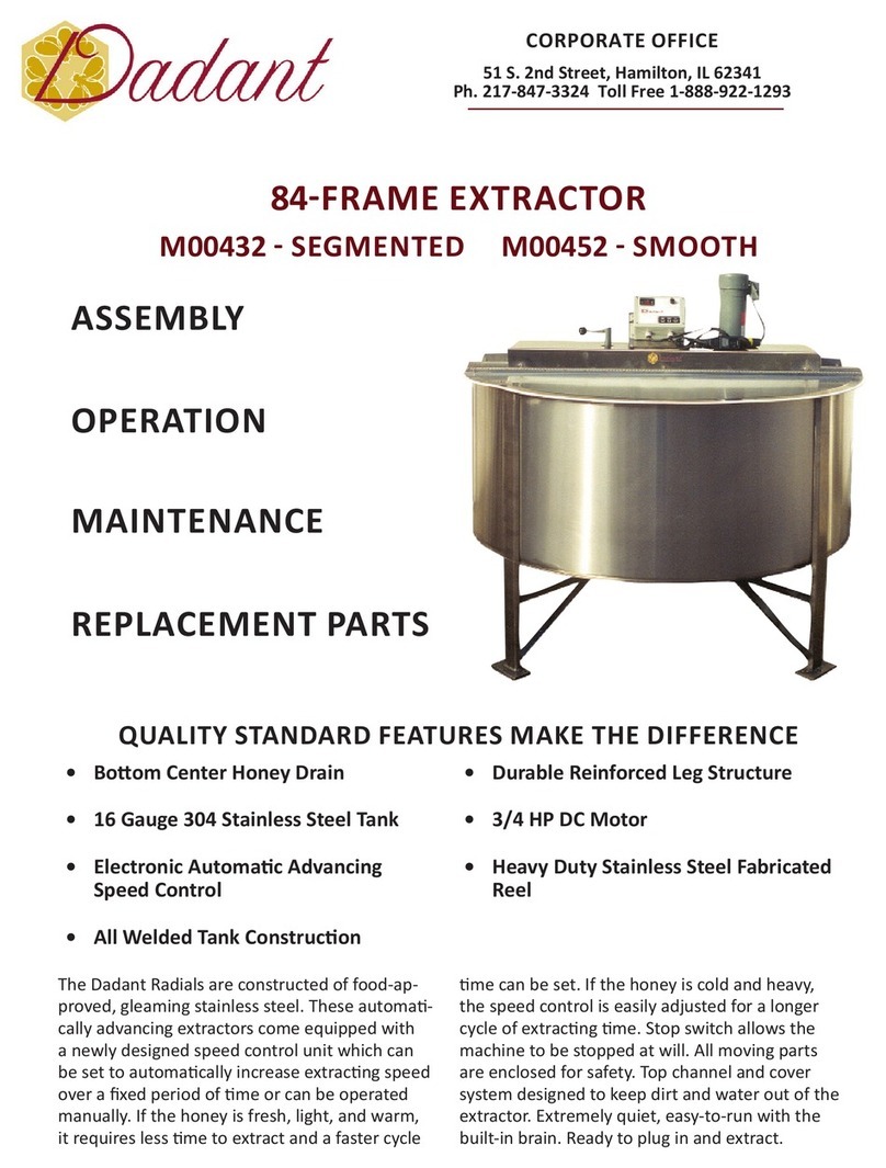
Dadant M00418 User manual

The Dadant newly re-designed 32-frame extractor now has
an integral leg system and newly designed reel
The Dadant 32-frame Radial Extractor comes completely assembled, ready to be uncrated, cleaned, and put to work. For
proper operaon, the extractor must be securely aached to the oor by all three hold-down pads – one on each leg.
The concept of the radial extractor has saved more me and more combs for beekeepers than any other invenon to reach
the industry. Radial extractors are the quickest, easiest, and most ecient way to extract honey from the comb. Uncapped
combs are placed in the circular reel like spokes of a wheel. The reel spins, creang a centrifugal force and because of the
natural upward slant of the honeycomb cells, honey is thrown from both sides of the comb at once. No further handling of
the frames is needed from starng to unloading me, freeing the operator for other work such as uncapping combs for the
next load. With radial extractors, the outward pressure is against the top bar, not against the comb surface as in small, non-
radial models, eliminang much of the breakage of the combs.
Dadant is pleased to provide you with the latest in electronic speed controls. The control on your extractor is the product
of much development and tesng and is designed for only one purpose – controlling honey extractors. Please see aached
operaonal informaon regarding the speed control.
The manual hand brake provides a posive means of slowing and stopping reel rotaon.

1. The V-belt may require adjustment or future replacement. TO ADJUST, remove the motor drive cover and loosen or
ghten the 420-34 Tension Adjustor. TO REPLACE, loosen tension adjustor and slip belt o motor pulley and 5-114
pulley.
2. The top and boom bearings will require periodic lubricaon. Always use a food-approved grease available through
your Dadant supply outlet.
3. Use cauon to avoid excessive moisture on the control and motor when cleaning the extractor aer use. If you
should experience any operaon problem with the control unit, do not try to repair the control unit yourself. Call
your nearest Dadant branch or the Hamilton home oce.
4. Keep the extractor clean between uses. Wash extractor, rinse and dry .
04-42001 1/2 HP Motor Assembly
04-42002 Brake Cover Washer
04-42003 Motor Cover Washer
04-42004 Belt Guard
04-42006 Motor Mount
04-42010 Brake Post
04-42019 Brake Band w/pin
04-42027 30-Frame Replacement Reel
04-42031 Boom Bearing Support
M00443 Electronic Speed Control
04-42034 Tension Adjustor
04-42045 Top Channel
04-42046 Hinged Cover, each half
04-42047 Replacement Tank
04-42048 Reel Sha 29”
03-50080 1-3/16” Flanged Bearing
03-50092 1-3/16” Taper Bushing
03-50103 Motor Pulley
03-50114 3-Groove Brake Pulley
03-50128 44” Belt
03-50246 Male Turnlock Connector
03-50247 Female Turnlock Connector
03-50320 Brake Post Handle
03-50328 Brake Knob

1 – – The power switch is located on the le
side of the control. This switch is used primarily at the begin-
ning and ending of the day.
2 – – The visual display lets the operator see
how the control is funconing. The display is actually 10 indi-
vidual lights. When the control is operang on automac, the
farthest le light ashes and a second-steady on-light tells the
operator visually how far the control is through its automac
cycle. This second light “marches” across the display from le
to right as the control progresses through its automac cycle.
When the automac cycle is complete, the “marching” light
returns to original posion and stays lit and the ashing light
goes o. When being operated on manual, the farthest light to
the right is a steady “on”. By watching the display and chang-
ing from automac to manual, you’ll quickly understand how
the visual display operates.
3 – – The rotary dial is used in both the automac and manual operaon. When operang the control on auto-
mac, read the outside ring to set the total me you desire your extractor to run. A 5 minutes (full clockwise rotaon) to a
30 minutes (full counterclockwise rotaon) cycle can be obtained.
When operang the control on manual, the rotary dial becomes a speed control, and the extractor will run connually at
the percent of speed the operator desires (read inner printed ring 0% to 100% speed). Cauon–Before pushing the manual
switch, be sure the rotary dial is set where you want it.
4 – 5 – 6 – – It consists of 3 switches: Auto Start (4), Manual Start (5), and Stop (6). To operate the
control on automac, press “auto start”. To operate the control on manual and adjust the speed with the rotary dial, press
“manual start”. To stop the control at any me, press “stop”.
The potenometer (right hand rotary dial) is used for both manual and automac operaons of the control. The minutes for
the automac side of the control are on the outer labeling ring (5 minutes full clockwise, 30 minutes full counterclockwise).
On manual, the percent of speed is from the very slowest (0% - full stop) full counterclockwise to maximum speed (100%)
full clockwise.
The on/o switch is mounted in the control le side panel.
A. – The control operates only on 110-120 volt A.C. Plug the power cord into an appropriate grounded
outlet and connect the yellow twist-lock connector to the connector on the extractor motor. The output of this
unit is 0 – 90 volt DC and must be used with 0 - 90 volt DC motors up to and including 1 h.p. The power cord plug
has a built-in Ground Fault Interrupter (GFI) to protect the control. On the GFI are instrucons for tesng. Please
follow those instrucons.
B. – Turn the power “on” and note that one light is lit on the “visual display.” This switch should be
shut o at the end of each extracng day, and the start-stop switches may be used between extractor loads.
C. Operator Control Center – The operator may select manual or automac operaon. To make the selecon, press
the switch for the operaon desired. On automac (auto start) the light on the le of the visual display will ash.
On manual, the light on the right of the visual display lights and stays lit while running on manual.
1. – The reel speed on manual is controlled by the dial on the upper right of the control.
For Manual Operaon, read the inside labeling. The 0-100 indicates percent of speed. 100% is approximately
280 rpm; therefore, 50% is approximately 140 rpm. To use manual, merely set the speed desired and press
manual start. The extractor will advance to the set speed and remain there. This speed may be varied at any
me during manual operaon by turning the dial.

2. – Your cycle me may be varied from 5-30 minutes. Automac operaon is obtained by
pressing auto start. The me of extractor operaon is selected by the operator. To use the automac cycle,
set the complete extracng me desired using the rotary dial. Read the outside scale (5 minutes full clockwise
to 30 minutes full counterclockwise) then press auto start. The reel will begin rotang slowly and gradually
increase speed unl full speed is reached. This occurs at 75% of the set cycle me. The reel connues at full
speed for the remainder of the cycle and automacally shuts o. The manual brake may then be used to stop
the reel.
An internal selector switch allows the owner to select a variety of automac cycles. The extractor can be precisely controlled
to allow for a variety of extracng condions (temperature—moisture level— type of honey—condion of frames). Your
control comes preset for “average’ operang condions for your size extractor and will be the proper seng for 80 -
90% of extracng condions. . However, for your parcular
extracng job, a dierent operaon characterisc may be desired.
To select a dierent operang characterisc, loosen the four sloed head screws holding the cover in place. Be sure the
control is unplugged from its Power Source. Li the front cover up about 2 inches and unhook the 4-wire connector and the
3-wire connector. On the printed circuit board is a small selector switch with an arrow and a screwdriver slot just le of the
3- and 4-wire connectors. Around the outer edge, the leers A-F and the numbers 0-9 appear. The arrow will be poinng
at one of these characters. By referring to the charts below, you may select an operang characterisc just right for your
extracng condions. For assistance, call your local Dadant Branch Manager.
For “average” operaon, the selector switch is set on “B” for a 30-frame, on “E” for a 60-frame, and on “D” for a Honey
Master. (The larger the extractor, the slower the acceleraon and starng and ending speeds).
Example 1—A Honey Master being used to extract colder heavier honey might be “throwing” some combs on a “D” seng.
Since slower acceleraon is indicated “6” would be a proper selecon. An “A” could also be a good choice in order to slow
both acceleraon and top speed.
Example 2—a 30-frame extractor being used to extract warm, light honey might be “too slow” extracng or not drying
combs suciently. An “8” would be a good alternate selecon—faster acceleraon.
Table of contents
Other Dadant Scrubber manuals
Popular Scrubber manuals by other brands

Wassermann Dental-Maschinen
Wassermann Dental-Maschinen SG-1 user manual

Amperes Electronics
Amperes Electronics iPX5455 instruction manual

HAL Extraction
HAL Extraction 85U Safety and operating manual

Magnitone
Magnitone SCRUB UP manual

Minuteman
Minuteman PORT A SCRUB Instruction manual / spare parts list

KENT
KENT SelectScrub 20 Instructions for use

DiamaPro Systems
DiamaPro Systems AS-500 owner's manual

Tennant
Tennant EC H2O M20 Operator's manual

Windsor
Windsor Chariot 3 iScrub 26 CS26 operating instructions

Caple
Caple QCH1 Installation and operating instruction booklet

PowerPoint
PowerPoint P21350XBSS Use and maintenance

Tennant
Tennant Nobles T350 Operator's manual