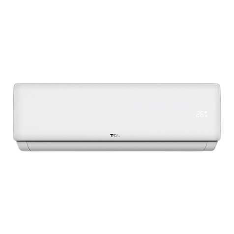
DAEWOO ELECTRONICS DSB-300L User manual

Service Manual
Split System
Air Conditioner
Model: DSB-300L
DSB-300LH
S/M NO : DSB300LH001
Aug., 2005
✔Caution
: In this Manual, some parts can be changed for improving,
their performance without notice in the parts list. So, if you
need the latest parts information, please refer to PPL(Parts
Price List) in Service Information Center

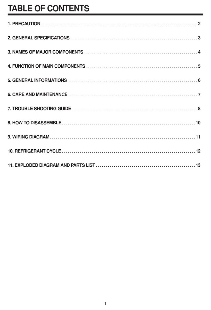
CONTENTS
1. FEATURES................................................................................................................2
2. SPECIFICATIONS.....................................................................................................4
3. OUTLINE AND DIMENSIONS.................................................................................5
4. REFRIGERATION CYCLE DIAGRAM ....................................................................6
5. OPERATION LIMITS.................................................................................................8
6. WIRING DIAGRAM...................................................................................................9
7. TROUBLESHOOTING............................................................................................13
8. ELECTRONIC CONTROL .....................................................................................14
9. EXPLODED VIEW PARTS.....................................................................................20
Contents

2
1
FEATURES
1.1 The evaporator employs a 2-bend structure which enlarges the heat exchange surface.
1.2 With three grilles, the outlet frame and the base plate are integrally designed and of easy
installation.
1.3 The front panel is tightly fixed with the front frame by simply buckling the latter with a buckle
mechanism on the panel.
1.4 The manual force switch employs comfortable switch push buttons.
1.5 Large diameter, 2-segment cross flow fan is installed, with wider air outlet, well-distributed air
and low noise.

3
DAEWOO MODEL DSB-300L DSB-300LH
Power supply Ph-V-Hz 220V,50HZ 220,50HZ
Cooling Capacity Btu/h 28000 28000
Input W 3150 3130
Rated current A 14.2 14.1
EER Btu/w.h 8.9 8.9
Heating Capacity Btu/h 31000
Input W 3150
Rated current A 14.2
COP Btu/w.h 9.8
Moisture Removal L/h 2.5 2.5
Max. input consumption W 3840 3880
Max. Current A 18.5 19
Starting current A 80 80
Compressor Model QP442PBA QP442PBA
Type Rotary Rotary
Brand LG LG
Capacity Btu/h 26000 26000
Input W 2574 2574
Rated current(RLA) A 12.5 12.5
Locked rotor Amp(LRA) A NOT FIXED NOT FIXED
Thermal protector Internal Internal
Capacitor uF 55 55
Refrigerant oil ml 700 700
Indoor fan motor Model YDK32-4 YDK32-4
Brand Welling Welling
Input W 52/46/42 52/46/42
Capacitor uF 2.5/450V 2.5/450V
Speed(hi/mi/lo) r/min 1350/1220/1100 1350/1220/1100
Indoor coil a. Number of rows 2 2
b. Tube pitch(a)x row pitch(b) mm 25.4X22 25.4X22
c. Fin spacing mm 1.3 1.3
d. Fin type (code) Hydrophilic aluminium Hydrophilic aluminium
e. Tube outside dia.and type mm Ø9.53,innergroove tube Ø9.53,innergroove tube
f. Coil length x height x width mm 906X279X44 906X279X44
g. Number of circuits 3 3
2
SPECIFICATIONS

4
DAEWOO MODEL DSB-300L DSB-300LH
Indoor air flow (Hi/Mi/Lo) m3/h 1050/950/855 1050/950/855
Indoor noise level (Hi/Mi/Lo) dB(A) 48/45/42 48/45/42
Indoor unit Dimension (W*H*D) mm 1190X320X205 1190X320X205
Packing (W*H*D) mm 1265X445X320 1265X445X320
Net/Gross weight Kg 20/25 20/25
Outdoor fan motor Model YDK100-6D YDK100-6D
Brand Welling Welling
Input W 173 173
Capacitor uF 5 5
Speed r/min 900 900
Outdoor coil a. Number of rows 2 2
b. Tube pitch(a)x row pitch(b) mm 25.4x22 25.4x22
c. Fin spacing mm 1.4 1.4
d. Fin type (code) Unhydrophilic aluminium Hydrophilic aluminium
e. Tube outside dia.and type mm Ø9.53,innergroove tube Ø9.53,innergroove tube
f. Coil length x height x width mm 775X660X44 775X660X44
g. Number of circuits 4 4
Outdoor air flow m3/h 2500 2500
Outdoor noise level dB(A) 62 62
Outdoor unit Dimension(W*H*D) mm 845X695X335 845X695X335
Packing (W*H*D) mm 965X770X395 965X770X395
Net/Gross weight Kg 60/65 62/67
Refrigerant type g R22/2360 R22/2380
Design pressure MPa 2.6 2.6
Refrigerant piping Liquid side/ Gas side mm(inch) Ø9.53 / Ø16.0 Ø9.53 / Ø16.0
Max. refrigerant pipe length m 15 15
Max. difference in level m 8 8
Connection wiring No No
Plug type No No
Thermostat type Electronic control Electronic control
Operation temp °C 17-30 17-30
Ambient temp °C 18-56 -7 - 56
Application area m2 50~68 50~68
Qty’per 20’ / 40’ / 40’HQ set 59/127/136 59/127/136
Remark(alternate compressor)

5
3
OUTLINE AND DIMENSIONS

◆Heating and cooling(DSB-300LH)
6
4
Refrigeration cycle diagram

7
◆Cooling only(DSB-300L)

8
◆Cooling operation
5
Operation limits
Note : The chart is the result from the continuous operation under constant air temperature conditions.
However, excludes the initial pull-down stage.
◆Heating operation
Note : The chart is the result from the continuous operation under constant air temperature conditions.
However, excludes the initial pull-down stage.

6
WIRING DIAGRAM
DSB-300L Indoor Unit

10
DSB-300L Outdoor Unit

11
DSB-300LH Indoor Unit

12
DSB-300LH Outdoor Unit

13
7
TROUBLESHOOTING
LED status
Operation indicator, time indicator, Defrosting
indicator (fan indicator, for cooling only type)auto
indicator flicker at 5Hz
Time indicator flickers at 5Hz
Operation indicator flickers at 5Hz
Defrosting indicator flickers at 5Hz
Defrosting indicator, auto indicator flicker at 5Hz
Auto indicator, indicator flicker at 5Hz
Four times Current protection (PRCUR1) 5Hz
the room temperature sensor o is open or short
the evaporator temperature sensor is open or
short
the condenser temperature sensor is open or
short
Outdoor unit protects(Outdoor temp, sensor,
phase order etc)
EEROM Communication error

14
8
ELECTRONIC CONTROL
8.1 Fan only mode
Fan speed is high/mid/low/ Auto
8.2 Cooling mode
The 4-way valve is closed at cooling mode.
The action of the compressor and the outdoor fan:
T: Room temp.
Ts: Setting temp.
Auto fan
Anti-freezing control to indoor evaporator
Condenser high temp. protection( only for heat pump)
Condition Compressor Outdoor fan
Temp. up T> Ts+1 On On
T<Ts+1 Off Off
Temp. down T> Ts On On
T<Ts Off Off
Temp. Condition Compressor
Temp. up T> TE10 Off
T< TE10 On
Temp. down T> TE11 Off
T< TE11 On
Condition Compressor Outdoor fan
Temp. Time
Temp. up T> TE6 On On
T< TE6 >4 Minutes Off Off
Temp. down T> TE5 On On
T< TE5 >4 Minutes Off Off
Condition(T=Indoor Temp.-Setting Temp.) Indoor fan speed
Temp. up T<1°C Low
1°C<T<4°C Med.
T>5°C High
Temp. down T> 4°C High
1°C<T<4°C Med.
T<1°C Low

15
8.3 Dehumidifying mode
8.3.1 Indoor fan speed at low speed.
8.3.2 Protection is same as cooling mode.
8.4 Heating mode
8.4.1 Generally, the 4-way valve is open in heating mode, but it is closed in defrosting mode.
8.4.2 Generally, the outdoor fan is turned off with the on-off action of compressor in heating
mode, except for the defrosting mode or the end of defrost.
8.4.3 Action conditions of compressor at heating mode: compressor must run for 4 minutes after
starting and then judge temperature. Meanwhile other protections are still valid.
8.4.4 Indoor Fan actions at heating mode
Indoor Fan can be set at HIGH/MID/LOW/AUTO by using a remote controller,
Anti-cold wind function 1.
Anti- cold air protection 2 ( when the room temp. satisfy the setting temp.)
Condition Compressor Outdoor fan
Room temp. up T> Ts+4 Off Off
T<Ts+4 On On
Room temp. down T< Ts+3 On On
T>Ts+3 Off Off
Condition Indoor fan speed
T= Indoor exchanger temp.
Indoor exchanger T<TE1 Off
temp. up TE1<T<TE2 Low speed
T>TE2 Setting fan speed
Indoor exchanger T>TE3 Setting fan speed
temp. down TE4<T<TE3 Low speed
T>TE4 Off
T=evaporator pipe sensor temp. Indoor fan speed
Room temp. up T<TE14+2_ Low speed or stop
T> TE14+2_ Setting speed.
Room temp. down T> TE14 Setting speed.
T< TE14 Stop after 15 seconds Low speed

16
Auto wind
Indoor evaporator high-temperature protection
Condition Indoor fan speed
T=Indoor Temp. -Setting Temp.
Room temp. up T<2_ Med. speed
T>2_ Low speed.
Room temp. down T> 0_ Low speed.
T<0_ Med. speed
Condition Compressor Outdoor fan
T= Indoor exchanger temp.
Indoor exchanger T<TE8 On On
temp. up TE8<T<TE7 On Off
T>TE7 Off Off
Indoor exchanger T>TE9 Off Off
temp. down T<TE9 On On
8.5 Defrosting mode
8.5.1 Conditions of defrost:
Defrosting starts when either of the following : T3 lower than 0°c, lasts for more than 40
minutes, provided that the time period when the temperature is lower than -3°c
consecutively reaches 3 minutes.
Calculate from the end of latest defrost, evaporator high temp. protection only closes
outdoor fan with the compressor still running. Add up to 90 minutes
.8.5.2 Conditions of defrost ending:
Defrosting ends when either of the following :
The time gets to 10 minutes;
T3>20°c

17
8.6 Auto mode
8.6.1 When running in automatic mode, the air conditioner automatically selects one of the
following operation modes: cooling, heating or ventilation according to the difference
between room temp. (TA) and set temp. (TS).
8.7 Economic mode
Cooling: The set temperature rise 1°C per hour. Two hours later, the set temperature will
maintain as a constant and the air circulation is kept at low speed.
Heating: The set temperature decrease 1°C per hour. Two hours later, the set temperature will
maintain as a constant and the air circulation is kept at low speed (Cold air proof
function takes priority over all).
8.6.2 At auto mode, the indoor fan blows automatically in selected mode.
8.6.3 One mode should be carried out for at least 15 minutes once selected. If the compressor
cannot start for 15 minutes, reselect the operation mode according to the room temp. and
set temp., or reselect when the setting temp. changed
8.5.3 Time sequence of the whole defrosting procedure is as follows:
Remark: when the evaporator pipe sensor temp. more than TE16, The indoor fan start to run.
TA—TS Operation mode
TA—TS>2°C Cooling
-1°C≤TA—TS≤+2°C Air-only
TA—TS<-1°C Heating (air-only for cooling only type)

18
8.8 Manual operation
Manual operation is controlled by touching buttons and divided into force cooling and forced auto
mode. It transfers between these two modes by pressing the buttons, the cycling order of the
button press is:
8.8.1 Forced Cooling
8.8.1.1 In forced cooling mode, the remote signal is not accepted.
8.8.1.2 The compressor is unconditionally turned on, after 30 minutes cooling operation whose
fan mode is set as low, the A/C operates in the forced auto mode under the
requirements of the forced auto mode.
8.8.1.3 During the start-up and operation, all of the following protecting functions work:
3minutes start-up delay protection, overload protection, outdoor protection, evaporator
Protection against low temperature. If any of the protection functions, the comparative
protecting action is executed.
The forced cooling mode is closed by one touch on the button, meanwhile the operation
light is off, the buzzer buzzes lasts for 1 seconds, then A/C turns to be closedown
status.
8.8.2. Forced Auto
8.8.2.1 Remote control signal can be received in forced auto mode. When receiving the
signals, the forced auto mode will be canceled and the A/C changes to remote control
status and performs operation as the signals indicates.
8.8.2.2 The system performs control according to the remote control auto mode with a set
temperature of 24°C.
8.9 Timer
24 hours timer on or off.
8.10 Protecting Function
8.10.1 Compress with a delay of 3 minutes.
8.10.2 Sensor open and break protection
8.10.3 EEROM error protection.
8.10.4 Current protection function.
Remote mode Forced auto Forced cooling

19
8.11 Auto restart Function
In case of a sudden power failure, this function automatically sets the unit to previous settings
before the power failure when power returns.
8.12 Models and Parameters
Condition Indoor fan
Compressor Outdoor fan
Remark
Current up I< IRESTORE On On On
IRESTORE <I< IFAN On On Off Heating mode
Low speed On On Cooling mode
IFAN <I<I5MIN Off Off After 5 Minutes
I5MIN<I< I3SEC Off Off After 3 Seconds
Current down
I5MIN<I< I3SEC Off Off After 3 Seconds
IFAN <I<I5MIN Off Off After 5 Minutes
IRESTORE <I< IFAN On On Off Heating mode
Low speed On On Cooling mode
I< IRESTORE On On On
Model DSB-300L DSB-300LH
I3SEC 24A 24A
I5MIN 22A 22A
IFAN 18A 18A
IRESTORE 16A 16A
TE1 25°C
TE2 32°C
TE3 30°C
TE4 20°C
TE5 2°C 2°C
TE6 12°C 12°C
TE7 63°C 63°C
TE8 54°C 54°C
TE9 50°C 50°C
TE10 72°C 72°C
TE11 68°C 68°C
TE14 32°C 32°C
TE16 42°C 42°C
This manual suits for next models
1
Table of contents
Other DAEWOO ELECTRONICS Air Conditioner manuals