DAEWOO ELECTRONICS DSA-240L-R User manual

Manual de Servicio
Acondicionador de Aire Tipo Split
Modelo: DSA-240L-R

CONTENTS
1. Specifications..........................................................................................................2
2. Outline and Dimensions.........................................................................................4
3. Operation.................................................................................................................6
4. Wiring Diagram.....................................................................................................17
5. Refrigerant Cycle..................................................................................................20
6. Control Block Diagram .........................................................................................21
7. Electric Circuit Diagram........................................................................................23
8. Trouble Shooting...................................................................................................26
9. Key Components of Electronic Circuit.................................................................48
10. Disassembly Instructions .....................................................................................51
1) Indoor Unit........................................................................................................51
2) Outdoor Unit.....................................................................................................52
3) Exploded Diagram (Indoor Unit)......................................................................53
4) Exploded Diagram (Outdoor Unit)...................................................................56
5) Control Box Assembly......................................................................................60
Contents

2
1. SPECIFICATIONS
MODEL DSA-240L-R
ITEM
Function Cooling
Class T
Power AC 220V/ 60Hz
Capacity W 7,030
Btu/h 24,000
Dehumidification l/h 3.2
Running Current A 11.7
Power Input W 2,500
Type Recipro
Model AWG5530EXC
Capacitor 45µF/ 400VAC
Division Indoor Unit Outdoor Unit
Type Cross flow fan Propeller fan
Capacitor 2µF 400VAC 5µF 400VAC
Motor Model Number IC9430DWKG7A 05ME986DERC
Control Capillary
Charge Q'ty g 2,100
Type Flare
OD
(Liquid/Suction)
in(mm) 3/8 (9.52) 5/8 (15.9)
Dimensions (W x H x D) mm 1080 x 298 x 200 872 x 675 x 325
Net Weight kg 14.7 64
Electrical
Data
Compressor
Fan
Motor
Refrigerant
(R-22)
Connection
* DSA-240L-R

3
MODEL DSA-240LH-R
ITEM
Function Cooling & Heating
Class T
Power AC 220V/ 60Hz
Capacity W 7,030
Btu/h 24,000
Dehumidification l/h 2.67
Running Current A 11.5 / 11.8
Power Input W 2,500 / 2,550
Type Recipro
Model AWG5530EXC
Capacitor 45µF/ 400VAC
Division Indoor Unit Outdoor Unit
Type Cross flow fan Propeller fan
Capacitor 2µF 400VAC 5µF 400VAC
Motor Model Number IC9430DWKG7A 05ME986DERC
Control Capillary
Charge Q'ty g 2,200
Type Flare
OD
(Liquid/Suction)
in(mm) 3/8 (9.52) 5/8 (15.9)
Dimensions (W x H x D) mm 1080 x 298 x 200 872 x 675 x 325
Net Weight kg 14.7 64
Electrical
Data
Compressor
Fan
Motor
Refrigerant
(R-22)
Connection
* DSA-240LH-R
4
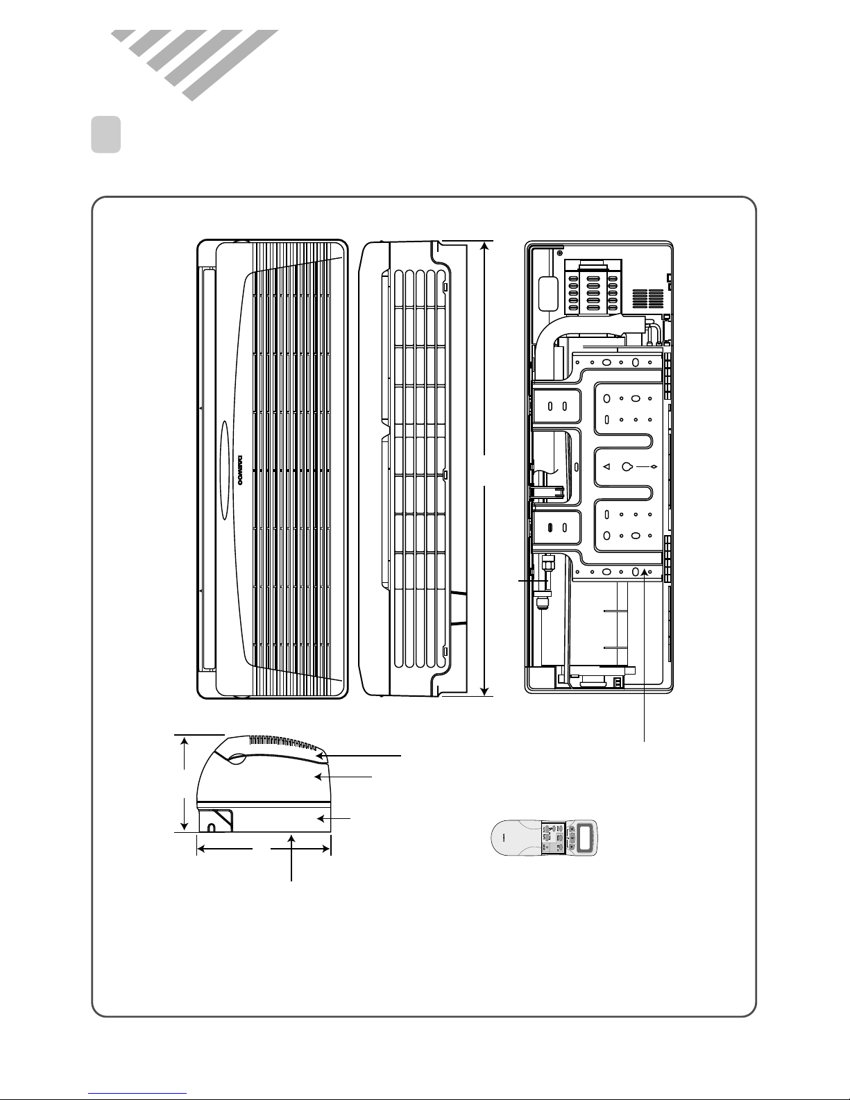
750
Plate Mounting
REMOCON
Connecting Pipe
Grille Insert
174
245
REMOTECONTROLLER
Frame Grille
Body
Plate Mounting
2. OUTLINE AND DIMENSIONS
1
INDOOR UNIT
* DSA-240L-R/LH-R

5
Inlet
380
699
323
foot
Service valve
873
Cabinet front Service Cover
Cabinet Side
* DSA-240L-R/LH-R
2
OUTDOOR UNIT
6
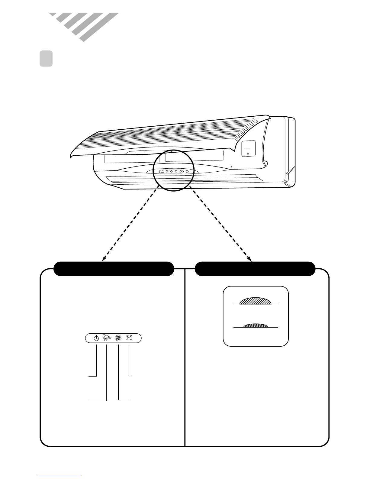
1
PARTS OF NAME AND FUNCTION
3. OPERATION
* DSA-240L-R/LH-R
■
Remote Control Signal Receiver
This place is the part to receive the signal if it
receive the signal, you can hear the signal “beep.
“beep, beep.”
■
There is a switch panel at inside of
Front Panel. At the time of operating,
open the Front Panel.
Emergency switch can be used when the remote
controller is lost or Testing.
Remote switch is usually used by remote
controller.
Indoor Unit Display Switch Panel
Timer (Yellow)
Lights-on during the time
of reservation mode.
Quick (Red)
Lights-on during the time
of Quick Mode.
ON (Red)
Lights-on
during the operation
Air clean (Green)
Lights-on
during the operation
EMERGENCY
REMOCON
REMOCON
EMERGENCY
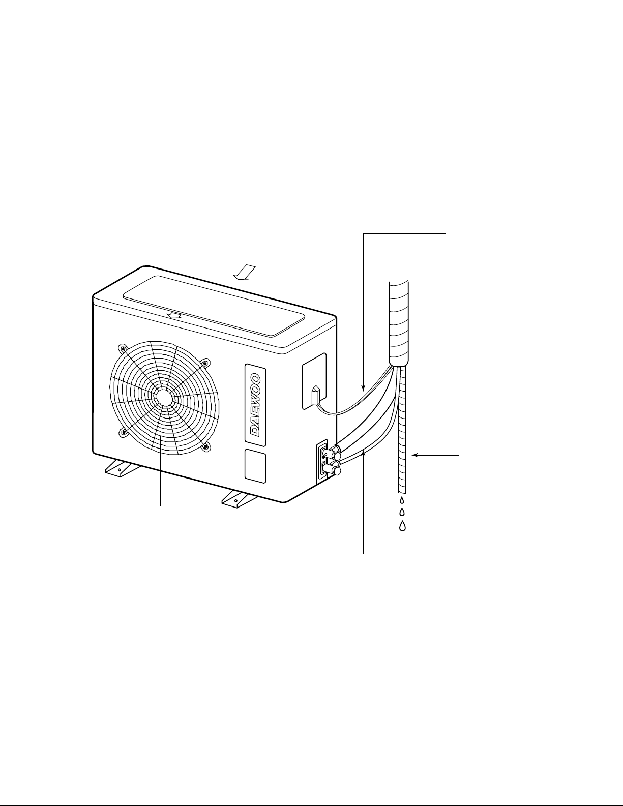
7
* DSA-240L-R/LH-R
Air Inlet
Air Outlet
Connection Pipe
Connection wire
Drain Hose
8
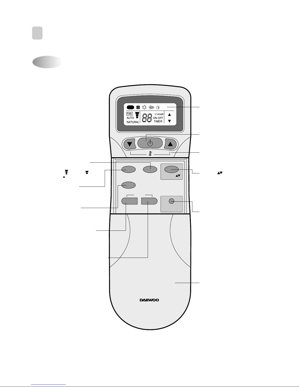
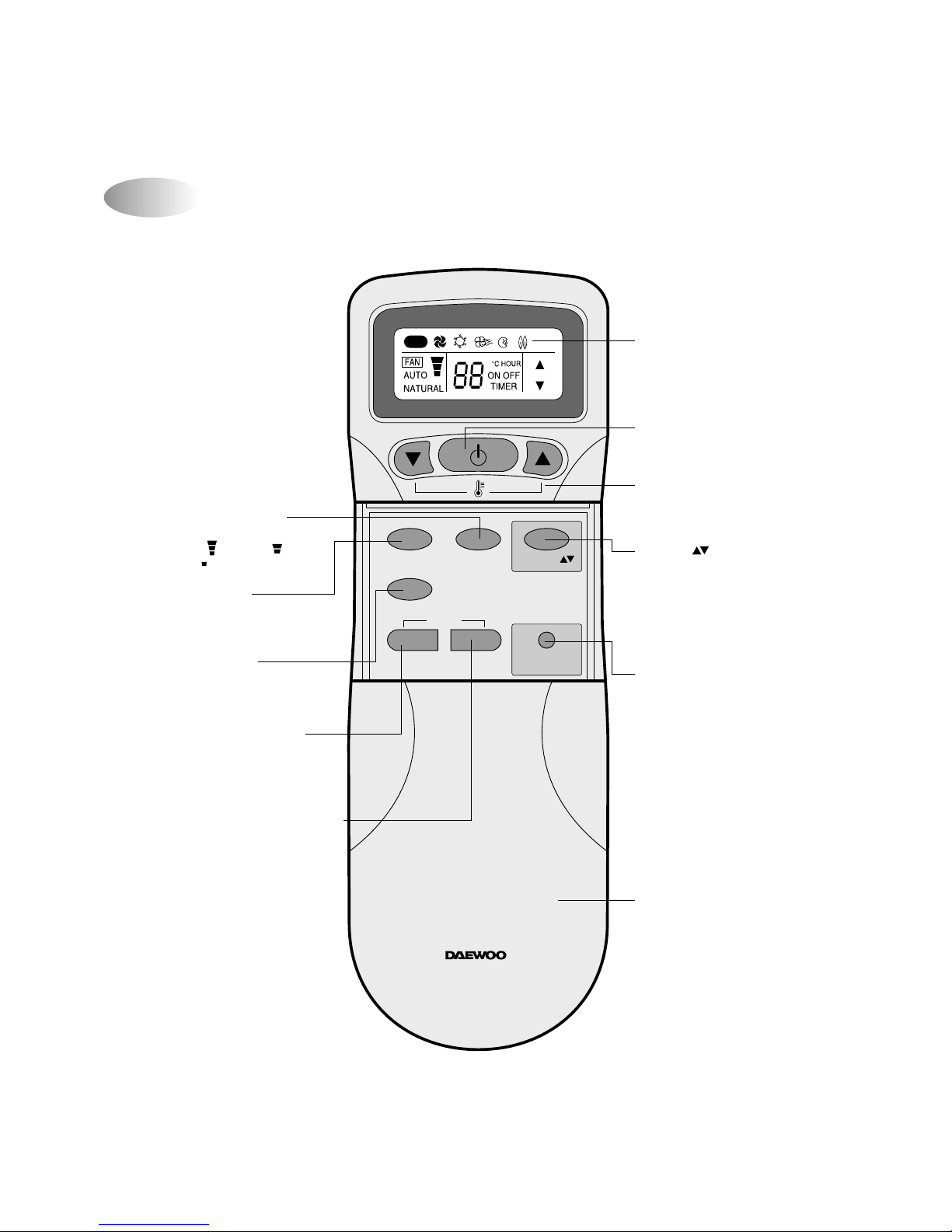
Name of Each Button
2
REMOTE CONTROLLER
* DSA-240L-R
MODE
SLEEP
ON/OFF
TIMER
ENTER/
CANCEL
FAN SPEED
TURBO/MILD
Display
Displays information
pertaining to unit.
TURBO/MILD
Press to be colder the unit.
TIMER ENTER/CANCEL Button
Press to enter a timer setting or
to cancel timer setting
TIMER ON/OFF Button
Press to set the unit of or on time.
(0.5, 1, 1.5, 2, 2.5, 3, 4, 5, 6, 8,
10, 12, 16, 20, 24hr)
MODE Button
Press to cycle through the modes
(Auto/Quick/Cooling/Fan/Dry)
SLEEP Button
Press to set the unit for
the sleep mode.
FAN DIR.
FAN DIR. Button
Press to select up/down
direction for fan.
ON/OFF Button
Press to turn the unit
on or off.
TEMPERATURE Buttons
Press to raise or lower
the desired temperature.
FAN SPEED Button
Press to select the fan speed
(High " ", Middle " ",
Low " ").
COVER
Slide down to access most
of the remote buttons.
Slide down further to
access the battery
compartment.
AUTO
REMOTE CONTROLLER
9
Name of Each Button
* DSA-240LH-R
MODE
SLEEP
ON/OFF
TIMER
ENTER/
CANCEL
FAN SPEED
TURBO/MILD
Display
Displays information
pertaining to unit.
TURBO/MILD
Press to be colder the unit.
TIMER ENTER/CANCEL Button
Press to enter a timer setting or
to cancel timer setting
TIMER ON/OFF Button
Press to set the unit of or on time.
(0.5, 1, 1.5, 2, 2.5, 3, 4, 5, 6, 8,
10, 12, 16, 20, 24hr)
MODE Button
Press to cycle through the modes
(Auto/Quick/Cooling/Fan/Dry)
SLEEP Button
Press to set the unit for
the sleep mode.
FAN DIR.
FAN DIR. Button
Press to select up/down
direction for fan.
ON/OFF Button
Press to turn the unit
on or off.
TEMPERATURE Buttons
Press to raise or lower
the desired temperature.
FAN SPEED Button
Press to select the fan speed
(High " ", Middle " ",
Low " ").
COVER
Slide down to access most
of the remote buttons.
Slide down further to
access the battery
compartment.
AUTO
REMOTE CONTROLLER
Table of contents
Other DAEWOO ELECTRONICS Air Conditioner manuals


Popular Air Conditioner manuals by other brands


CIAT
CIAT Magister 2 Series Installation, Operation, Commissioning, Maintenance

Bestron
Bestron AAC6000 instruction manual

Frigidaire
Frigidaire FFRE0533S1E0 Use & care guide

Samsung
Samsung AS09HM3N user manual

Frigidaire
Frigidaire CRA073PU11 use & care

Soleus Air
Soleus Air GB-PAC-08E4 operating instructions

McQuay
McQuay MCK020A Technical manual

Webasto
Webasto Frigo Top 25 DS Instructions for use

Frigidaire
Frigidaire FAZ12ES2A installation instructions

Mitsubishi Electric
Mitsubishi Electric MSC-GE20VB operating instructions

Mitsubishi Electric
Mitsubishi Electric PLA-M100EA installation manual

Daikin
Daikin Split Sensira R32 Service manual