DAEWOO ELECTRONICS DWA-180C User manual

1
TABLE OF CONTENTS
1. PRECAUTION...............................................................................2
2. GENERAL SPECIFICATIONS ................................................................3
3. NAMES OF MAJOR COMPONENTS .........................................................4
4. FUNCTION OF MAIN COMPONENTS ........................................................5
5. GENERAL INFORMATIONS .................................................................6
6. CARE AND MAINTENANCE .................................................................7
7. TROUBLE SHOOTING GUIDE ...............................................................8
8. HOW TO DISASSEMBLE...................................................................10
9. WIRING DIAGRAM.........................................................................11
10. REFRIGERANT CYCLE ...................................................................12
11. EXPLODED DIAGRAM AND PARTS LIST ..................................................13

2
1. PRECAUTION
Please observe the following instructions.
1. Turn off unit.
Make sure the unit is OFF and the AC cord is unplugged before repairing or servicing.
2. In case of checking the circuit unavoidably while the unit is connected with power source, be careful
not to connect with the part of electric charge.
You may cause electric shock.
3. Use of proper part if you need to replace the part, be sure to use genuine part of servicing model.
Do not repair or replace the electric contact part.
Consumer must not repair the unit, because it is dangerous.
4. Use of proper tool.
You must use the proper tool to repair the unit, and use the measuring appliance adjusted accurately.
5. Damage of electric wire and power cord when servicing.
Check electric wire and a surely replace a damage electric wire and a damage power cord.
6. Never use connecting the middle of wire, after cutting the middle of wire.
It may cause a fire and trouble.
7. Checking the insulation resistance.
After you complete the assembly of unit, surely check the insulation resistance.
Confirm that the insulation resistance of the power line and the ground terminal is over 30MΩby measuring insulation
resistance.
8. Checking the ground.
After checking the ground, servicing it completely.
9. Checking the installation.
After checking the installation, servicing it completely.
10. Care children.
When servicing, do not make the children approach the air-conditioner.

3
2. GENERAL SPECIFICATIONS
ITEM MODEL DWA-180C
Power Source V/Hz AC 220V/60Hz
Cooling Capacity Btu/h 17,500
Kcal/h 4,410
Energy Efficiency Ratio Btu/wh 9.0
Kcal/wh 2.3
Dehumidification L/h 2.0
Electrical Data Power Input(W) 1,900
Running Current(A) 9.0
Compressor
Type Rotary
Model QJ250KD24A
Capacitor AC 400V, 30µF
Model IC-12640DWWF6A
Fan Motor Capacitor AC 400V, 6µF
Indoor-Fan Blower Fan
Outdoor-Fan Propeller Fan
Refrigerant(R-22) Control Capillary
Charge Amount (g) 970g
Dimensions Unit (W x H x D) 660 x 430 x 705 (mm)
Packing (W x H x D) 711 x 525 x 757 (mm)
Weight Net Weight (Kg) 52.5
Gross Weight (kg) 57.5

4
3.NAMES OF MAJOR COMPONENTS
NO PART NAME
1 AIR FILTER
2 GRILLE FRONT
3 CABINET
4 BLADE VERTICAL
5 KNOB THERMOSTAT
6 KNOB SELECTOR
NO PART NAME
7 BLADE HORIZONTAL
8 AIR VENT
9 AIR INTAKE
10 AIR DISCHARGE
11 AUTO SWING SWITCH
3
9
0
7
4
8
q
1256

5
4. FUNCTION OF MAIN COMPONENTS
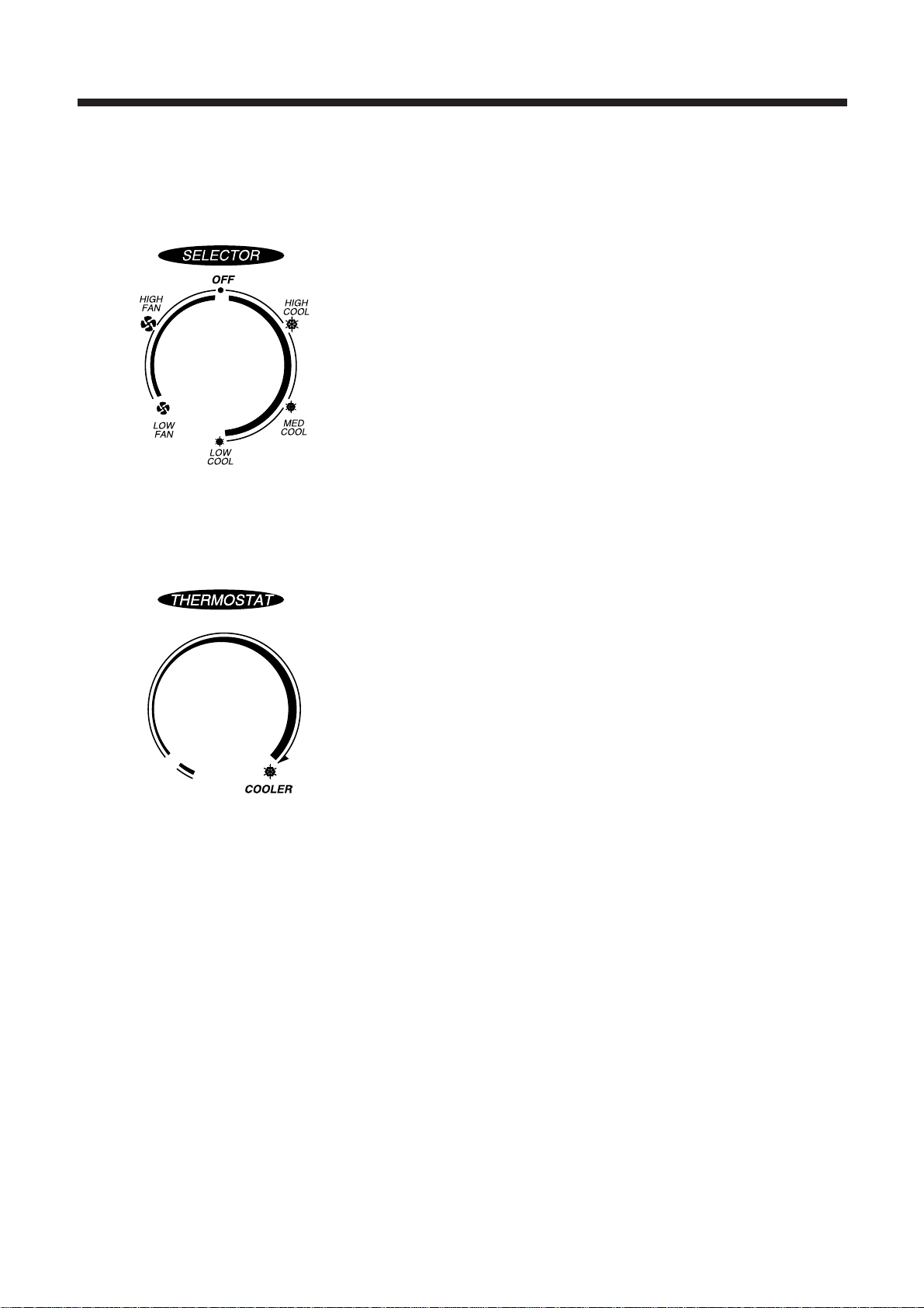
1. ROTARY SWITCH (SELECTOR)
Please refer to the part of selector in the chapter 9 (Wiring Diagram).
The rotary switch (selector) controls the fan motor’s rotation speed, and has six positions.
The function of the six position is as follow.
¡
OFF: This position stops all operations of the air conditioner.
¡
HIGH COOL: This position provides the maximum air flow for rapid
cooling, dehumidifying and dust removing operations.
(Use this position on sultry summer days.)
¡
MED COOL: This position provide the medium air flow for cooling
dehumidifying and dust removing operations
¡
LOW COOL: This position provides the minimum air flow for quiet
cooling, dehumidifying operations.
(Use this position on suitable for night-time.)
¡
HIGH FAN: This position provides the maximum air fiow alone fan
operation without cooling operation.
¡
LOW FAN: This position provides the minimum air flow air flow alone
fan operation without cooling operation.
2. THERMOSTAT (TEMPERATURE CONTROL)
¡
The Thermostat automatically starts and stops operation in order to keep
the room temperature at a proper level, and this results in efficient use of
power and economical cooling.
¡
Turn clockwise for a cooler room temperature.
¡
Turn counter-clockwise for a warmer room temperature.
3. MOTOR
The motor is used to rotate the indoor and outdoor fan so that the room air can be recirculated.
4. FAN
¡
BLOWER FAN: The Blower draws hot air from the room through the Evaporator and then discharges it back into the
cool air. It circulates the room air.
¡
PROPELLER FAN: The propeller draws outdoor air through louvering and cools Condenser, and then blows the hot
air out.
5. CAPACITOR
The Capacitor enlarges the difference of phase between main coil and sub coil so that the Compressor and Fan Motor
starts well.
6. ACCUMULATOR
The Accumulator blocks the unflow of liquid refrigerant and impurities into the Compressor.

6
5. GENERAL INFORMATIONS
1. CHANGING AIR FLOW DIRECTION
Air flow deflectors divert air from center flow to left or right.
Adjust deflectors for desired air flow pattern.
2. AIR FLOW AROUND UNIT
Check in door grill and outdoor louvers for air flow obstructions. Do not block air flow to and from unit. The outdoor coil
should be checked and periodically cleaned for debris that may collect and block unit air flow. If air flow is obstructed
or deflected back into unit, the compressor may cycle on and off rapidly, causing early compressor failure.
3. Electrical Grounding Instructions.
This appliance is equipped with a three-prong(grounding) plug for protection against possible shock hazards. If a two-
prong wall receptacle is encountered, the customer is required to contact a qualified electrician and have the two-
prong wall receptacle replaced with a properly grounded three-prong wall receptacle in accordance with the National
Electrical Code.
4. USE OF EXTENSION CORDS
Because of potential safety hazards under certain conditions we strongly recommend against the use of an extension
cord. However, if you still elect to use an extension cord, it is absolutely necessary that it be a UL listed 3-wire
grounding type appliance extension cord rated has a 3-blade grounding plug and a 3-slot receptacle that will plug into
appliance. The marked rating of the extension cord should be AWG #12 or more.
5. DRAIN HOLE AND WATER DRIPPING OUTSIDE
Locate drain hole at the rear of unit. Water in base pan is picked up by the fan blade and thrown onto the warm
outdoor coil where it evaporates. The air conditioner must be installed level or tited or slightly to the outside for proper
water disposal. On exceptionally hot and humid days the air conditioner may permit excess water to pass thru rear
drain hole or overflow. This should be considered normal.

7
6. CARE AND MAINTENANCE
1. AIR FILTER
Clean the air filter, which removes dust inside the room.
It should be washed at least once every week during operation.
1. Remove the Air Filter from the front grill by pulling up.
2. Clean Air Filter with a vacuum cleaner or lukewarm, soapy water.
3. Shake it when clean to remove moisture completely. Replace it.
2. CLEANING THE AIR CONDITIONER
1. At least once a year, remove cabinet and thoroughly clean air conditioner. Have the unit inspected by an authorized
servicer to ensure unit is functioning properly.
2. Wash air conditioner with lukewarm, soapy water as needed. Rinse and dry thoroughly.
3. If using concentrated liquid detergent, dilute in warm water first.
4. Front grill may be wiped off with a cloth dampened in a mild detergent solution.
5. Cabinet may be washed with mild soap or detergent and lukewarm water, then polished with liquid wax for
appliances.
6. Condenser and Evaporator coils should be cleaned at the beginning of each cooling season. Use a soft brush or
vacuum cleaner to clean them, making sure that the Condenser and Evaporator coils are not damaged.
7. Do not use abrasive cleaners. These items scratch, crack and discolor surfaces.

8
7. TROUBLE SHOOTING GUIDE
TROUBLE SITUATION ANALYSIS CAUSE REMEDY
Fan motor and
compressor do not run
Switch is in “cool”
position but the
compressor does not
run
1. Power failure
2. Power is supplied,
but the equipment
does not run
1. Not operating at all
2. Compressor
3. Frequent start and
stop
1) Power plug
2) Circuit breaker
1) receptacle
2) Operation switch
3) Cord or lead wire to
the switch
1) Compressor
2) Thermostat
3) Selector switch
4) O.L.P
5) Capacitor
1) Electricity
2) Room temperature
and outside
temperature
3) Compressor
4) O.L.P
5) Capacitor
1) Thermostat
2) Capacitor
3) O.L.P
1) Power failure
2) Circuit breaker is tripped
3) Power plug is not contacting
¡Disconnection
¡Mechanical failure of switch
1) Disconnection
2) Malfunction of contact
¡Disconnection or burned-out
1) Failure
2) Malfunction
3) Knob is not set to the proper
setting
¡Failure of malfunction of proper
setting
1) Turn over
¡Lack of capacity
¡Disconnection
1) The voltage exceeded allowed
range
2) Capacity of wire is not
sufficient
¡Extremely high
¡Burned-out
¡Malfunction
¡Lack of capacity
¡Malfunction
¡Lack of capacity
¡Turn over
¡Consult your electric company
¡In case of a breaker, turn it on
and off a few times
¡Replace the power plug
¡Repair or replace the
receptacle
¡Replace the cord or lead wire
¡Replace the compressor or
connection wire
¡Replace
¡Repair or replace
¡Turn knob for cooler setting
¡Repair or replace the swtting
¡Wait until return it.
¡Replace
¡Repair
¡Consult your electric company
¡Check the capacity of wire
¡Ventilate well and remove the
heat source
¡Replace
¡Replace
¡Replace
¡Replace
¡Replace
¡Wait until return it.

9
TROUBLE SITUATION ANALYSIS CAUSE REMEDY
The compressor runs
but the motor doesn’t
run
Both fan motor and
compressor are
running but cooling is
bad
Vibration & Noise
Water leakage into
room
Electric shock
(Leakage of current)
Not cooling at all
Insufficient cooling
1) Fan
2) Fan motor
3) Capacitor
4) Fan motor circuit
Refrigerant system
1) Refrigerant system
2) Filter
3) Heat exchanger of
condenser
1) Installation place
2) Fan
3) Fixing screws
4) Electric
components
¡Installation condition
¡Insulation of
components
¡Blocked by others
¡Disconnection or burned-out
electric cord
¡Failure malfunction of contact
¡Disconnection of malfunction of
contact
1) Refrigerant system is choked
2) Compressor failure
3) Leakage of refrigerant gas
1) Refrigerant system is choked
2) Compressor failure
3) Leakage of refrigerant gas
4) Refrigerant charge is too high
¡Clogged up with dust
1) Fin is cogged up with dust
2) The ventilation is not good
3) The unit is exposed to the
sunlight
4) Other heat source is added in
the room
¡Installation of the unit is
imperfectly done
1) Fan is contacted with
obstacles
2) Fixing bolt
¡Have a screw loose
¡Electrical noise
¡The front is lower than rear
side
1)Insulation defect of wiring and
lead wire
2) Leakgae of current due to the
dew or rust
¡Repair
¡Replace the fan motor
¡Replace
¡Check the circuit
¡Repair
¡Repair
¡Recharge refrigerant gas
¡Check and repair refrigerant
system
¡Replace
¡Check a part of Leakage and
repair
¡Repair and recharge
¡Clean the air fiter
¡Clean the unit
¡Shade the unit from the
sunlight
¡Remove the added heat
source
¡Install the unit perfectly
¡Remove obstacles
¡Tighten the bolt
¡Tighten the screw
¡Exchange the components
¡Make rear side of the unit
lower than the front
¡Check the unit’s Leakage of
current.
¡Replace the defective parts or
components

10
8. HOW TO DISASSEMBLE
1 Before service of 1. Stop the unit, remove the power cord from the receptacles.
any part. 2. Move the unit to the safe location for the suitable work.
2 Ass’y Fan Motor 1. Remove Front Grille
- Fan Motor - Remove Filter Pre.
- Propeller Fan - Remove screw(2 point) in Front Grille.
- Blower Fan 2. Remove Cabinet from the unit.
- Remove screws (4 point) from the unit’s sides.
3. Remove Holder Scroll.
4. Remove Scroll upper
5. Remove Ass’y Control Box
- Remove screws (4 point).
- Remove wires in the each components.
6. Remove wires in the Panel Housing.
7. Remove screws (4 point) from Ass’y Fan Motor’s sides.
- Ass’y Fan Motor is assembly of Fan Motor, Propeller and Blower Fan, Orifice
and Panel Housing.
8. Lift the Ass’y Fan Motor from the unit.
- Remove screws (7 point)
9. Remove Clip Fan (2 point) from the shaft of Fan Motor.
10. Remove Propeller Fan from the shaft of Fan Motor.
11. Remove Blower Fan from the shaft of Fan Motor.
12. Remove Fan Motor from Panel Housing.
- Remove screws (4 point).
3 Ass’y Control Box 1. Same as the procedure 1 to 5 in the Item 2.
-
Rotary Switch (selector)
- Auto Louver Switch.
- Thermostat
- Capacitor
- Power Cord
Please refer to the chapter 11 (Exploded diagram and parts list).

11
9. WIRING DIAGRAM
(LO) BL
GY
YW
RD
BK(BL) WH(BR)
OR
OR
WH
WH
WH
RD
RD
THERMOSTAT
SEE SAW S/W (ROCKER S/W)
BR
BR
CAPACITOR
CAPACITOR
GN
8F
C
H
6
4
2
1
SELECTOR
SWITCH
7
(HI)
(MD)
oS
oR COMP
SWING
MOTOR
3103528802
oC
MOTOR

12
Condenser
Propeller fan
Capillary tube
Blower fan
Evaporator
M MOTOR
Recipro
Compressor
10. REFRIGERANT CYCLE

13
11. EXPLODED DIAGRAM AND PARTS LIST
§§
ö
DWA-180C PARTS LIST
No. CODE COMPONENTS Q’TY SPECIFICATION REMARK
1 3100066210 ASS'Y PAN BASE 1 ASS'Y
2 COMP BOLT 3 M8COMP ACCESSORY PART
3 3100002900 ASS'Y SEAL CAP DRAIN 1 ASS'Y
4 3106600901 SCROLL LOWER 1 EPS
5 3106700400 CAM 1 POM
6 3104600110 RING VENT 1 NBR P6
7 3101700300 LEVER VENT 1 PP (H-540)
8 3100066500 AS EVA 1 3R-2C(P1.4)
9 3104427300 PIPE EVA IN (1) 1 C1220T-0D 9.52
10 3104427310 PIPE EVA IN (2) 1 C1220T-0D 9.52
11 3100068450 ASS'Y PIPE EVA OUT (A) 1 C1220T-0D 9.52
12 3100068440 ASS'Y PIPE EVA IN (B) 1 C1220T-0D 9.52
13 3106600801 SCROLL UPPER 1 EPS
14 3107101500 COMPRESSOR 1 QJ250KD24A(LG)
15 WASHER PLAIN 3 M8 COMP ACCESSORY PART
16 NUT LOCK 3 M8 COMP ACCESSORY PART
17 GROMMET 3 COMP ACCESSORY PART
18 GASKET 1 SILICON COMP ACCESSORY PART
19 COVER TERMINAL 1 PP COMP ACCESSORY PART
20 3102708010 HARNESS COMP ASS'Y 1 AWG-14x3(UL)
21 3107000500 FAN CLIP 2 SK5
22 3101802301 FAN BLOWER 1 ABS(ABS-730)
23 3104202301 PANEL HOUSING 1 SGCC T1.0
24 3108506500 SEAL HOUSING 1 F-PE + US
25 3100701600 BUSHING P.H 1 MASS
26 3104409400 RUBBER PIPE BUTTYL 2 4 MASS
27 3108005610 MOTOR FAN 1 SUNGSHIN (IC-1260DWWF6A)
28 3100701500 BUSHING GUIDE 1 NBR
29 7S432X5121 SPECIAL SCREW 4 TT3/HEX 5x12
30 3101405401 COVER ORIFICE 1 PP (M540)
31 3100066700 LOCK WIRE STANDOFF 2
32 3101802900 FAN PROPELLER 1 ABS+GF20%
33 3100058200 AS CABINET WL 1 ASSY
34 3108505300 SEAL CABINET TOP 1 F-PE+US
35 3108505400 SEAL CABINET SIDE(L) 1 F-US
36 3108505500 SEAL CABINET SIDE(R) 1 F-US
37 3108505600 SEAL COND TOP 1 F-US
38 3100066300 ASS'Y CONDENSOR 1 2R-1C(P1.4)

14
No. CODE COMPONENTS Q’TY SPECIFICATION REMARK
39 3100068400 AS PIPE COND IN (A) 1 C1220T-0D 7.94
40 3100068420 AS PIPE COND OUT (A) 1 C1220T-0D 9.52
41 3104429600 AS PIPE COND IN (C) 1 C1220T-0D 7.94
42 3100071800 AS PIPE DISCHARGE 1 ASSY
43 3100071900 AS PIPE SUNCTION 1 ASSY
44 3100067900 ASS'Y GRILLE FRONT 1 ASSY
45 3108505200 SEAL GRILLE FRONT F-US
46 3106502201 BLADE VERTICAL 1 HIPS
47 3106502100 BLADE HORIZIONTAL 2 PP
48 3101902201 FILTER PRE 1 HIPS+MESH
49 7112401011 SCREW TAPPING 1 T1 TRS 4x10
50 3101600800 DECO FRONT 1 PC T0.2
51 3100061700 AS KNOB 2 ASSY
52 CLIP KNOB 2 SK5
53 3966031000 MOTOR SYNCRO 1 MN73SHBJ
54 7122300611 SCREW TAPPING 2 T2S PAN 3x6
55 3100509200 BOX CONTROL 1 SGCC T0.8
56 5S10405100 S/W ROTARY 1 DAESUNG
57 7001400611 SCREW MACHINE 2 PAN 4x6
58 5SM0101800 THERMOSTAT AS 1 PFA 602GF-02
59 7001400611 SCREW MACHINE 2 PAN 4x6
60 3106902000 CAPACITOR COMP 1 30/400 VAC (SUNGSHIN)
61 3106901800 CAPACITOR MOTOR 1 6/400 VAC (SUNGSHIN)
62 3101201500 CLAMP CAPACITOR 1
63 7122401011 SCREW TAPTITE 1 T1 TRS 4x10
64 3101300420 POWER CORD 1 AP-33
65 3101203100 CLAMP POWER CORD 1 DA-6N
66 7122401011 SCREW TAPTITE 1 T1 TRS 4x10
67 5S10405620 ROCKER SWITCH 1 RA10KKFT0F
68 3108505800 SEAL CONTROL BOX 1 F-PE
69 3102708100 HARNESS THERMOSTAT 1
70 3102708200 HARNESS S/W ROTARY 1
71 3102708300 HARNESS SWING MOTOR 1
72 3102708400 HARNESS CAPACITOR 1
73 3103534800 LABEL SPEC 1
74 3103905410 MANUAL OWNER'S 1

1
§§
ö
DWA-180C

5

S/M NO.: DWC121C010
DAEWOO ELECTRONICS CO., LTD.
686, AHYEON-DONG MAPO-GU SEOUL, KOREA
C.P.O. BOX 8003 SEOUL, KOREA
TELEX: DWELEC K28177-8
CABLE: “DAEWOOELEC”
FAX: 02) 590-6291
TEL: 02) 360-7114/590-6151~5
http://www.dwe. daewoo.co.kr
PRINTED DATE: OCT.1999

Service Manual
Window Type
Room Air Conditioner
Model: DWA-180C
DAEWOO ELECTRONICS CO., LTD.
Table of contents
Other DAEWOO ELECTRONICS Air Conditioner manuals