www.daewoopower.bg
4
EN
I. PRINCIPAL FUNCTIONS
This sprayer is a new generation of highly efficient sprayer comfortable for backmounting, conve-
nient to operate, uniform in atomization in addition to its economical and safe advantages. This
Sprayer is applicable for pest-controlling of various crops, flowers and garden plants cleaning of
public places as well as hygiene and disease control of fowl and livestock houses.
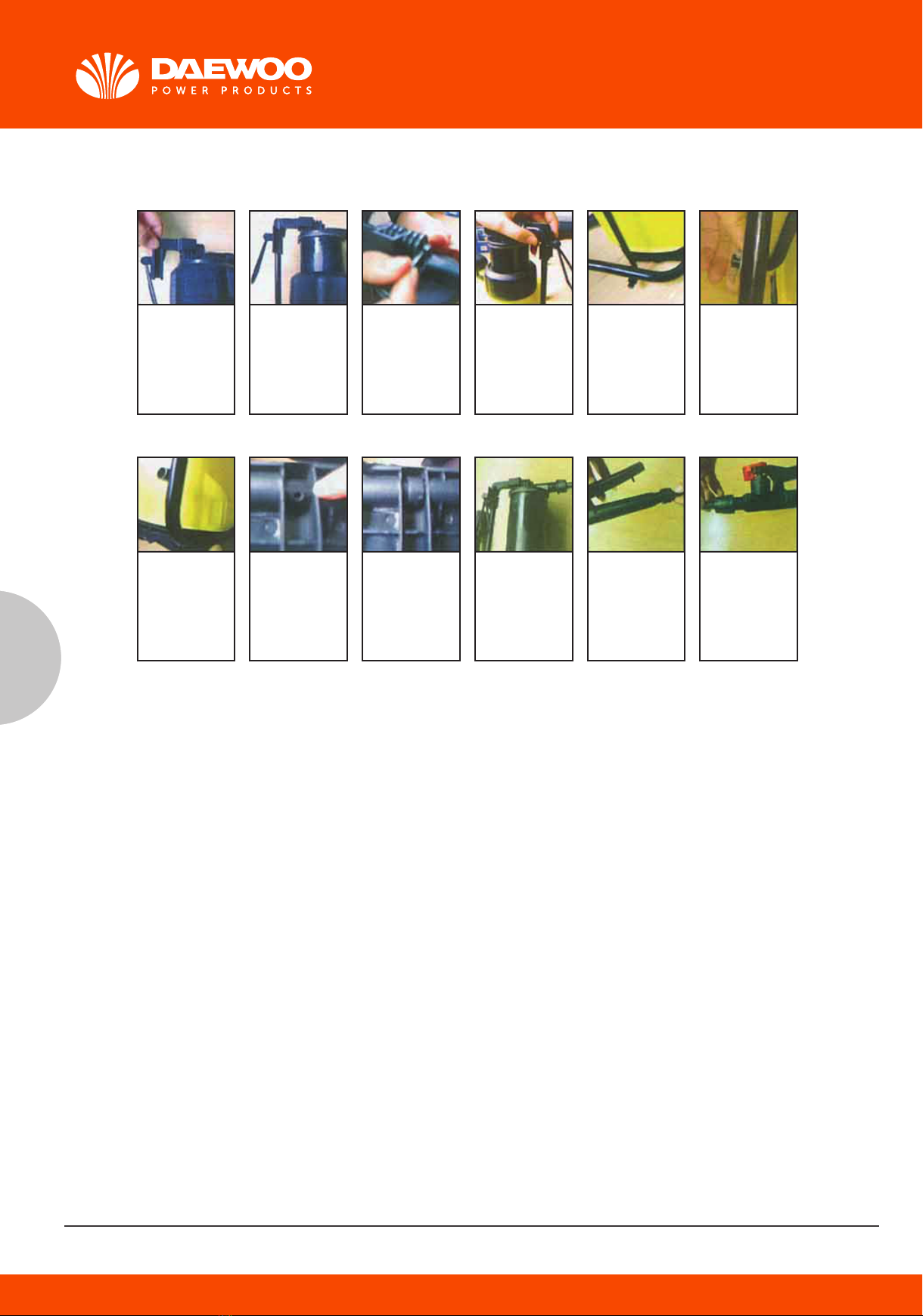
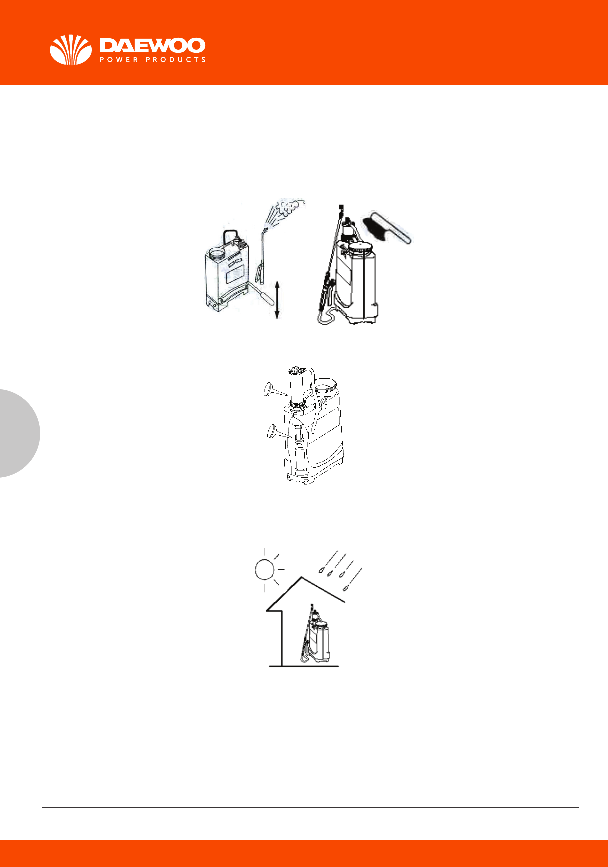
2. STRUCTURE, OPERATING PRINCIPLES AND FEATURES
STRUCTURE: This Sprayer consists of five units: a tank, a pump, a spraying unit (tube, switch, a
spray boom, and a spray head), a rock bar unit and a strap.
PRINCIPLES: The leather cup moves up/down in the pump cylinder due to the swinging of rock bar
unit to produce a pressure difference between the inside and outside of the pump which will drive
the valve sheet to open and close so as to pump the mixture into the chamber which will be sprayed
like fog through the spraying unit.
FEATURES
1. The tank is ergonomically designed to imitate the curve of human back to ensure
close contact with and comfortable carrying on the back. The built-in chamber offers compact and
leak-free structure.
2. Come with a piston pump to ensure simple, safe, leak-free and labour-saving operation.
3. It comes with a hold-and-release switchto allow flexible, leak-proof and sound operation, ideal for
both spot spraying and continual spraying.
4. A variety of nozzles are available depending on the practical demands to attain optimum spraying
result.
5. The whole unit is made of premium materials to ensure high resistance to acid, base and corro-
sion, in addition to proven air-tightness and durability.
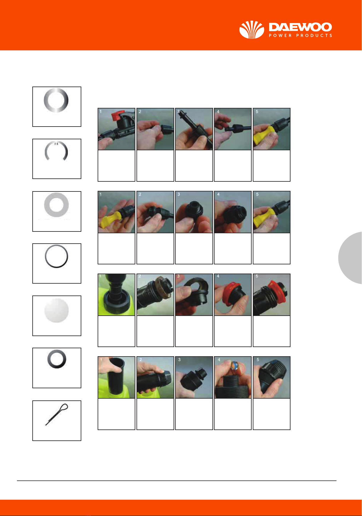
3. PART DESCRIPTIONS AND TECHNICAL SPECIFICATIONS
4. PRECAUTIONS
In addition to strict compliance with safety rules in the manual, you are required to :
1. Prohibit the use of special working fluid.
2. Follow the safety directions given by pesticide manufacturer in dealing with pesticides.
5. HAZARDS
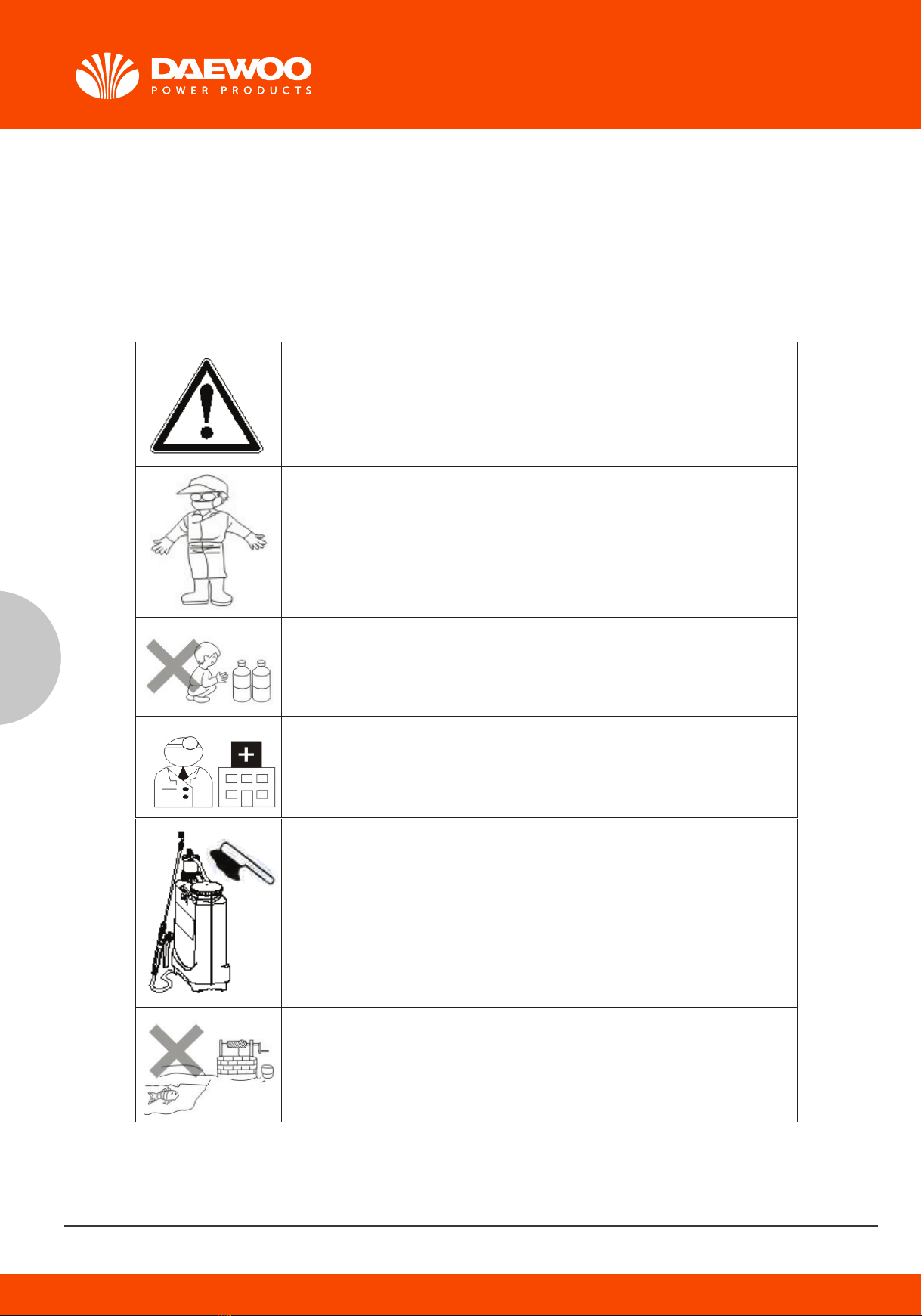
You are required to read this Manual and follow the instructions on opera-
tion and safety for purpose of proper operation.
The operator shall wear a mask, operation hat, protection clothes,
water-proof glove and rubber boot etc.
Storage and warehousing of pesticide. The pesticide shall be kept out of
the reach of children.
Disposal of pesticide shall follow the safety instructions furnished by its
producer.
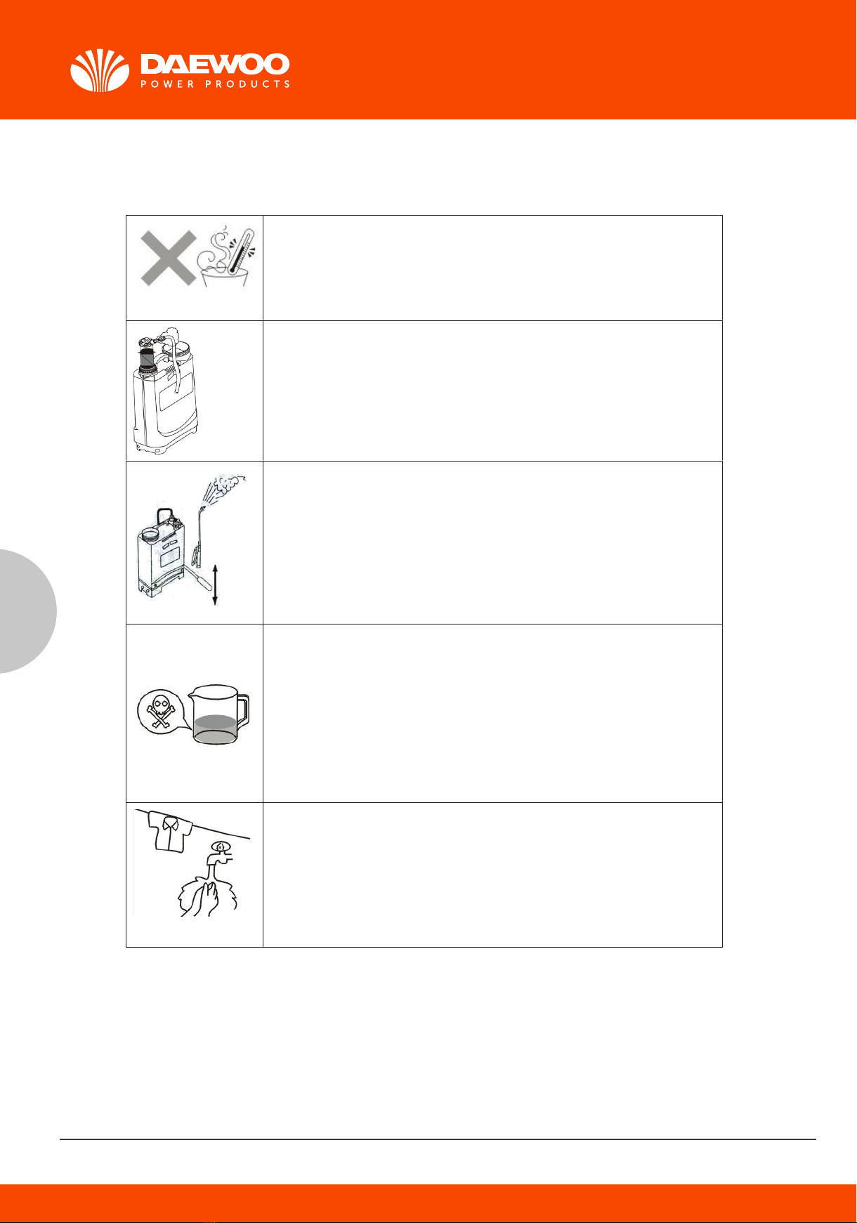
In case of inhaling: Immediately leave the poisonous place to a well-venti-
lated place to lie down for a rest. In case of intoxication via skin contact,
please rinse with water immediately.
In case of ingestion, induce vomiting with clean water or salt water and go
to hospital as soon as possible.
Upon finish of operation, the sprayer shall be cleaned to avoid possible
corrosion or blocking, while preventing the mixing of residues with chemi-
cal of next operation, which may compromise the spraying performance or
do harm to crops.
The residual chemical shall be kept in a container instead of being poured
into the field, ground and rivers. The empty bottles and bags shall either be
collected and sent to the manufacturer for proper disposal or buried in a
barren land with deep under-ground water level and small rainfall far from
living areas and water sources.