Daewoo DPX-32F1BMB User manual

Caution
: In this Manual, some parts can be changed for improving. their
performance without notice in the parts list. So, if you need the
latest parts information, please refer to PPL(Parts Price List)in
Service Information Center.
Service Manual
32" PLASMA PDP TV
CHASSIS :
Model :
S/M NO. : TSP901XEF1
SP-901X
DPX-32F1BMB


-3-
1. Safety Precautions
I. Parts with the exception of MODULE
(1) When moving or laying down a PDP Set, at least two people must work together.
Avoid any impact towards the PDP Set.
(2) Do not leave a broken PDP Set on for a long time. To prevent any further damages, after
checking the condition of the broken Set, make sure to turn the power(AC) off.
(3) When opening the BACK COVER, you must turn off power(AC) to prevent any electric
shock. When PDP is operating, high voltage and high current inside the Set can cause
electric shocks.
(4) When loosening screws, check the position and type of the screw.
Sort out the screws and store them separately for reassembling.
Because screws holding PCBs are working as electric circuit GROUNDING,
make sure to check if any screw is missing when assembling / reassembling.
Do not leave any screws inside the set.
(5) If you open the BACK COVER,
you will see a Panel Gas Exhaust Tube
(Picture. 1-1) inside the bracket.
If this part is damaged, the entire PDP
PANEL must be replaced. Therefore,
when working with the set, be careful not
to damage this part.
(6) A PDP Set contains different kinds of
connector cables.
When connecting or disconnecting cables,
check the direction and position of the cable
beforehand.
(7) Connect / disconnect the connectors slowly with care especially FFC(film) cables
and FPC cables.
Do not connect or disconnect connectors instantaneously with force, and handle them
carefully for reassembling.
(8) Connectors are designed so that if the number of pins or the direction does not match,
connectors will not fit.
When having problem in plugging the connectors, check their kind, position, and direction.
Picture.1-1 Panel Gas Exhaust Tube

-4-
2. Product Specification
2-1. Specification
ITEM SPECIFICATION REMARK
1. GENERAL.
1-1. MODL NO DPX-32F1BMB
1-2. CHASSIS NO SP-901X
1-3. SCREEN SIZE 32”(16:9)
1-4. COUNTRY Middle & South America
1-5. RESOLUTION 852(H) X 480(V)
1-6. REMOCON TYPE R-55F06
1-7. SAFETY STANDARD CB
1-8 .TUNING METHOD FS
1-9. MEMORY CHANNEL 181CH
2. MECHANICAL
2-1. APPEARANCE
1) WITHOUT STAND W x H x D = 825 x 561 x 87.8 mm
2) WITH STAND W x H x D = 825 x 603.2 x 233.6 mm
2-2. WEIGHT
1) WITHOUT STAND 18.5 Kg
2) WITH STAND 19.2 Kg
3. ELECTRICAL
3-1. VIDEO INPUT
COMPOSITE(NTSC, PAL, SECAM, PAL-M/N, NTSC4.43) 2 Ports &
S-VHS(50/60Hz Y/C) 2 Ports
3-2. DTV/DVD INPUT 1080i, 720P, 480P, 480i, 576P, 576i
(Y, Pb/Cb, Pr/Cr COMPONENT SIGNAL) 2 Ports
3-3. PC INPUT VGA ~ WXGA(Dot clock : 110MHz), 15 PIN D-SUB 1 Port
3-4. HDMI INPUT HDMI-H INPUT(HDMI Jack) 1 Port
3-5. TV INPUT
1) COLOR STANDARD NTSC-M, PAL M/N
2) ANTENNA IN ONE INPUT 75 Unbalanced (F-Type Standard)
3) RECEPTION CHANNEL VHF : Ch 02 ~ 13
UHF : Ch 14 ~ 69
CATV : Ch 1, 14 ~ 125
4) IF & SUBCARRIER PIF : 45.75MHz
SIF : 41.25MHz
3-6. SOUND INPUT VIDEO 2 Ports, DTV/DVD 2 Ports, PC/HDMI 1 Port
3-7. SPEAKER OUTPUT 10W(R) + 10W(L)
3-8. POWER REQUIREMENT AC 100V~240V, 50/60Hz

Product Specification
-5-
ITEM SPECIFICATION REMARK
3-9. POWER CONSUMPTION 200 W
3-10.Phone Jack(Upgrade) S/W Upgrade
3-11. AV OUTPUT CVBS, SOUND R/L 1 Port
3-12. FUNCTION
1) SCALING HDMI : Screen Mode(16:9, 4:3)
PC : Screen Mode(16:9, 4:3), H/V Position, Auto)
TV / AV : Screen Mode(16:9, 4:3, LB(16:9), LBS(16:9), 14:9,
LB(14:9), LBS(14:9)
COMPONENT : Screen Mode(16:9, 4:3)
2) OSD Language 4 Languages (English, Franch, Spanish, Portuguese)
3) PIP/POP TV, Video, S-Video / HDMI
4) OTHERS Still, Sleep Mode, Sound Mode, Timer, Screen Mode,
Closed Caption, MGDI, Picture Mode
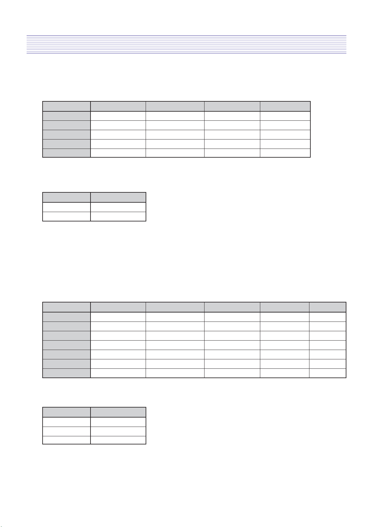
4. OPTICAL
4-1. SCREEN SIZE 32”(81 cm) DIAGONAL
4-2. ASPECT RATIO 16 : 9
4-3. NUMBER OF PIXELS 852(H) X 480(V)
4-4. DISPLAY COLOR 1,073,000,000 Colors (10 Bits for each RGB)
4-5. CELL PITCH 277um(H) X 830(V)um (1 Pixel = a Set of RGB Cells)
4-6. PEAK LUMINANCE Typical 550cd/m2 (25% White Window, 60Hz)
4-7. CONTRAST RATIO Average 60:1(In a bright room with 100Lux at center, 60Hz)
4-8. VIEWING ANGLE FREE
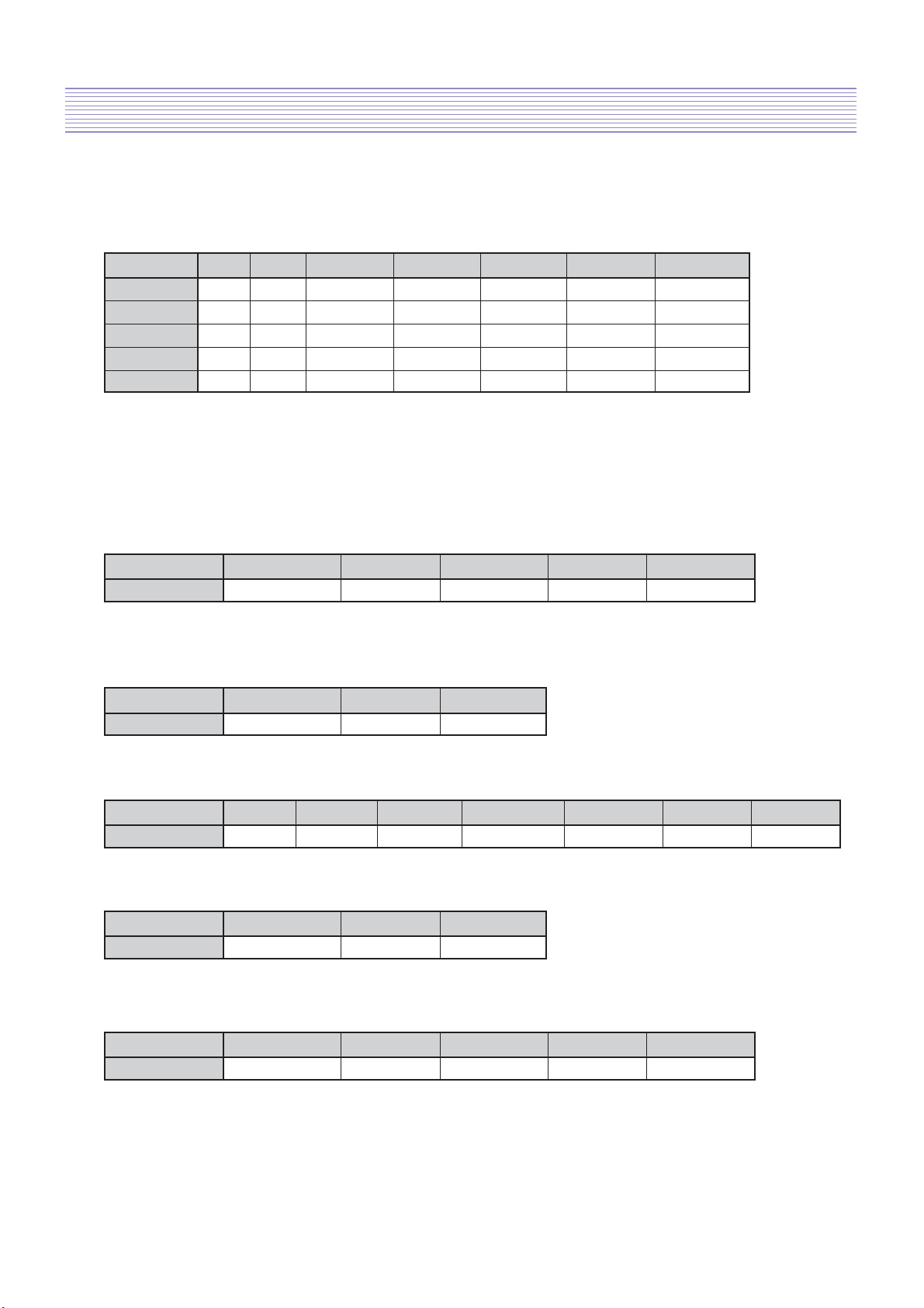
5.
USERCONTROL & ACCESSORIES
5-1 CONTROL BUTTON(SET)
SOFT S/W : MOVE/CH(UP, DOWN), VOLUME(LEFT, RIGHT),
MENU, INPUT SELECT, POWER
5-2. REMOTE CONTROL Power, Display, 10KEY(0~9), 100KEY, Still, Screen Size,
(R-55F06)
Menu, TV, AV, Multimedia, PREV CH, Mute, CH(UP/DOWN),
VOL(UP/DOWN), Caption, Picture Mode, Sound Mode, MTS,
Sound Effect, PIP, Ch Up(Sub), Sleep Timer, Add/Erase, Position,
5-3. ACCESSORIES
REMOTE CONTROL, INSTRUCTION MANUAL, POWER CORD
5-4. OPTIONAL PARTS STAND, WALL HANGER

Product Specification
-6-
2-2. Available Input Signal
1) PC&HDMI
2) Component
• 1080i - 50 / 60Hz
• 720p - 50 / 60Hz
• 480p/i - 50 / 60Hz
• 576p/i - 50 / 60Hz
3) Video
• PAL, PAL - M, PAL - N
• NTSC, NTSC 4.43
• SECAM
Resolution H.Freq.(kHz) V.Freq.(Hz) Remark HDMI PC
31.469 59.940 DOS O O
640 x 480 37.861 72.809 VESA O O
37.500 75.000 VESA O O
720 x 400 31.469 70.087 IBM O O
800 x 600 35.156 56.250 VESA O O
37.879 60.317 VESA O O
1024 x 768 48.363 60.004 VESA O O
1280 x1024 63.981 60.020 VESA O O

3. The Feature of Inside
-7-
Fig.2 Main PCBs Block Diagram
KEY
LED
PA101
P702
J151
J301
J855
PC851
IC101
PW338B
IC201
DDR SDRAM
IC202
DDR SDRAM
IC401
FLASH 16M
PCB MAIN
SP-901X
AV3
(Y/C, CVBS)
J853
J851
J802
J801
P801
J854
Upgrade
jack
PC
(D-SUB)
DVI & PC
Audio L/R
HDMI
SPDIF
_OUT
S-VIDEO1 MONITOR_OUT
VIDEO1
COMPONENT2
COMPONENT1
P701
TU901
TUNER PA103
IC751
MSP4650K
From PWR
From PWR
TO PDP MODULE
IC622
PIC16F690
IC701
STA515W
PC602
P109P108PC301 PC601
3-1. Main PCB’s Connection Diagram
Fig.3 Signal Block Diagram : DPX-
3-2. Block Diagram

-8-
The Feature of Inside
3-3. Power Specification

-9-
4. Default Setting in User Menu OSD
4-1. Picture
1) Mode
* HDMI & PC Input - Only brihgtness and contrast are available.
2) Default Value of Other Functions
* N.R. means the noise reduction
* HDMI & PC don't support N.R. functions
4-2. Sound
1) Mode
2) Default Value of Other Functions
Normal Dynamic Cinema User
Brightness 48 46 55 Undefined
Contrast 70 74 60 Undefined
Sharpness 7 8 6 Undefined
Colour 55 60 50 Undefined
Tint 50 50 50 Undefined
Function Default Value
Colour Temp Normal
N.R. On
Normal Movie Music News User
120 Hz 32 50 48 15 Undefined
200 Hz 32 50 48 15 Undefined
500 Hz 32 38 38 32 Undefined
1.2 kHz 32 28 15 50 Undefined
3 kHz 32 28 15 50 Undefined
7.5 kHz 32 40 42 32 Undefined
12 kHz 32 48 56 15 Undefined
Function Default Value
Balance 0
Effect Off
AVC Off

Default Settinf in User Menu OSD
-10-
* H. Position, V. Position, and Auto screen size is available in only PC mode.
4-3. Screen
1) Mode
4-4. Feature
1) Mode
4-5. Install
16 : 9 4 : 3 LB (16:9) LBS (16:9) 14 : 9 LB (14:9) LBS (14:9)
Component O O X X X X X
TV O O O O O O O
AV O O O O O O O
PC O O X X X X X
HDMI O O X X X X X
Function CH Mode Channel Memory Fine Tune Video
Default Value Cable 1 Erase 0 Auto
* HDMI & PC don’t support MGDI function.
2) Closed Caption
3) Time Setting
4) ISM
Function Background Language Child Lock MGDi plus Auto Power
Default Value 10 English Off On Off
Function Pixel Shift Low Bright Image Invert
Default Value Off On Off
Function Caption Mode Caption Box CC on Mute
Default Value Off Black Off
Function Clock Off Timer Off Time Wake Timer Wake Time Wake CH. Wake Vol.
Default Value Undefined Off PM 12:00 Off PM 12:00 1 20

5. Service Mode
-11-
To enter SERVICE MODE,
A. Press “VOL” -> “MUTE ” -> “RECALL” -> “MUTE” button of remote controller
(R-55F06)
or
B. Press “S9” button of SERVICE REMOTE CONTROLLER.
[Note] In the first line, there is the model name and the version of the upgraded program
on the PDP set.
5-1. Default Value of Pw338B_1 and Pw338B_2
O RGB offset values will be set by executing ‘RGB Auto Cal’ in service mode.
O YPbPr offset values will be set by executing ‘YPbPr Auto Cal’ in service mode.
1) Pw338B_1
O Sub Bias : For BRIGHTNESS adjustment (All inputs)
O Sub Gain : For CONTRAST adjustment (All inputs)
O Bias R : For R BRIGHTNESS adjustment (All inputs)
O Bias G : For G BRIGHTNESS adjustment (All inputs)
O Bias B : For B BRIGHTNESS adjustment (All inputs)
O Gain R : For R CONTRAST adjustment (All inputs)
O Gain G : For G CONTRAST adjustment (All inputs)
O Gain B : For B CONTRAST adjustment (All inputs)
2) Pw338B_2
O Sub Bias : For HDMI BRIGHTNESS adjustment
O Sub Gain : For HDMI CONTRAST adjustment
5-2. FrontEnd_1
Function R Offset G Offset B Offset R Gain G Gain B Gain
Default Value 512 512 512 512 512 512
Function Y Offset Pb Offset Pr Offset Y Gain Pb Gain Pr Gain
Default Value 512 512 512 512 512 512
Sub Bias Sub Gain Bias R Bias G Bias B Gain R Gain G Gain B
Pw338B_1 32 72 32 30 41 28 32 45
Pw338B_2 32 64

Service Mode
-12-
Function VEH 2D-Peaking BWE Enable BWE Gain BWE Mid gain
Default Value 1 0 0 4 2
Function BWE TCONST BWE BWCOFS HFILTER VFILTER
Default Value 5 16 6 6
O
The automatically set offset values may different from the default value depend on B/D.
However, the main B/D should be replaced or contact Kunpo R&D center in Korea if
the OFFSET values differ more than ±20 from default value.
5-3. FrontEnd_2
5-4. MGDI
5-5. Msp46X0
AV Brt AV Cont
FrontEnd_2 128 134
O In Msp46X0,
- Sc pScale : Prescale adjustment for external input (AV, Component, PC etc.)
- Fm pScale : FM/AM prescale adjustment
- BBE Level : BBE level control
- HDMI pScale: HDMI prescale adjustment
- Mvoice Level : Mvoice level control
- Audio Delay : Sound delay control
5-6. Misc
O Tst Ptrn AT shows five cycled patterns (white, black, red, green, blue) every 1 minute
automatically
O Tst Ptrn MA shows five cycled patterns manually by pressing volume up key.
Function Tst Ptrn AT Tst Ptrn MA TV Auto Off Search Mode
Default Value Undefined Undefined On 60Hz
Function Sc pScale Fm pScale HDMI pScale
Default Value 24 53 20
Function BBE pScale Mvoice Level Audio Delay
Default Value 30 12 40

Service Mode
-13-
5-7. Panel
Function Sync Mode Bright Mode Power Mode Gamma Mode Panel Temp
Default Value AUTO 100% 100% 2.2N **.*
O Panel Temp indicates the current temperature of the panel.
5-8. Reset
O Level 1 - Resets all data in E2PROM other than HDCP key, EDID, RGB offset
and YPbPr offset of FrontEnd_1.
O Level 2 - Resets all data in E2PROM other than the exception of Level 1 and
Pw338B_1.
O Factory - Resets the data of auto search, language setting, time setting, and the
user menu values that could be reset by ‘Initialize’ function in
Feature mode.

6. Adjusting method
-14-
6-1. MODULE POWER Adjustments and Test Point Locations
Video pattern condition : 100 IRE Full White Pattern
Adjust voltages (Vadd, Vsus) to the values that module maker labeled on the PDP panel.
If there are some problems in picture after adjusting, you should classify
that PDP module as a fault and contact to PDP module maker.
1) Vd (Vadd Voltage) : Data address voltage
- Measurement equipment : Digital Volt Meter (DC Volt mode)
- TP : P812 #3
- Adjusting Volume : VR901
- Adjusting Voltage : Voltage written in the Label, which is located in the upper
left side of PDP Module. (Typical Voltage : 60 ~ 65 V)
2) Vs (Vsus Voltage) : Sustain voltage
- Measurement equipment : Digital Volt Meter (DC Volt mode)
- TP : P812 #9
- Adjusting Volume : VR951
- Adjusting Voltage : Voltage written in Label, which is located in the upper left side
of PDP Module. (Typical Voltage : 180 ~ 188 V)
6-2. White Balance Adjustments
1) Apply 5 Step Gray Scale pattern to Video input terminal
2) Check initial data of User Menu [refer to 4-1. Picture (Normal)]
3) To enter Service mode, press button “VOL DOWN -> MUTE -> DISPLAY -> MUTE”
on the remote control and select PW338_1, then check initial data of Service mode
[refer to 5. Service Mode].
100% 80% 60% 40% 20% 0%
High Level Reference Low Level Reference

Adjusting method
-15-
4) Attach a sensor of White Balance Meter (CA-100) to 80% of white level on the screen.
5) Adjust White Balance by varying Gain of R, G, B
•
Gain of R, G, B should be adjusted to DP ±10, if out of these range then classify as a fault.
• Set Color Coordinate to x=0.275 ±0.005, y=0.285 ±0.005 (Low : 0.295) and the Color
Temperature should be over 10,000-degree K (standard R&D center equipment).
6) Attach a sensor of White Balance Meter to 40% of white level on the screen.
7) Adjust White Balance by varying the BIAS values of R, G, B
• BIAS Values of R,G,B should be adjusted to DP ±10 ,if out of these range then classify
as a fault.
• Set the Color Coordinate to x=0.275 ±0.003, y=0.295 ±0.003
(standard R&D center equipment).
• Does not need to adjust if the deviation of color coordinate is within ±0.003.
8) Repeat No 4) to No 7) until getting the Color Coordinate is x=0.275 ±0.003,
y=0.295 ±0.003 at 40% and x=0.275 ±0.005, y=0.285 ±0.005 at 80% white level.
Then adjust Sub Contrast to over 140 Cd/m2after attaching a sensor of White Balance
Meter to 100% of white level on the screen.
9) To exit from Service mode, press Menu button on the remote control.

7. Noticeable Points While Assembling
-16-

Noticeable Points While Assembling
-17-

8. Software Upgrade Methord
-18-
PICkit 2 Micro Controller Programmer
PICkit 2 Connector Pinout
8-1. Pic upgrade

Software Upgrade Methord
-19-
1) Main pcb Power off
2) Connecting the Pic upgrade board to Main pcb as shown below

Software Upgrade Methord
-20-
3) Run PICkit 2 Microcontroller Programmer
4) Please confirm if pickit 2 microcontroller programmer deteced device(PIC16F690)
appropriately or not
Table of contents
Other Daewoo Plasma TV manuals

Daewoo
Daewoo DPA-5034LDS User manual

Daewoo
Daewoo DLP-17D3 User manual

Daewoo
Daewoo DPP-42A1GCSB User manual

Daewoo
Daewoo DTS-42HDT User manual

Daewoo
Daewoo DPN-4274NHS User manual

Daewoo
Daewoo PXT-42BSTD User manual

Daewoo
Daewoo DPP-42A1LASB User manual

Daewoo
Daewoo DSP-4210GM User manual

Daewoo
Daewoo DPP-32F1BMB User manual

Daewoo
Daewoo DPP-42A1LCSB User manual