Daewoo Novus M2SEF User manual

FOREWORD
WewouldliketotakethisopportunitytothankyouforchoosingaTATA
DAEWOOproductandassureyouforourcontinuinginterestinyour
motoringpleasureandsatisfaction.
Thismanualhasbeenpreparedtoacquaintyouwiththeoperationand
maintenanceofyournewTATADAEWOOTRUCKandtoprovide
importantsafetyinformation.Weurgeyoutoreaditcarefullyandfollow
therecommendationtohelpassurethemostenjoyable,safeand
trouble‐freeoperationofyourvehicle.
Whenitcomestoservice,rememberthatyourTATADAEWOOdealer
knowsyourvehiclebestandisinterestedinyourfullsatisfaction.
Thismanualshouldbeconsideredasapermanentpartofyourvehicle,
andmustremainwiththevehicleatthetimeofresale.
Allinformation,illustrationsandspecificationscontainedinthismanual
arebasedonthelatestproductinformationavailableatthetimeof
publication.
Therightisreservedtomakechangesatanytimewithoutnotice.
TATADAEWOOCOMMERCIALVEHICLE
FOREWORD
https://www.truck-manuals.net/

TABLE OF
CONTENTS
1. HOW TO HANDLE THE VEHICLE
2. DRIVING
3. INSPECTION AND
MAINTENANCE
4. TROUBLE SHOOTING AND
CORRECTIONS
5. MISCELLANEOUS CONTROLS
AND OPTIONS
6. SPECIFICATIONS AND SERVICE
https://www.truck-manuals.net/

HOWTO HANDLETHEVEHICLE
1. OPERATION OF NEW VEHICLE
2. OPERATION OF CAB TILT
3. OPENING OR CLOSING OF FRONT LID
4. INSTRUMENTS AND CONTROLS
1) Attachments of steering column
2) Peripheral devices of steering column
3) Instruments and indicator lamps
4) Controls of center console
5) Miscellaneous controls
https://www.truck-manuals.net/

1. OPERATION OF NEW VEHICLE
1-1 HOW TO HANDLE THE VEHICLE
It is important to follow the instructions as outlined here,
because careful breaking-in of your vehicle will greatly
increase its life and performance.
Engine type
MTA0011
Service intervals for changing
engine oil and filter
1) Follow oil change interval.
For further information, refer to "Recommended
DE
DV
DDC
At end of first 1,000km
Short distance travel(in city):
every 10,000km
Long distance travel(at high
speed): every 15,000km
Every 15,000km
* Lubricants".
When this vehicle was released, engine oil
added with abrasive material was used for its
diesel engine(DE/DV). So, make sure to change
the engine oil after the first 1,000 km.
*
Oil must be replaced at least every 6 months.
MTA0020
2) Follow the instructions on how to operate
the new vehicle.
It is necessary to allow the moving parts of the
new vehicle to break in for the first 4,000 km.
(1) Warm up the engine after starting it. In cold
weather, especially, warm up the engine suffi-
ciently before starting off.
(2) Do not abruptly increase rev during idling.
(3) Avoid jack-rabbit starts, abrupt acceleration, or
sudden stops.
MTA0031
https://www.truck-manuals.net/

1-2HOWTOHANDLETHEVEHICLE
DDC (4) During the first 4,000 km, limit engine speed to
70 percent of the maximum allowance, and
frequently watch tachometer to prevent engine
over-running while driving your vehicle.
Maximum allowable engine speed (rpm)
Engine First 4,000 km After 4,000 km
DE12TI 1,470 2,100
DE12TIS 1,470 2,100
DV15T 1,600 2,300
MTA0090 MTA0091 DV15TI 1,470 2,100
DV15TIS 1,470 2,100
DDC 1,260 1,800
3) Through check should be performed ac-
cording to "CONTROLS AND INSTRU-
MENTS" and "BEFORE DRIVING OFF".
MTA0050
4) In order to operate your vehicle safely and
dependably, it is imperative to perform ne-
cessary inspection and adjustment as out-
lined in "INSPECTION AND MAINTE-
NANCE".
MEA0021
MTA0071
5) Overloading may not only shorten the ser-
vice life of your vehicle but also cause seri-
ous problems against your safety. The weight
of the payload must be within the GVW rat-
ing and distributed over the front and rear
axles so as not to exceed their axle capaci-
ties. Refer to "SPECIFICATIONS AND SER-
VICE DATA" for GVW and Axle capacity.
https://www.truck-manuals.net/

1-3 HOW TO HANDLE THE VEHICLE
6) How to Handle the vehicle(for DDC engine)
(1) IDLE SHUT DOWN function
1) Engine automatically stops after 5 minutes
passed when engine is idling for reducing
fuel consumption and air pollution
2) Restart engine for driving after engine has
stopped automatically
Caution
MTA0041
MTA0042
1. Limit idling time within 10% (1 hour approximately)
of during initial driving of 15 hours.
2. Unnecessary idling during initial operation could
damage electrical fuel injection system(ECU)
•3 minutes of engine warming-up is enough in
winter time.
(2) Cautions for engine abnormalities during driv-
ing
1) Check Engine indicator : indicates engine's
malfunction, power is limited to 70% of total
level automatically.
2) Stop Engine indicator : indicates serious prob-
lems on engine, power is limited to 40% of
total level, Move the truck to safe place within
the time before engine automatically stops
after 30 seconds of indication. Press the
switch within 25 seconds after indicator came
up for extending operation time as much as
30 seconds. (refer to page 45, "Engine di-
agnosis switch")
https://www.truck-manuals.net/

1-4 HOW TO HANDLE THE VEHICLE
6) Seat belts
Always fasten your seat belts when driving over long
distance or in downtown. Passengers not wearing
their seat belts may endanger your safe driving.
MTA1120
*
The seat belt warning lamp comes on when the
ignition switch is placed in the "ON" position
unless the driver's seat belts are securely
fastened.
MTA0561
WARNING CARE OF BELTS
1. Never use a belt for more than one person
at a time.
2. Never wear the belts twisted.
3. Make sure seat belts or their attachments not
to be thrusted in metal parts of the seat or
the door.
4. Seat belts should be adjusted as firmly as
possible.
5. Do not wear seat belts low under your shoul-
der.
6. If you replace your seat belts incorrectly, you
may be injured by hardwares of the belts at
sudden stops.
7. Do not wear your seat belts with hard or
breakable objects such as glasses, pens,
etc. put into the pocket of your upper
garment.
1. Periodically inspect all parts of the belts and
replace any damaged parts.
2. Make sure that the belts are not to be
damaged by sharp edged objects.
3. The belts should be changed if webbing has
become frayed or damaged.
4. Check if fixing bolts have been firmly
installed to the floor.
5. Always keep the seat belts clean and dry.
6. Clean only with tepid soapy water. 7. Do
not bleach or dye seat belts.
https://www.truck-manuals.net/

2. OPERATION OF CAB TILT
MTA1181
1-5 HOW TO HANDLE THE VEHICLE
1) Preparation for cab tilting
(1) Place the vehicle on level ground and ensure
that there is a sufficient space in front of and
above the cab. And then, position starter switch
"ON".
(2) Set the parking brake firmly.
(3) Set the gearshift lever to neutral position.
(4) Keep interior of the cab free from fragile articles.
Close the doors securely.
(5) All the wheels should be choked.
(6) Re-check if there is any person in the cab.
(7) Open the cab according to the following instruc-
tions.
Note
Read thoroughly "CAB TILT OPERATING INS-
TRUCTIONS" affixed at the rear right-hand side of
the cab before manipulating it.
•Recommended cab tilt oil
Specifications : EQUIVIS ZS15(manufactured
by ISU)
MTA1191 Caution
Be sure to use recommended cab tilt oil replenish-
ment.
2) How to lift the cab
(1) Pull forward lock lever located at the lower right-
hand side of the rear of the cab while lifting the
hook
lock lever
MTA1260
hook to release lock.(Except for the vehicle that
the hydraulic cab lock option system is applied)
(2) Turn the direction change lever installed onto
the pump located at the rear lower right-hand
side of the cab to set it to "U" position.
(3) If you insert cab tilt lever into pump socket and
move it up and down, the cab will ascend.
Note
Although hydraulic pump does not work at the first
time, continue the manifulation as above, then the
cap will be tilted.
MTA1250
https://www.truck-manuals.net/

1-6 HOW TO HANDLE THE VEHICLE
3) How to lower the cab
(1) Position the direction change lever in "D" posi-
descending tion.
position
MTA1231
(2) If you insert cap tilt lever into pump socket and
move it up and down, cab will descend.
(3) Make sure that lock lever is locked into hook.
(Except for the vehicle that the hydraulic cab
lock option system is applied)
MTA1250
Inside the cab
4) How to lift the cab (Hydraulic cab latch :
option)
(1) Pull forward lock lever located at the lower right-
hand side of the rear of the cab while lifting the
hook, and then the lock will be released.
Hook
Lock
lever
MTA1240
tilting
position
MTS0190
MTA1210
Push cab tilt enable switch to "ON" position lo-
cated in instrument panel inside the cab in case
of the hydraulic cab lock option system is ap-
plied in the vehicle.
(2) Turn the direction change lever installed onto
the pump located at the rear lower right-hand
side of the cab to set it to "U" position.
(3) Press the switch as shown, and then the pump
works and the cab starts to ascend.
https://www.truck-manuals.net/

1-7 HOW TO HANDLE THE VEHICLE
(4) Cab is ascending while pushing the cab-tilt
switch. You can manipulate the switch to adjust
open angle of the cab as desired. Stop pushing
the switch when the cab is tilted over than the
cab weight center, if you keep pushing the
switch on the noise will be increased.
Caution
1. If you want to stop ascending the cab, you
should position the direction change lever in "D"
position.
MTA1220 2. Do not work without tilting the cab completly.
3. Do not start engine when the cab does not tilted
completly or while descending.
4. Never tilt the cab at a sloped hill.
descending
position
MTA1230
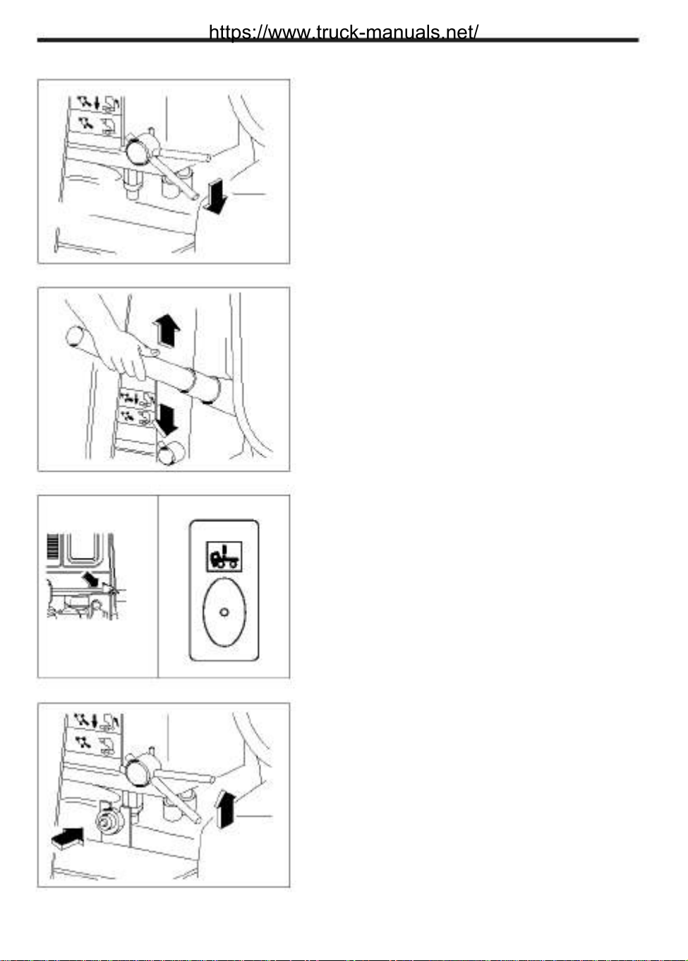
5) How to lower the cab (Hydraulic cab latch :
option)
(1) Position the direction change lever in "D" posi-
tion.
(2) Press the switch as shown, and then the pump
works and the cab starts to descend.
(3) Once the cab descended completly, stop push-
ing the switch.
Inside the cab
(4) Once the cab descends completely, check that
the lever located at the rear lower right hand
side of the cab is locked into hook.
For hydraulic cabin latch type vehicle, Make
sure that release cab tilt switch to "OFF" and
Hook warning lamp is off before driving.
Lock
lever
MTA1240
MTS0190
Caution
1. While driving you should set the direction change
lever in "D" position.
2. Be sure to check that the lock lever is locked in
hook. In the event of troubles with cab tilting sys-
tem, call for check and necessary services of your
nearest Daewoo dealer.
https://www.truck-manuals.net/

1-8 HOW TO HANDLE THE VEHICLE
3. OPENING OR CLOSING OF FRONT LID
1) Opening procedure
(1) Pull forward the front lid lever located at lower
left-hand side of the instrument panel.
hook
MTA1150
(2) Put your hand between the front lid and radia-
tor grille to pull forward the hook located in the
middle of the front part, and then the front lid
becomes unlocked.
(3) Pull the front lid to open.
5
3
4
2
1
MTA1160
MTA1140
MTA1171
(4) Opening the front lid enables you to easily
check, top-up, or clean the following parts.
1. Clutch fluid reservoir
2. Washer fluid tank
3. Engine oil level gauge
4. Engine oil filler
5. Air filter
2) Closing procedure
(1) Push the front lid slowly to close. Keep pushing
it until a "click" is heard from its lower part.
(2) Make sure that it is locked securely.
https://www.truck-manuals.net/

4. INSTRUMENTS AND CONTROLS
3
4
5
1-9HOW TO HANDLE THEVEHICLE
9
8
9
1
9
2
12
6
9
13
7
14 15
9
6
2
1
9
9
8
9
11
16 10 18 19
21
23
25
24
2 10 11
17 20 27 28 29 2630 31 3233 MTS0121
22
1. Speaker 15. Cigarette lighter 26. Trailer hand brake
2. Overhead stowage
3. Digital clock
4. Fluorescent room lamp
5. Spot lamp
6. Sunvisor
7. Inside rearview mirror
8. Side mirror
9. Ventilation vents
10. Door inside knob
11. Power window switch
12. Instrument panel
13. Controls of center console
14. Radio and cassette tape
holder
16. Side mirror adjusting switch
(option)
17. Front lid opening lever
18. Combination switch
19. Wiper and exhaust brake switch
20. Steering wheel adjusting lever
21. Starter switch
22. Dump control lever
23. Air parking brake valve
24. Idle control knob(DE/DV Engine)
25. Transmission gearshift lever
(tractor, pull cargo)
27. Clutch pedal
28. Brake pedal
29. Accelerator pedal
30. Ash tray
31. Consent
(12V : option)
32. Fuse and relay box
33. Cup holder
https://www.truck-manuals.net/

1-10 HOW TO HANDLE THE VEHICLE
1) Attachments of steering column
•Steering wheel and horn button
The steering wheel should not be turned while
the vehicle is stationary as it adversely affects
the tires and steering system.
Horn button is equipped on the middle of
steering wheel.
60mm
lock
unlock
MTA0130
10
MTA0140
MTA0220
•
•
Steering wheel adjustment
Adjust the steering wheel to the desired position
after pulling lock lever.
Adjusting angle: 10
Travel: 60mm
Starter switch
Starter switch operates in the 4 stages as fol-
lows:
(1) LOCK: The key can be inserted or removed
only when the switch is in this position.
(2) ACC : This position turns on the radio, digi-
tal clock, cigarette lighter and consent.
(3) ON : This position turns on the electrical
equipment. During the vehicle operation,
hold the key in this position.
(4) START : Once the engine is started, it is
preheated automatically according to out-
door temperature(DE: for 20 sec., DV: for 6
ON min, or until coolant temp, rises to 25C).
ACC START This improves the engine condition.
LOCK Caution
•Once the engine is started, release the key im-
mediately.
•Do not exceed 10 seconds for the operation of
starter.
•Gearshift lever should be in neutral position
when attempting to start the engine.
MTA0230
https://www.truck-manuals.net/

1-11 HOW TO HANDLE THE VEHICLE
MTA0621
MTA0150
•
Caution
1. Daewoo heavy trucks are equipped with the preheat-
ing and postheating systems designed to improve
engine starting and to reduce the generation of white
smoke.
2. With the starting key positioned "On", it is automati-
cally preheated according to the temperature of cool-
ant. In 0.3 second(in hot season) or 18 seconds(in cold
season), the preheating indicator lamp goes out, indi-
cating that preheating is complete.
•hot season: above 10Cof coolanttem-perature(DE
engine), or above 25C(DV engine)
•coldseason: below10Cof coolanttem-perature(DE
engine), or below 25C(DV engine)
3. If you start the engine before the preheater warning
lampgoes out,the postheatingsystemwouldnotwork,
resulting in increase in white smoke.
4. For 24ton dump truck, the engine is preheated by
Electronic Control Module (ECM)
Turn signal switch
Move this combination switch lever in the
desired direction so that the corresponding turn
signal lamp operates and causes the turn signal
indicator lamp on the instrument panel to flash.
The switch lever returns automatically to the
neutral position when the steering wheel is
returned to the reverse direction. When head
lamp switch is in 2nd stage simultaneously with
turn signal lamp "ON", cornering lamp also
comes on.
high beam
(passing)
low beam
high beam
1st
stage
OFF
2nd stage
MTA0160
MTA0170
•
•
•
High beam switch
When the head lamps are on, pulling the lever
down lights up not only the head lamps with high
beam but also the high beam indicator lamp.
When pulling it up, head lamps with low beam
are on.
Passing lamp switch
To light up passing lamps at any time, pull up
the lever towards the steering wheel. The lever
will return to the OFF position when released.
Lamp switch(turn type)
Lamp switch operates in two stages as follows:
1st stage: tail lamp, license plate lamp, ins-
trument panel lamp, clearance lamp
2nd stage: tail lamp, license plate lamp,
instrument panel lamp, clearance
lamp, head lamp, cornering lamp
(simulaneously with turn signal
lamp "ON")
https://www.truck-manuals.net/

1-12 HOW TO HANDLE THE VEHICLE
4
3
2
1
•
Windshield wiper switch
The windshield wiper switch has 3 positions to
control the windshield wiper.
1. OFF = Off
2. INT = Intermittent wipe
3. LO = Continuous wipe, slow speed
4. HI = Continuous wipe, fast speed
MTA0180
MTA0190
•
•
•
Caution
Do not operate the wipers when the windshield
remains dry. They may scratch the windshield glass.
Do not operate the wipers if they are covered with
snow or ice as this may damage the wiper system.
Wiper speed control switch
The desired intermittent operation time can be
controlled by turning the knob when the wiper
switch is in "INT" position.
Windshield washer switch
To let washer fluid spray on the windshield,
press and hold the center button of switch. And
the windshield wipers are simultaneously
operated for 2-3 cycles.
Exhaust brake switch
The exhaust brake system is designed to shut
off exhaust pipe when the engine brake is ap-
plied, resulting in assisting brake action. When
the switch lever is pushed downward, and clutch
and accelerator pedals are released, the indi-
cator lamp comes on showing that the ex-haust
brake is in operation. When the clutch and ac-
celerator pedals are depressed, the exhaust
brake stops working.
MTA0200 * In the case of 24ton dump truck, this opera-
tion is done by using the Jake Brake switch.
For detail, refer to "Jake brake switch" .
•Hazard warning flasher switch
When the right-hand lever is pushed upward,
all the turn signal lamps are made to flash
regardless of the turn signal switch position.
The hazard warning flasher switch is to be used
when your vehicle gets in a traffic hazard or is
parked in the darkness.
MTA0210
https://www.truck-manuals.net/

1-13 HOW TO HANDLE THE VEHICLE
2) Peripheral devices of steering column
8
1
2
34
5
6
(1) Differential lock switch(FRT/RR)
(2) Differential lock switch(L/R)
(3) Air conditioning switch
(4) Fog lamp switch
(5) Air parking brake valve
(6) Idle control Knob(for DE/DV Engine)
(7) Front lid opening lever
(8) Side mirror adjusting switch(option)
7
MTS0253
(1) Differential lock switch(FRT/RR)
In the case of two rear axle drive type vehicle, if
either rear axle falls in the mire to cause slip-
page, you must first stop your vehicle and then
place differential lock switch to "ON" position in
order to easily get out of the mire. The warning
buzzer keeps sounding all the while differential
lock is in operation.
MTS0733
(2) Differential lock switch(L/R)
If it is difficult to get your vehicle out of the mire
even by using the differential lock switch which
distributes power to both front and rear axles,
operate the differential lock switch(left/right). If
all the differential lock switches are energized
simultaneously, your vehicle will show a ten-
dency to travel straight. Be careful of this.
MTA0732
Tips for using differential lock system
* This system cannot be used if the wheels in
connection with the two rear axles are idled
simultaneously.
Caution
Do not exceed 30 seconds for one time use of this
system. If it is not possible to get out of the mire even by
using this system once or twice, do not use it any more.
Your vehicle requires towing. Continuous use of
differential lock system may cause defects to ring
MTA0741 gear set of rear axles and other drive systems.
https://www.truck-manuals.net/

1-14 HOW TO HANDLE THE VEHICLE
(3) Air donditioning switch
Pressing this switch turns on the air conditioer
and indicator lamp simultaneously.
MTA0681
(4) Fog lamp switch
Fog lamps provide auxiliary illumination and
improve your vision in fog or snow.
MTA0691
(5) Air parking brake valve
When the valve knob is pulled, the parking brake
is actuated to cause the indicator lamp to come
on. Pushing in the valve knob releases the
brake. Make sure that the indicator lamp is off
KPAR before driving off.
KERAGB
RKIN
PA BW
HPUS
MTA0290
ascending
position
MTA0300
(6) Idle control knob(For DE/DV engine)
Turning the knob clockwise after cold starting
of the engine will increase idling speed and thus
facilitate quick normalization of the engine cool-
ant temperature.
Always drive with the knob turned back home.
Caution
1. Do not use this knob to stop the engine.
2. For DDC engine, as idle speed is controlled auto-
matically, you need no special operation.
T
L
SE
FU
L
RELE
A
T
O
https://www.truck-manuals.net/

1-15 HOW TO HANDLE THE VEHICLE
(7) Front lid opening lever
When this lever is pulled up, front lid is re-
leased from locking to be ready to open. The
levels of engine oil, clutch fluid, and washer
fluid can be checked from inside the front lid.
Side mirror
adjusting switch
MTA0320
(8)
Side mirror adjusting switch(option)
Side mirrors can be adjusted by using this
switch from inside your vehicle.
Press the angle adjust button with arrow
marks to adjust the mirror angles.
Caution
Adjust mirror angles before driving.
1. Side mirror selection switch
MTS0260 : left : right
2. Side mirror four way control switch. To
adjust the outside mirrors turn the ignition
"ON"
https://www.truck-manuals.net/

1-16 HOW TO HANDLE THE VEHICLE
3) Instruments and indicator lamps
11
10
10
7
1
2
3
4
BULB
CHECK
5811 96
MTD0590
1. Blank 5. Air pressure gauge 9. Illumination control switch
2. Temperature gauge 6. Engine tachometer 10. Turn signal/hazard warning indicator
3. Fuel gauge 7. Tachograph 11. Miscellaneous indicator lamps and
4. Engine oil pressure gauge 8. Bulb check switch warning lamps
(1) Temperature gauge
The gauge indicates the engine coolant
temperature. If the gauge needle stands below
the red colored zone, it means that engine
coolant temperature is normal.
If the needle stands in "H"(overheating), stop
the vehicle and run the engine at a moderately
fast idle speed or put the gear in lower position
to reduce engine load. If the vehicle is operated
in abnormal condition, engine performance will
be reduced and fuel consumption will be
MTA0350 increased.
https://www.truck-manuals.net/

1-17 HOW TO HANDLE THE VEHICLE
(2) Fuel gauge
This gauge indicates fuel level of the fuel tank
all the time regardless of the starter switch po-
sition.
MTA0360
(3) Oil pressure gauge
This gauge indicates oil pressure in the engine
lubricating system. The indication of the gauge
should be 1-3kg/cm2when the engine is at idle; it
should be 3-6.5kg/cm2when the engine is
running at medium speed.
MTA0370
MTS0380
(4) Air pressure gauge
Air pressure gauge indicates air pressure in the
air tanks. While driving, the gauge needle must
be within the range of 5.3-8.2kg/cm2.
Be habitual of watching the gauge, while driv-
ing, to make sure the gauge needle indicates
the normal condition.
Caution
If the gauge needle stands in the red zone, warn-
ing lamp comes on and alarm buzzer sounds. Im-
mediately stop the vehicle, check for unusual con-
ditions, run the engine at a moderately fast idle
speed to increase air pressure, then drive off.
DDC Engine (5) Engine tachometer
The tachometer indicates the engine speed in revo-
lutions per minute(rpm) and red colored zone repre-
sents critical engine speed.
Excessively high engine rpm(red colored zone) may
cause damage to the engine. To drive economically,
keep the engine within 1,000-2,000(1,000-1,700:for
DDC engine) rpm.
Maximum allowable engine speed:
DE12TI Engine : 2,100 rpm
DE12TIS Engine : 2,100 rpm
DV15T Engine : 2,300 rpm
MTA0090 MTA0091 DV15TI Engine : 2,100 rpm
DV15TIS Engine : 2,100 rpm
DDC Engine : 1,800 rpm
https://www.truck-manuals.net/
This manual suits for next models
17
Table of contents
Other Daewoo Truck manuals