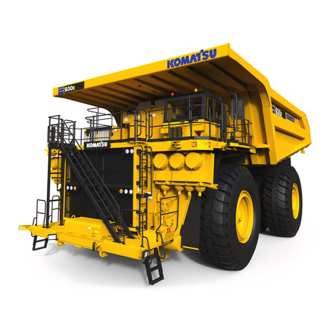
Komatsu 530M Manual


This material is proprietary to Komatsu Mining Systems, Inc. and is not
to be reproduced, used, or disclosed except in accordance with written
authorization from Komatsu Mining Systems, Inc.
ItisthepolicyoftheCompanytoimproveproductswheneveritispossible
andpracticaltodoso.TheCompanyreservestherighttomakechanges
oraddimprovementsatanytimewithoutincurringanyobligationtoinstall
such changes on products sold previously.
Because of continuous research and development, periodic revisions
may be made to this publication. Customers should contact their local
distributor for information on the latest revision.
CALIFORNIA
Proposition 65 Warning
Diesel engine exhaust and some of its constituents are known to
the State of California to cause cancer, birth defects and other
reproductive harm.
Unsafe use of this machine may cause serious injury or death.
Operators and maintenance personnel must read and understand
this manual before operating or maintaining this machine.
This manual should be kept in or near the machine for reference,
and periodically reviewed by all personnel who will come into
contact with it.


FOREWORD
This Manual is written for use by the operator and/or the service technician and is designed to help these persons to
become fully knowledgeable of the truck and all its systems in order to keep it operating safely and efficiently.
All operators and maintenance personnel should read and understand the materials in this manual before operating
thetruckorperforming maintenance and/oroperationalchecksonthe truck.Allsafetynotices,warningsand cautions
should be understood and followed when operating or accomplishing repairs on the truck.
The first section is an Introduction to the manual and contains a Table of Contents to locate specific areas of interest.
Other sections include Safety, Operation, Maintenance, Specifications, and Optional Equipment.
The illustrations used in this manual are TYPICAL of the component shown and may not be an exact reproduction of
what is found on the truck.
This manual shows dimensioning of metric and (U.S. standard) units throughout. All references to ‘‘Right’’, ‘‘Left’’,
‘‘Front’’,or‘‘Rear’’ aremadewithrespect totheoperator’snormalseatedposition,unless specificallystatedotherwise.
Standard torque requirements are shown in torque charts in the Introduction section and individual torques are
provided in the text in bold face type, such as 723 kg.m (100 ft.lbs.) torque. All torque specifications have ±10%
tolerance unless otherwise specified.
A Product Identification plate is normally located on the truck frame upright in front of the left side front wheel and
designates the Truck Model Number, Product Identification Number (vehicle serial number), and Maximum G.V.W.
(Gross Vehicle Weight) rating.
The Haulpak Model designation consists of three numbers and one letter (i.e. 530M). The three numbers represent
thebasic truck model. The letter ‘‘M’’ designatesaMechanicaldrivesystem,andtheletter‘‘E’’ designates an Electrical
wheelmotor drive system.
The Product Identification Number (vehicle serial number) contains information which will identify the original
manufacturingbillofmaterial forthisunit.Thiscompletenumber willbenecessaryforproper ordering of manyservice
parts and/or warranty consideration.
The Gross Vehicle Weight (GVW) is what determines the load on the drive train, frame, tires, and other components.
The vehicle design and application guidelines are sensitive to the total maximum Gross Vehicle Weight (GVW) and
this means the TOTAL WEIGHT: the Empty Vehicle Weight + the fuel & lubricants + the payload.
To determine allowable payload:
Service all lubricants for proper level and fill fuel tank of empty truck (which includes all accessories, body liners,
tailgates, etc.) and then weigh truck.
Record this value and subtract from the GVW rating. The result is the allowable payload.
NOTE: Accumulations of mud, frozen material, etc. become a part of the GVW and reduces allowable payload. To
maximize payload and to keep from exceeding the GVW rating, these accumulations should be removed as often as
practical.
Exceeding the allowable payload will reduce expected life of truck components.
OM1006.1 10/98 Introduction - Section 1
Page 1-1

‘‘DANGER’’ identifies a specific potential hazard
WHICH WILL RESULT
in either INJURY OR DEATH
if proper precautions are not taken.
‘‘WARNING’’ identifies a specific potential hazard
WHICH MAYRESULT
in either INJURY OR DEATH
if proper precautions are not taken.
‘‘CAUTION’’ is used for general reminders
of proper safety practices
OR
to direct the reader’s attention to avoid unsafe
or improper practices which may result
in damage to the equipment.
This ‘‘ALERT’’ symbol is used with the signal words,
‘‘CAUTION’’, ‘‘DANGER’’, and ‘‘WARNING’’ in this man-
ual to alert the reader to hazards arising from
improper operating and maintenance practices.
Introduction - Section 1 OM1006.1 10/98
Page 1-2

TABLE OF CONTENTS
SUBJECT . . . . . . . . . . . . . . . . . . . . . . . . . . . . . . . . . . SECTION / PAGE
INTRODUCTION . . . . . . . . . . . . . . . . . . . . . . . . . . . . . . . . . . . . . . . . . . SECTION 1
Foreword . . . . . . . . . . . . . . . . . . . . . . . . . . . . . . . . . . . . . . . . . . . . . . . . . . . . . . 1-1
ALERTS Page - a description of the DANGER, WARNING, and CAUTION symbols used in this manual. . . . 1-2
TABLE OF CONTENTS . . . . . . . . . . . . . . . . . . . . . . . . . . . . . . . . . . . . . . . . . . . . . . 1-3
Truck Model Illustration . . . . . . . . . . . . . . . . . . . . . . . . . . . . . . . . . . . . . . . . . . . . . . 1-6
About This Manual . . . . . . . . . . . . . . . . . . . . . . . . . . . . . . . . . . . . . . . . . . . . . . . . . 1-7
STANDARD CHARTS and TABLES . . . . . . . . . . . . . . . . . . . . . . . . . . . . . . . . . . . . . . . . 1-9
SAFETY . . . . . . . . . . . . . . . . . . . . . . . . . . . . . . . . . . . . . . . . . . . . . . SECTION 2
Safety records of most organizations will show that the greatest percentage of accidents are caused by unsafe acts
of persons. The remainder are caused by unsafe mechanical or physical conditions. Report all unsafe conditions to
the proper authority. These safety rules are provided as a guide for the operator. However, local conditions and
regulations may add many more to this list.
GENERAL SAFETY . . . . . . . . . . . . . . . . . . . . . . . . . . . . . . . . . . . . . . . . . . . . . . . . . 2-1
PRECAUTIONS DURING OPERATION . . . . . . . . . . . . . . . . . . . . . . . . . . . . . . . . . . . . . . 2-5
Operating Machine . . . . . . . . . . . . . . . . . . . . . . . . . . . . . . . . . . . . . . . . . . . . . . 2-7
Battery . . . . . . . . . . . . . . . . . . . . . . . . . . . . . . . . . . . . . . . . . . . . . . . . . . . . 2-10
Towing . . . . . . . . . . . . . . . . . . . . . . . . . . . . . . . . . . . . . . . . . . . . . . . . . . . . 2-11
PRECAUTIONS FOR MAINTENANCE . . . . . . . . . . . . . . . . . . . . . . . . . . . . . . . . . . . . . . 2-12
Before Carrying Out Maintenance . . . . . . . . . . . . . . . . . . . . . . . . . . . . . . . . . . . . . 2-12
During Maintenance . . . . . . . . . . . . . . . . . . . . . . . . . . . . . . . . . . . . . . . . . . . . . 2-13
Tires . . . . . . . . . . . . . . . . . . . . . . . . . . . . . . . . . . . . . . . . . . . . . . . . . . . . . 2-16
WHEN REPAIRS ARE NECESSARY . . . . . . . . . . . . . . . . . . . . . . . . . . . . . . . . . . . . 2-17
Additional Job Site Rules . . . . . . . . . . . . . . . . . . . . . . . . . . . . . . . . . . . . . . . . . . 2-18
WARNING, CAUTION, and Instruction Plates / Decals . . . . . . . . . . . . . . . . . . . . . 2-19 through 2-24
OPERATION . . . . . . . . . . . . . . . . . . . . . . . . . . . . . . . . . . . . . . . . . . . . SECTION 3
This portion of the manual covers Identification, location,and operation of the controls, switches, and indicators in the
Operator’s Cab and use / function of these controls, switches, and indicators.
OPERATING INSTRUCTIONS
Preparing For Operation . . . . . . . . . . . . . . . . . . . . . . . . . . . . . . . . . . . . . . . . . . . 3-1
Safety Is Thinking Ahead . . . . . . . . . . . . . . . . . . . . . . . . . . . . . . . . . . . . . . . . . . . 3-1
At The Truck - Ground Level Walk-Around Inspection . . . . . . . . . . . . . . . . . . . . . . . . . . . 3-1
ENGINE START-UP SAFETY PRACTICES . . . . . . . . . . . . . . . . . . . . . . . . . . . . . . . . . . . . 3-4
AFTER ENGINE HAS STARTED . . . . . . . . . . . . . . . . . . . . . . . . . . . . . . . . . . . . . . . . . 3-5
MACHINE OPERATION SAFETY PRECAUTIONS . . . . . . . . . . . . . . . . . . . . . . . . . . . . . . . . 3-5
LOADING . . . . . . . . . . . . . . . . . . . . . . . . . . . . . . . . . . . . . . . . . . . . . . . . . . . . . 3-6
HAULING . . . . . . . . . . . . . . . . . . . . . . . . . . . . . . . . . . . . . . . . . . . . . . . . . . . . . 3-6
Retarder Operation . . . . . . . . . . . . . . . . . . . . . . . . . . . . . . . . . . . . . . . . . . . . . . 3-6
PASSING . . . . . . . . . . . . . . . . . . . . . . . . . . . . . . . . . . . . . . . . . . . . . . . . . . . . . 3-7
DUMPING . . . . . . . . . . . . . . . . . . . . . . . . . . . . . . . . . . . . . . . . . . . . . . . . . . . . . 3-8
SAFE PARKING PROCEDURES . . . . . . . . . . . . . . . . . . . . . . . . . . . . . . . . . . . . . . . . . 3-9
SHUTDOWN PROCEDURE . . . . . . . . . . . . . . . . . . . . . . . . . . . . . . . . . . . . . . . . . . . . 3-9
TOWING . . . . . . . . . . . . . . . . . . . . . . . . . . . . . . . . . . . . . . . . . . . . . . . . . . . . . 3-10
OM1006.1 10/98 Introduction - Section 1
Page 1-3

TABLE OF CONTENTS (Continued)
SUBJECT . . . . . . . . . . . . . . . . . . . . . . . . . . . . . . . . . SECTION / PAGE
OPERATION (Continued) . . . . . . . . . . . . . . . . . . . . . . . . . . . . . . . . . . . . . SECTION 3
OPERATOR CAB and CONTROLS . . . . . . . . . . . . . . . . . . . . . . . . . . . . . . . . . . . . . . . 3-11
STEERING WHEEL AND CONTROLS . . . . . . . . . . . . . . . . . . . . . . . . . . . . . . . . . . . 3-12
RETARDER CONTROL LEVER . . . . . . . . . . . . . . . . . . . . . . . . . . . . . . . . . . . . . . . 3-13
SERVICE BRAKE PEDAL . . . . . . . . . . . . . . . . . . . . . . . . . . . . . . . . . . . . . . . . . . 3-13
THROTTLE PEDAL . . . . . . . . . . . . . . . . . . . . . . . . . . . . . . . . . . . . . . . . . . . . . 3-13
INSTRUMENT PANEL . . . . . . . . . . . . . . . . . . . . . . . . . . . . . . . . . . . . . . . . . . . 3-13
HEATER/AIR CONDITIONER COMPARTMENT AND CONTROLS . . . . . . . . . . . . . . . . . . . . 3-14
RETARDING CAPACITY CHART . . . . . . . . . . . . . . . . . . . . . . . . . . . . . . . . . . . . . 3-15
RADIO SPEAKERS . . . . . . . . . . . . . . . . . . . . . . . . . . . . . . . . . . . . . . . . . . . . . 3-16
‘‘MOM’’ DISPLAY SCREEN . . . . . . . . . . . . . . . . . . . . . . . . . . . . . . . . . . . . . . . . . 3-16
WARNING ALARM BUZZER . . . . . . . . . . . . . . . . . . . . . . . . . . . . . . . . . . . . . . . . 3-16
CAB RADIO . . . . . . . . . . . . . . . . . . . . . . . . . . . . . . . . . . . . . . . . . . . . . . . . . 3-16
AIR CLEANER VACUUM GAUGES . . . . . . . . . . . . . . . . . . . . . . . . . . . . . . . . . . . . . 3-16
PAYLOAD METER . . . . . . . . . . . . . . . . . . . . . . . . . . . . . . . . . . . . . . . . . . . . . 3-16
WINDSHIELD WIPERS . . . . . . . . . . . . . . . . . . . . . . . . . . . . . . . . . . . . . . . . . . . 3-16
CENTER CONSOLE STRUCTURE . . . . . . . . . . . . . . . . . . . . . . . . . . . . . . . . . . . . . 3-17
Transmission Range Selector . . . . . . . . . . . . . . . . . . . . . . . . . . . . . . . . . . . . . 3-18
Control Switches . . . . . . . . . . . . . . . . . . . . . . . . . . . . . . . . . . . . . . . . . . . 3-18
Shift Limiter Switch . . . . . . . . . . . . . . . . . . . . . . . . . . . . . . . . . . . . . . . . . . 3-18
F1 Start Switch . . . . . . . . . . . . . . . . . . . . . . . . . . . . . . . . . . . . . . . . . . . . 3-18
Hoist Control Lever . . . . . . . . . . . . . . . . . . . . . . . . . . . . . . . . . . . . . . . . . . 3-18
Parking Brake Switch . . . . . . . . . . . . . . . . . . . . . . . . . . . . . . . . . . . . . . . . . 3-19
Brake Lock Switch . . . . . . . . . . . . . . . . . . . . . . . . . . . . . . . . . . . . . . . . . . . 3-19
L.H. Window Control Switch . . . . . . . . . . . . . . . . . . . . . . . . . . . . . . . . . . . . . 3-19
R.H. Window Control Switch . . . . . . . . . . . . . . . . . . . . . . . . . . . . . . . . . . . . . . 3-19
Ash Tray . . . . . . . . . . . . . . . . . . . . . . . . . . . . . . . . . . . . . . . . . . . . . . . . 3-19
Lighter . . . . . . . . . . . . . . . . . . . . . . . . . . . . . . . . . . . . . . . . . . . . . . . . . 3-19
Passenger Seat w/Safety Belt . . . . . . . . . . . . . . . . . . . . . . . . . . . . . . . . . . . . . 3-19
OPERATOR SEAT . . . . . . . . . . . . . . . . . . . . . . . . . . . . . . . . . . . . . . . . . . . . . 3-20
INSTRUMENT PANEL AND INDICATORS . . . . . . . . . . . . . . . . . . . . . . . . . . . . . . . . . . . 3-21
Keyswitch . . . . . . . . . . . . . . . . . . . . . . . . . . . . . . . . . . . . . . . . . . . . . . . . . . 3-22
Auxiliary Brake Switch . . . . . . . . . . . . . . . . . . . . . . . . . . . . . . . . . . . . . . . . . . 3-22
R. H. Control/Indicator Panel (Pod) . . . . . . . . . . . . . . . . . . . . . . . . . . . . . . . . . . . . 3-22
Center Display Panel . . . . . . . . . . . . . . . . . . . . . . . . . . . . . . . . . . . . . . . . . . . . 3-22
L. H. Control/Indicator Panel (Pod) . . . . . . . . . . . . . . . . . . . . . . . . . . . . . . . . . . . . 3-22
Ladder Light Switch . . . . . . . . . . . . . . . . . . . . . . . . . . . . . . . . . . . . . . . . . . . . 3-23
Headlight Switch . . . . . . . . . . . . . . . . . . . . . . . . . . . . . . . . . . . . . . . . . . . . . . 3-23
Back Up/Deck Lights Switch . . . . . . . . . . . . . . . . . . . . . . . . . . . . . . . . . . . . . . . . 3-23
Mode Change Switches . . . . . . . . . . . . . . . . . . . . . . . . . . . . . . . . . . . . . . . . . . 3-23
R. H. CONTROL/INDICATOR PANEL (Figure 3-7) . . . . . . . . . . . . . . . . . . . . . . . . . . . . . . . 3-24
Discussion of items 1 - 10, Figure 3-7 . . . . . . . . . . . . . . . . . . . . . . . . . . . . . . . . 3-24 ---- 25
CENTER DISPLAY PANEL (Figure 3-8) . . . . . . . . . . . . . . . . . . . . . . . . . . . . . . . . . . . . 3-26
Discussion of items 1 - 29, Figure 3-8 . . . . . . . . . . . . . . . . . . . . . . . . . . . . . . . . 3-26---- 29
L. H. CONTROL/INDICATOR PANEL (POD) (Figure 3-9) . . . . . . . . . . . . . . . . . . . . . . . . . . . 3-29
Discussion of items 1 - 21, Figure 3-9 . . . . . . . . . . . . . . . . . . . . . . . . . . . . . . . . 3-29----3-32
REAR OF OPERATOR CAB . . . . . . . . . . . . . . . . . . . . . . . . . . . . . . . . . . . . . . . . . . . 3-32
CUMMINS ENGINE CENTRYFUEL SYSTEM DIAGNOSTICS . . . . . . . . . . . . . . . . . . . . . . . 3-34
Determining ‘‘FAULT’’ Codes . . . . . . . . . . . . . . . . . . . . . . . . . . . . . . . . . . . . . . . . 3-34
Exiting The Diagnostics Mode . . . . . . . . . . . . . . . . . . . . . . . . . . . . . . . . . . . . . . . 3-35
Introduction - Section 1 OM1006.1 10/98
Page 1-4
TABLE OF CONTENTS (Continued)
SUBJECT . . . . . . . . . . . . . . . . . . . . . . . . . . . . . . . . . . SECTION / PAGE
OPERATION (Continued) . . . . . . . . . . . . . . . . . . . . . . . . . . . . . . . . . . . . . SECTION 3
MESSAGES FOR OPERATION AND MAINTENANCE (‘‘MOM’’). . . . . . . . . . . . . . . . . . . . . . . . 3-37
Discussion of Screen Displays . . . . . . . . . . . . . . . . . . . . . . . . . . . . . . . . . . . 3-37 -- 3-41
CENTER ELECTRONIC DISPLAY PANEL . . . . . . . . . . . . . . . . . . . . . . . . . . . . . . . . . . . . 3-41
Discussion of Screen Displays . . . . . . . . . . . . . . . . . . . . . . . . . . . . . . . . . . . 3-41 -- 3-42
MAINTENANCE . . . . . . . . . . . . . . . . . . . . . . . . . . . . . . . . . . . . . . . . . . SECTION 4
Thisportionofthemanualpertainsmainlytothe periodic Lubrication and Service required to keep the truck operating
atitsdesign potential.Routinelubricationandmaintenanceproceduresare providedinthissection. Formajorrepairs,
refer to the appropriate section in the Truck Service Manual.
Refer to the engine manufacturer’s service manual when servicing the engine.
LUBRICATION AND SERVICE . . . . . . . . . . . . . . . . . . . . . . . . . . . . . . . . . . . . . . . . . . . 4-1
Lubrication Chart . . . . . . . . . . . . . . . . . . . . . . . . . . . . . . . . . . . . . . . . . . . . . . . 4-2
10 HOUR (SHIFT) Lubrication And Maintenance Checks . . . . . . . . . . . . . . . . . . . . . . . . . . 4-3
250 HOUR Lubrication And Maintenance Checks . . . . . . . . . . . . . . . . . . . . . . . . . . . . . . 4-5
500 HOUR Lubrication And Maintenance Checks . . . . . . . . . . . . . . . . . . . . . . . . . . . . . . 4-7
1000 HOUR Lubrication And Maintenance Checks . . . . . . . . . . . . . . . . . . . . . . . . . . . . . 4-8
2000 HOUR Lubrication And Maintenance Checks . . . . . . . . . . . . . . . . . . . . . . . . . . . . . 4-9
HYDRAULIC TANK SERVICE . . . . . . . . . . . . . . . . . . . . . . . . . . . . . . . . . . . . . . . . . . 4-10
STEERING CIRCUIT FILTERS . . . . . . . . . . . . . . . . . . . . . . . . . . . . . . . . . . . . . . . . 4-11
HYDRAULIC TANK BREATHER SERVICE . . . . . . . . . . . . . . . . . . . . . . . . . . . . . . . . . 4-12
LINCOLN AUTOMATIC LUBRICATION SYSTEM . . . . . . . . . . . . . . . . . . . . . . . . . . . . . . . 4-13
System Components . . . . . . . . . . . . . . . . . . . . . . . . . . . . . . . . . . . . . . . . . . . . 4-13
System Operation . . . . . . . . . . . . . . . . . . . . . . . . . . . . . . . . . . . . . . . . . . . . . . 4-16
System Priming . . . . . . . . . . . . . . . . . . . . . . . . . . . . . . . . . . . . . . . . . . . . . . . 4-17
System Checkout . . . . . . . . . . . . . . . . . . . . . . . . . . . . . . . . . . . . . . . . . . . . . . 4-17
Pressure Reducer Adjustment . . . . . . . . . . . . . . . . . . . . . . . . . . . . . . . . . . . . . . . 4-17
24VDC Solid State Timer Check . . . . . . . . . . . . . . . . . . . . . . . . . . . . . . . . . . . . . . 4-18
24VDC Solid State Timer Adjustment . . . . . . . . . . . . . . . . . . . . . . . . . . . . . . . . . 4-18
Injectors & Adjustment . . . . . . . . . . . . . . . . . . . . . . . . . . . . . . . . . . . . . . . . . . . 4-19
Pump Cycle Timer . . . . . . . . . . . . . . . . . . . . . . . . . . . . . . . . . . . . . . . . . . . . . 4-20
Troubleshooting Chart . . . . . . . . . . . . . . . . . . . . . . . . . . . . . . . . . . . . . . . . . . . 4-22
Preventive Maintenance Procedures . . . . . . . . . . . . . . . . . . . . . . . . . . . . . . . . . . . . 4-25
SPECIFICATIONS . . . . . . . . . . . . . . . . . . . . . . . . . . . . . . . . . . . . . . . . . SECTION 5
This portion of the manual covers major component descriptions and truck specifications.
Major Component Descriptions . . . . . . . . . . . . . . . . . . . . . . . . . . . . . . . . . . . . . . . . . . 5-1
Specifications . . . . . . . . . . . . . . . . . . . . . . . . . . . . . . . . . . . . . . . . . . . . . . . . . . . 5-3
OPTIONAL EQUIPMENT . . . . . . . . . . . . . . . . . . . . . . . . . . . . . . . . . . . . . . SECTION 6
This portion of the manual covers operation/maintenance of OPTIONAL EQUIPMENT.
PAYLOAD METER II (Refer to separate PAYLOAD METER II Index) . . . . . . . . . . . . . . . . . . . . . TC6-1
PAYLOAD METER II . . . . . . . . . . . . . . . . . . . . . . . . . . . . . . . . . . . . . . . . . . . . 6-1 -- 6-32
RADIO, AM/FM STEREO CASSETTE . . . . . . . . . . . . . . . . . . . . . . . . . . . . . . . . . . . . . . 6-33
OM1006.1 10/98 Introduction - Section 1
Page 1-5

KOMATSU 530M Haulpak Truck
Introduction - Section 1 OM1006.1 10/98
Page 1-6

About This Manual
This Manual is written for use by the operator and/or the service technician and is designed to help these persons to
become fully knowledgeable of the truck and all its systems in order to keep it operating safely and efficiently. All
operators and maintenance personnel should read and understand the materials in this manual before operating the
truck or performing maintenance and/or operational checks on the truck. All safety notices, warnings, and cautions
should be understood and followed when operating or accomplishing repairs on the truck.
Thefrontcoverofthis manual includes aFormNumber.ThisFormNo.should be referencedwhenorderingadditional
copies of this manual, or for any other correspondence regarding the coverage in this manual.
Direct all inquiries to:
KOMATSU MINING SYSTEMS, INC.
Peoria Operations, Service Publications
P.O. Box 240
Peoria, IL 61650-0240
(309)-672-7072 -- FAX
This first section is an Introduction to the manual and contains a Table of Contents to locate specific areas of interest.
Other sections include Safety, Operation, Maintenance, Specifications, and Optional Equipment.
When searching for a specific area of interest, go first to the Table of Contents to locate the Section in which the
subject might generally be included. Then, go to that Section of the Table of Contents to find a Subject description
that most closely describes the specific area of interest to find a page number and go to that page.
Section Numbers and Page Numbers are located at the top, outside corner of the page.
At the top, inside corner of the page is a document (module) number. If there is ever a question regarding the
informationinaparticularSection,refertothedocument(module)number,themanualFormNo.,andusetheaddress
shown above to correspond. If there is a date (month/year) behind the document (module) number, that indicates the
latest revision date of that page.
The illustrations used in this manual are TYPICAL of the component shown and may not be an exact reproduction of
what is found on the truck.
This manual shows dimensioning of metric and (U.S. standard) units throughout. All references to ‘‘Right’’, ‘‘Left’’,
‘‘Front’’,or‘‘Rear’’ aremadewithrespect totheoperator’snormalseatedposition,unless specificallystatedotherwise.
When assembly instructions are provided without references to torque values, standard torque values should be
assumed. Standard torque requirements are shown in torque charts on the following pages of this section, and in the
General Information section of the truck service manual. Individual torques when provided in the text are in bold face
type,suchas723 kg.m (100 ft.lbs.)torque.Alltorquespecificationshave±10%toleranceunlessotherwisespecified.
OM1006.1 10/98 Introduction - Section 1
Page 1-7

NOTES
Introduction - Section 1 OM1006.1 10/98
Page 1-8

STANDARD TABLES
This manual provides dual dimensioning for many specifications. Metric units are specified first, with U.S. standard
units in parentheses. References throughout the manual to standard torques or other standard values will be to one
of the following Tables.
For values not shown in any of the charts or tables, standard conversion factors for most commonly used
measurements are provided in TABLES I and .
NOTE: Portions of this truck may be assembled with SAE (U.S.) hardware.
BE SURE TO REFER TO THE CORRECT TABLE!
INDEX OF TABLES
TABLE . . . . . . . . . . . . . . . . . . . . . . . . . . . . . . Page
TABLE I . . . . . . . COMMON CONVERSIONS
METRIC -to- ENGLISH . . . . . 1-9
TABLE II STANDARD TIGHTENING TORQUE
. . . . . . . . For Capscrews and Nuts 1-10
TABLE III STANDARD TIGHTENING TORQUE
. . . . . . . . . . . For Split Flange Bolts 1-10
TABLE IV . . . . . . TIGHTENING TORQUE FOR
. . . Flared Tube And Hose Fittings 1-10
TABLE V. . TEMPERATURE CONVERSIONS 1-11
TABLE VI . . . . . . . . TORQUE CONVERSIONS
. . . kilogram.meters To foot pounds 1-11
TABLE VII . . . . . . . . TORQUE CONVERSIONS
kilogram.meters To Newton.meters 1-11
TABLEVIII . . . . . . PRESSURE CONVERSIONS
. . . . . . . . . . . . kg/cm2To (psi) 1-12
TABLE IX . . . . . . PRESSURE CONVERSIONS
. . . . . . . . . . . . . kg/cm2To kPa 1-12
TABLE X. . . . . PRESSURE CONVERSIONS
. . . . . . . . . . . . . . . . . . psi To kPa 1-12
SEALANTS AND ADHESIVES . . . . . . . . . . . . . 1-13
TABLE XI STANDARD TIGHTENING TORQUE
. . . . For SAE Capscrews and Nuts 1-14
TABLE XII . . . STANDARD ASSEMBLY TORQUE
. 12-Pt, Grade 9, Capscrews (SAE) 1-14
TABLE XIII JIC Swivel Nuts Torque Chart (SAE) 1-15
TABLE XIV . . . Pipe Thread Torque Chart (SAE) 1-15
TABLE XV . . . O-Ring Boss Torque Chart (SAE) 1-15
TABLE XVI O-Ring Face Seal Torque Cht (SAE) 1-15
TABLE XVII . . . . . . COMMON CONVERSIONS
ENGLISH -to- METRIC 1-16
TABLE I -- COMMON CONVERSIONS
METRIC -to- ENGLISH
TO CONVERT
FROM TO MULTIPLY BY
millimeter (mm) inch -- in. 0.0394
centimeter (cm) inch -- in. 0.3937
meter (m) foot -- ft. 3.2808
meter (m) yard -- yd. 1.0936
kilometer (km) mile -- mi. 0.6210
sq. centimeters (cm2)sq. in. -- in.20.1550
sq. centimeters (cm2)sq. ft. -- ft.20.001
cu. centimeters (cm3)cu. in. -- in.3 0.061
liters (l) cu. in. -- in.361.02
cu. meters (m3)cu. ft. -- ft.335.314
liters (l) cu. ft. -- ft.30.0353
grams (g) ounce -- oz. 0.0353
milliliter (ml) fluid ounce -- fl. oz. 0.0338
kilogram (kg) pound (mass) 2.2046
Newton (N) pound (force) -- lbs. 0.2248
Newton.meters (N.m) kilogram.meters (kg.m) 0.102
Newton.meters (N.m) ft. lbs. (force) 0.7376
kilogram.meters (kg.m) ft. lbs. (force) 7.2329
kilogram.meters (kg.m) Newton.meters (N.m) 9.807
kilopascals (kPa) psi (pressure) 0.1450
megapascals (MPa) psi (pressure) 145.038
kilograms/cm2(kg/cm2)psi (pressure) 14.2231
kilograms/cm2(kg/cm2)kilopascals (kPa) 9.8068
kilogram (kg) ton (short) 0.0011
metric ton ton (short) 1.1023
liters (l) quart -- qt. 1.0567
liters (l) gallon -- gal. 0.2642
Watts HP (horsepower) 0.00134
kilowatts (kW) HP (horsepower) 1.3410
OM1006.2 Introduction - Section 1
Standard Charts and Tables Page 1-9

TABLE III
TIGHTENING TORQUE FOR SPLIT FLANGE BOLTS
Capscrew Thread
Diameter
(mm)
Width
Across Flat
(mm)
Kilogram.meters
(kg.m)
Tolerances ±10%
Newton.meters
(N.m)
Tolerances ±10%
Foot Pounds
(ft.lbs.)
Tolerances ±10%
10 14 6.7 65.7 48
12 17 11.5 112 83
16 22 28.5 279 206
This Table represents standard values only.
Do not use these values to replace torque values which are specified in the Service Manual instructions.
TABLE IV
TIGHTENING TORQUE FOR FLARED TUBE AND HOSE FITTINGS
Thread Diameter
of Nut
(mm)
Width
Across Flat
(mm)
Kilogram.meters
(kg.m)
Tolerances ±10%
Newton.meters
(N.m)
Tolerances ±10%
Foot Pounds
(ft.lbs.)
Tolerances ±10%
14 19 2.5 25 18
18 24 5 50 36
22 27 8 80 58
24 32 14 140 101
30 36 18 175 130
33 41 20 195 145
36 46 25 245 180
42 55 30 295 215
Capscrew Thread
Diameter
(mm)
Width
Across Flat
(mm)
Kilogram.meters
(kg.m)
Tolerances ±10%
Newton.meters
(N.m)
Tolerances ±10%
Foot Pounds
(ft.lbs.)
Tolerances ±10%
6 10 1.35 13.2 10
8 13 3.2 31.4 23
10 17 6.7 65.7 48
12 19 11.5 112 83
14 22 18.0 177 130
16 24 28.5 279 206
18 27 39.0 383 282
20 30 56.0 549 405
22 32 76.0 745 550
24 36 94.5 927 684
27 41 135 1320 975
30 46 175 1720 1266
33 50 225 2210 1630
36 55 280 2750 2025
39 60 335 3280 2420
This Table represents standard values only.
Do not use these values to replace torque values which are specified in the Service Manual instructions.
TABLE I
STANDARD TIGHTENING TORQUE FOR
METRIC HEX HEAD CAPSCREW AND NUT ASSEMBLY
Introduction - Section 1 OM1006.2
Page 1-10 Standard Charts and Tables

TABLE V TEMPERATURE CONVERSIONS
FORMULA: F° -- 32 ÷ 1.8 = C° C° x 1.8 + 32 = F°
CELSIUS
C° FAHRENHEIT
F° CELSIUS
C° FAHRENHEIT
F° CELSIUS
C° FAHRENHEIT
F°
121 250 482 63 145 293 4 40 104
118 245 473 60 140 284 2 35 95
116 240 464 57 135 275 -- 1 30 86
113 235 455 54 130 266 -- 4 25 77
110 230 446 52 125 257 -- 7 20 68
107 225 437 49 120 248 -- 9 15 59
104 220 428 46 115 239 -- 12 10 50
102 215 419 43 110 230 -- 15 5 41
99 210 410 41 105 221 -- 18 0 32
96 205 401 38 100 212 -- 21 -- 5 23
93 200 392 35 95 293 -- 23 -- 10 14
91 195 383 32 90 194 -- 26 -- 15 5
88 190 374 29 85 185 -- 29 -- 20 -- 4
85 185 365 27 80 176 -- 32 -- 25 -- 13
82 180 356 24 75 167 -- 34 -- 30 -- 22
79 175 347 21 70 158 -- 37 -- 35 -- 31
77 170 338 18 65 149 -- 40 -- 40 -- 40
74 165 329 15 60 140 -- 43 -- 45 -- 49
71 160 320 13 55 131 -- 46 -- 50 -- 58
68 155 311 10 50 122 -- 48 -- 55 -- 67
66 150 302 7 45 113 -- 51 -- 60 -- 76
NOTE: The numbers in the unmarked columns refer to temperature in either degrees Celsius (C°) or Fahrenheit, F°. Select a number in
this unmarked column and read to the left to convert to degrees Celsius (C°) or read to the right to convert to degrees Fahrenheit, F°.
If starting with a known temperature (either C° or F°), find that temperature in the marked column and read the converted temperature in
the center, unmarked column.
TABLE VI TORQUE CONVERSIONS
kilogram.meter - kg.m To Foot Pounds -- (ft.lbs.)
1 kg.m = 7.2339 ft.lbs.
kg.m 0123456789
0 (ft. lbs.) 7.23 14.5 21.7 28.9 36.2 43.4 50.6 57.9 65.1
10 72.3 79.6 86.8 94.0 101.3 108.5 115.7 123.0 130.2 137.4
20 144.7 151.9 159.1 166.4 173.6 180.8 188.1 195.3 202.5 209.8
30 217.0 224.2 231.5 238.7 245.9 253.2 260.4 267.6 274.9 282.1
40 289.3 296.5 303.8 311.0 318.2 325.5 332.7 339.9 347.2 354.4
50 361.6 368.9 376.1 383.3 390.6 397.8 405.0 412.3 419.5 426.7
60 434.0 441.2 448.4 455.7 462.9 470.1 477.4 484.6 491.8 499.1
70 506.3 513.5 520.8 528.0 535.2 542.5 549.7 556.9 564.2 571.4
80 578.6 585.9 593.1 600.3 607.6 614.8 622.0 629.3 636.5 643.7
90 651.0 658.2 665.4 672.7 679.9 687.1 694.4 701.6 708.8 716.1
TABLE VII TORQUE CONVERSIONS
kilogram.meter - kg.m To Newton.meters (N.m)
1 kg.m = 9.807 N.m
kg.m 0123456789
0 (N.m) 9.8 19.6 29.4 39.2 49.0 58.8 68.6 78.5 88.3
10 98.1 107.9 117.7 127.5 137.3 147.1 156.9 166.7 176.5 186.3
20 196.1 205.9 215.8 225.6 235.4 245.2 255.0 264.8 274.6 284.4
30 294.2 304.0 313.8 323.6 333.4 343.2 353.1 362.9 372.7 382.5
40 392.3 402.1 411.9 421.7 431.5 441.3 451.1 460.9 470.7 480.5
50 490.4 500.2 510.0 519.8 529.6 539.4 549.2 559.0 568.8 578.6
60 588.4 598.2 608.0 617.8 627.6 637.5 647.3 657.1 666.9 676.7
70 686.5 696.3 706.1 716.0 725.7 735.5 745.3 755.1 764.9 774.8
80 784.6 794.4 804.2 814.0 823.8 833.6 843.4 853.2 863.0 872.8
90 882.6 892.4 902.2 912.1 921.9 931.7 941.5 951.3 961.1 970.9
OM1006.2 Introduction - Section 1
Standard Charts and Tables Page 1-11

NOTE: Tables such as Table VI, VII, VIII, IX, and X may be used as in the following example:
Example: Convert 955 kg.m to foot pounds (ft.lbs.).
1. Select Table VI.
2. Go to kg.m row 90, column 5; read 931.7
95 kg.m = 931.7 ft.lbs.
3. Multiply by 10:
950 kg.m = 9317 ft.lbs.
4. Go to kg.m row 0, column 5; read 49.0
5 kg.m = 49 ft.lbs. Add to step 3.
5. 950 +5 kg.m = 9317 +49 = 9366 ft.lbs.
955 kg.m = 9366 ft.lbs.
TABLE X PRESSURE CONVERSIONS
Pounds/sq. in. [psi] To kilopascals (kPa)
Formula: psi x 6.895 = kPa
PSI 0123456789
0 (kPa) 6.895 13.79 20.68 27.58 34.47 41.37 48.26 55.16 62.05
10 68.95 75.84 82.74 89.63 96.53 103.42 110.32 117.21 124.1 131.0
20 137.9 144.8 151.7 158.6 165.5 172.4 179.3 186.2 193.1 200.0
30 206.8 213.7 220.6 227.5 234.4 241.3 248.2 255.1 262.0 268.9
40 275.8 282.7 289.6 296.5 303.4 310.3 317.2 324.1 331.0 337.9
50 344.7 351.6 358.5 365.4 372.3 379.2 386.1 393.0 399.9 406.8
60 413.7 420.6 427.5 434.4 441.3 448.2 455.1 462.0 468.9 475.8
70 482.6 489.5 496.4 503.3 510.2 517.1 524.0 530.9 537.8 544.7
80 551.6 558.5 565.4 572.3 579.2 586.1 593.0 599.9 606.8 613.7
90 620.5 627.4 634.3 641.2 648.1 655.0 661.9 668.8 675.7 682.6
TABLE VIII PRESSURE CONVERSIONS
kilograms/cm2(kg/cm2) To pounds per sq. in. (psi)
1 kg/cm2= 14.2231 psi
kg/cm20123456789
0 (psi) 14.2 28.4 42.7 56.9 71.1 85.3 99.6 113.8 128.0
10 142.2 156.5 170.7 185.0 199.1 213.3 227.6 241.8 256.0 270.2
20 284.5 298.7 312.9 327.1 341.4 355.6 369.8 384.0 398.2 412.5
30 426.7 440.9 455.1 469.4 483.6 497.8 512.0 526.3 540.5 554.7
40 568.9 583.1 597.4 611.6 625.8 640.0 654.3 668.5 682.7 696.9
50 711.2 725.4 739.6 753.8 768.0 782.3 796.5 810.7 824.9 839.2
60 853.4 867.6 881.8 896.1 910.3 924.5 938.7 952.9 967.2 981.4
70 995.6 1009.8 1024.1 1038.3 1052.5 1066.7 1081.0 1095.2 1109.4 1123.6
80 1137.8 1152.1 1166.3 1180.5 1194.7 1209.0 1223.2 1237.4 1251.6 1265.9
90 1280.1 1294.3 1308.5 1322.7 1337.0 1351.2 1365.4 1379.6 1393.9 1408.1
TABLE IX PRESSURE CONVERSIONS
kilograms/cm2(kg/cm2) To kilopascals (kPa)
1 kg/cm2= 9.8068 kPa
kg/cm20123456789
0 (kPa) 9.81 19.6 29.4 39.2 49.0 58.8 68.6 78.5 88.3
10 98.1 107.9 117.7 127.5 137.3 147.1 156.9 166.7 176.5 186.3
20 196.1 205.9 215.7 225.6 235.4 245,2 255.0 264.8 274.6 284.4
30 294.2 304.0 313.8 323.6 333.4 343.2 353.0 362.9 372.7 382.5
40 392.3 402.1 411.9 421.7 431.5 441.3 451.1 460.9 470.7 480.5
50 490.3 500.1 510.0 519.8 529.6 539.4 549.2 559.0 568.8 578.6
60 588.4 598.2 608.0 617.8 627.6 637.4 647.2 657.1 666.9 676.7
70 686.5 696.3 706.1 715.9 725.7 735.5 745.3 755.1 764.9 774.7
80 784.5 794.4 804.2 814.0 823.8 833.6 843.4 853.2 863.0 872.8
90 882.6 892.4 902.2 912.0 921.8 931.6 941.5 951.3 961.1 970.9
Introduction - Section 1 OM1006.2
Page 1-12 Standard Charts and Tables

SEALANTS AND ADHESIVES
Nomenclature Code Three Bond Applications
Adhesives
LT-1A TB1521 Used to apply rubber pads, rubber gaskets and cork plugs.
LT-1B 1000B - 1000W Used to apply resin, rubber, metallic and non-metallic
parts when a fast, strong seal is needed.
LT-2 TB1374 Preventing bolts, nuts and plugs from loosening and leaking oil.
LT-2A TB2411 Preventing bolts, nuts and plugs from loosening and leaking oil. (1)
LT-2B TB2403 Preventing bolts, nuts and plugs from loosening and leaking oil. (2)
LT-2C TB2430 or TB2440 Preventing bolts, nuts and plugs from loosening and leaking oil. (2)
LT-3 Main bond TB2001 Provides an airtight, electrically insulating seal. Used for aluminum surfaces.
Hardening agent TB2105
Liquid Gasket
LG-1 TB1108B Used with gaskets and packings to increase sealing effect.
LG-3 TB1107 Heat-resistant gasket for precombustion chambers and exhaust piping.
LG-4 TB1104 Used by itself on mounting surfaces on the final drive and transmission
cases. Thickness after tightening: 0.07-0.08 mm (0.0027-0.0032 in)
LG-5 TB1110 Used by itself to seal grease fittings, tapered screw fittings and tapered
screw fittings in hydraulic circuits of less than 50 mm (2 in ) in diameter.
Antifriction
compound LM-P -- Applied to bearings and taper shafts to facilitate press-fitting
and to prevent sticking, burning or rusting.
Grease G2-LI -- Applied to bearings, sliding parts and oil seals for lubrication,
rust prevention and facilitation of assembling work.
Vaseline -- -- Used for protecting battery electrode terminals from corrosion.
(1) Used for threaded areas (for example, plug, nipple, elbow etc.) which are removable and a pressure of 20 kg/cm2
(285 psi) or less.
(2) Used for threaded areas (for example, stud, etc.) which are not removable and a pressure of 20 kg/cm2(285 psi)
or less.
NOTE:
These sealants and adhesives are manufactured and sold by Three Bond U.S.A., Inc.
For information, call or write to:
Three Bond U.S.A., Inc.
6184 Schumacher Park Drive
West Chester, OH 45069
Telephone: (513) 779-7300
Fax: (513) 779-7375
PART NUMBERS
Three Bond Komatsu
TB1374 09940-00030
TB1521 790-129-9030
TB1104 790-129-9020
TB1108B 790-129-9010
OM1006.2 Introduction - Section 1
Standard Charts and Tables Page 1-13

TABLE XII -- Standard Assembly
Torques For 12-Point, Grade 9,
Capscrews (SAE)
Thefollowingspecificationsappytorequiredassembly
torquesfor all 12-Point, Grade 9(170,000 psi minimum
tensile), Capscrews.
•Capscrewthreadsand seatsSHALLbelubricated
when assembled.
Unless instructions specifically recommend oth-
erwise, these standard torque values are to be
used with simple lithium base chassis grease
(multi-purpose EP NLGI) or a rust- preventive
grease (see list, this page) on the threads.
•Torques are calculated to give a clamping force
of approximately 75% of proof load.
•The maximum torque tolerance shall be ±10% of
the torque value shown.
TABLE XII - STANDARD ASSEMBLY TORQUE
for 12-Point, Grade 9, Capscrews
CAPSCREW
SIZE*TORQUE
ft. lbs. TORQUE
N.m TORQUE
kg.m
0.250 - 20 12 16 1.7
0.312 - 18 24 33 3.3
0.375 - 16 42 57 5.8
0.438 - 14 70 95 9.7
0.500 - 13 105 142 14.5
0.562 - 12 150 203 20.7
0.625 - 11 205 278 28.3
0.750 - 10 360 488 49.7
0.875 - 9 575 780 79.4
1.000 - 8 860 1166 119
1.000 - 12 915 1240 126
1.125 - 7 1230 1670 170
1.125 - 12 1330 1800 184
1.250 - 7 1715 2325 237
1.250 - 12 1840 2495 254
1.375 - 6 2270 3080 313
1.375 - 12 2475 3355 342
1.500 - 6 2980 4040 411
1.500 - 12 3225 4375 445
* Shank Diameter (in.) - Threads per in.
This Table represents standard values only.
Do not use these values to replace torque values which are
specified in assembly instructions.
CAP-
SCREW
THREAD
SIZE
TORQUE -- GRADE 5 TORQUE -- GRADE 8 CAPSCREW
THREAD
SIZE
TORQUE -- GRADE 5 TORQUE -- GRADE 8
ft. lbs. kg.mN.mft. lbs. kg.mN.mft. lbs. kg.mN.mft. lbs. kg.mN.m
1/4--20 7 0.97 9.5 10 1.38 13.6 3/4--16 235 32.5 319 335 46.3 454
1/4--28 8 1.11 10.8 11 1.52 14.9 7/8--9 350 48.4 475 500 69.2 678
5/16--18 15 2.07 20.3 21 2.90 28 7/8--14 375 51.9 508 530 73.3 719
5/16--24 16 2.21 22 22 3.04 30 1.0--8 525 72.6 712 750 103.7 1017
3/8--16 25 3.46 34 35 4.84 47 1.0--12 560 77.4 759 790 109.3 1071
3/8--24 30 4.15 41 40 5.5 54 1.0--14 570 78.8 773 800 110.6 1085
7/16--14 40 5.5 54 58 8.0 79 1 1/8--7 650 89.9 881 1050 145 1424
7/16--20 45 6.2 61 62 8.57 84 1 1/8--12 700 96.8 949 1140 158 1546
1/2--13 65 9 88 90 12.4 122 1 1/4--7 910 125.9 1234 1480 205 2007
1/2--20 70 9.7 95 95 13.1 129 1 1/4--12 975 134.8 1322 1580 219 2142
9/16--12 90 12.4 122 125 17.3 169 1 3/8--6 1200 166 1627 1940 268 2630
9/16--18 95 13.1 129 135 18.7 183 1 3/8--12 1310 181 1776 2120 293 2874
5/8--11 125 17.3 169 175 24.2 237 1 1/2--6 1580 219 2142 2560 354 3471
5/8--18 135 18.7 183 190 26.2 258 1 1/2--12 1700 235 2305 2770 383 3756
3/4--10 220 30.4 298 310 42.8 420
1 ft. lbs. = 0.138 kg.m = 1.356 N.m
TABLE XI
STANDARD TORQUE CHART
SAE HEX HEAD CAPSCREW AND NUT ASSEMBLY
(LUBRICATED THREADS)
TOLERANCES ±10%
GRADE 5 GRADE 8
Introduction - Section 1 OM1006.2
Page 1-14 Standard Charts and Tables

TABLE XIII
TORQUE CHART FOR JIC 37° SWIVEL NUTS
WITH OR WITHOUT O-RING SEAL
SIZE
CODE TUBE SIZE
(O.D.) THREADS
UNF -- 2B TORQUE
FT. LBS.
-- 2 0.125 0.312--24 4 ±1
-- 3 0.188 0.375--24 8 ±3
-- 4 0.250 0.438--20 12 ±3
-- 5 0.312 0.500--20 15 ±3
-- 6 0.375 0.562--18 18 ±5
-- 8 0.500 0.750--16 30 ±5
-- 10 0.625 0.875--14 40 ±5
-- 12 0.750 1.062--12 55 ±5
-- 14 0.875 1.188--12 65 ±5
-- 16 1.000 1.312--12 80 ±5
-- 20 1.250 1.625--12 100 ±10
-- 24 1.500 1.875--12 120 ±10
-- 32 2.000 2.500--12 230 ±20
TABLE XIV
TORQUE CHART FOR
PIPE THREAD FITTINGS
SIZE
CODE PIPE THREAD
SIZE
WITH
SEALANT
FT. LBS.
WITHOUT
SEALANT
FT. LBS.
-- 2 0.125--27 15 ±320 ±5
-- 4 0.250--18 20 ±525 ±5
-- 6 0.375--18 25 ±535 ±5
-- 8 0.500--14 35 ±545 ±5
-- 12 0.750--14 45 ±555 ±5
-- 16 1.000--11.50 55 ±565 ±5
-- 20 1.250--11.50 70 ±580 ±5
-- 24 1.500--11.50 80 ±595 ±10
-- 32 2.000--11.50 95 ±10 120 ±10
TABLE XV
TORQUE CHART FOR
O-RING BOSS FITTINGS
SIZE
CODE TUBE SIZE
(O.D.) THREADS
UNF -- 2B TORQUE
FT. LBS.
-- 2 0.125 0.312--24 4 ±2
-- 3 0.188 0.375--24 5 ±2
-- 4 0.250 0.438--20 8 ±3
-- 5 0.312 0.500--20 10 ±3
-- 6 0.375 0.562--18 13 ±3
-- 8 0.500 0.750--16 24 ±5
-- 10 0.625 0.875--14 32 ±5
-- 12 0.750 1.062--12 48 ±5
-- 14 0.875 1.188--12 54 ±5
-- 16 1.000 1.312--12 72 ±5
-- 20 1.250 1.625--12 80 ±5
-- 24 1.500 1.875--12 80 ±5
-- 32 2.000 2.500--12 96 ±10
TABLE XVI
TORQUE CHART FOR
O-RING FACE SEAL FITTINGS
SIZE
CODE TUBE SIZE
(O.D.) THREADS
UNF -- 2B TORQUE
FT. LBS.
-- 4 0.250 0.438--20 11 ±1
-- 6 0.375 0.562--18 18 ±2
-- 8 0.500 0.750--16 35 ±4
-- 10 0.625 0.875--14 51 ±5
-- 12 0.750 1.062--12 71 ±7
-- 16 1.000 1.312--12 98 ±6
-- 20 1.250 1.625--12 132 ±7
-- 24 1.500 1.875--12 165 ±15
OM1006.2 Introduction - Section 1
Standard Charts and Tables Page 1-15

TABLE XVII -- COMMON CONVERSIONS
ENGLISH -to- METRIC
TO CONVERT
FROM TO MULTIPLY
BY
inch -- in. millimeter (mm) 25.40
inch -- in. centimeter (cm) 2.54
foot -- ft. meter (m) 0.3048
yard -- yd. meter (m) 0.914
mile -- mi. kilometer (km) 1.61
sq. in. -- in.2sq. centimeters (cm2)6.45
sq. ft. -- ft.2sq. centimeters (cm2)929
cu. in. -- in.3cu. centimeters (cm3)16.39
cu. in. -- in.3liters (l) 0.016
cu. ft. -- ft.3cu. meters (m3)0.028
cu. ft. -- ft.3liters (l) 28.3
ounce -- oz. kilogram (kg) 0.028
fluid ounce -- fl. oz. milliliter (ml) 29.573
pound (mass) kilogram (kg) 0.454
pound (force) -- lbs. Newton (N) 4.448
in. lbs. (force) Newton.meters (N.m) 0.113
ft. lbs. (force) Newton.meters (N.m) 1.356
ft. lbs. (force) kilogram.meters (kg.m) 0.138
kilogram.meters (kg.m) Newton.meters (N.m) 9.807
psi (pressure) kilopascals (kPa) 6.895
psi (pressure) megapascals (MPa) 0.007
psi (pressure) kilograms/cm2(kg/cm2)0.0704
ton (short) kilogram (kg) 907.2
ton (short) metric ton 0.907
quart -- qt. liters (l) 0.946
gallon -- gal. liters (l) 3.785
HP (horsepower) Watts 745.7
HP (horsepower) kilowatts (kW) 0.745
Introduction - Section 1 OM1006.2
Page 1-16 Standard Charts and Tables

GENERAL SAFETY
This safety section also contains precautions for optional equipment and attachments.
SAFETY RULES
•ONLY trained and authorized personnel can operate and maintain the machine.
•Follow all safety rules, precautions and instructions when operating or performing maintenance on the machine.
•When working with another operator or a person on worksite traffic duty, be sure all personnel understand all
hand signals that are to be used.
SAFETY FEATURES
•Be sure all guards and covers are in their proper position. Have guards and covers repaired if damaged.
(See Walk-Around Inspection, Operating Instructions - Section 3)
•Learn the proper use of safety features such as safety locks, safety pins, and seat belts, and use these safety
features properly.
•NEVER remove any safety features. ALWAYS keep them in good operating condition.
•Improper use of safety features could result in serious bodily injury or death.
CLOTHING AND PERSONAL PROTECTIVE ITEMS
•Avoid loose clothing, jewelry, and loose long hair. They can catch on controls or in moving parts and cause
serious injury or death. Also, do not wear oily clothes because they are
flammable.
•Wear a hard hat, safety glasses, safety shoes, mask or gloves when
operating or maintaining the machine. Always wear safety goggles, hard
hat and heavy gloves if your job involves scattering metal chips or minute
materials----this is so particularly when driving pins with a hammer and
when cleaning the air cleaner element with compressed air. Check also
that there is no one near the machine.
UNAUTHORIZED MODIFICATION
•Any modification made without authorization from Komatsu can create hazards.
•Before making a modification, consult your Komatsu distributor. Komatsu will not be responsible for any injury
or damage caused by any unauthorized modification.
Read and follow all safety precautions. Failure to do so may
result in serious injury or death.
OM2006.1 06/98 Safety - Section 2
General Safety Page 2-1
This manual suits for next models
2
Table of contents
Other Komatsu Truck manuals

Komatsu
Komatsu 730E User manual

Komatsu
Komatsu HD1500-7 - Manual

Komatsu
Komatsu HD465-8 Manual

Komatsu
Komatsu HM400-1 User manual

Komatsu
Komatsu Galeo HD255-5 User manual

Komatsu
Komatsu ecot3 HD325-7 Manual

Komatsu
Komatsu Galeo HM350-1 User manual

Komatsu
Komatsu 210M Manual

Komatsu
Komatsu HD1500-7 - Manual

Komatsu
Komatsu 730E Install guide

Komatsu
Komatsu 830E-AC Install guide

Komatsu
Komatsu 830E Install guide

Komatsu
Komatsu Galeo HD325-6 User manual

Komatsu
Komatsu 730E Manual

Komatsu
Komatsu 830E-1AC Manual

Komatsu
Komatsu HM350-2R User manual

Komatsu
Komatsu HM400-2 User manual

Komatsu
Komatsu Galeo HD405-7 User manual

Komatsu
Komatsu HM250-2 User manual

Komatsu
Komatsu 730E Manual