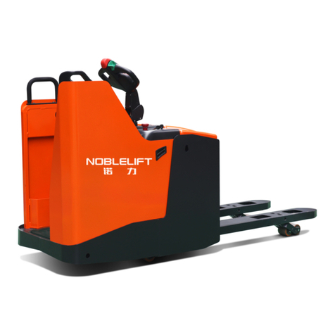
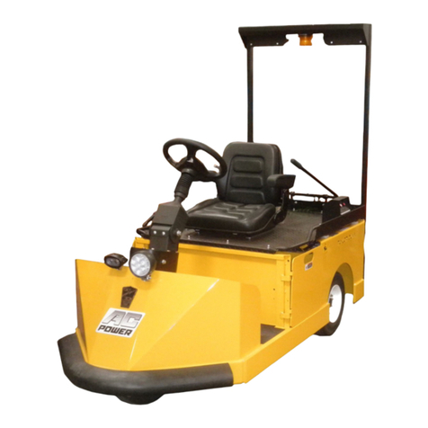
BT Ergomover 620 AC-TT User manual

© BT Industries AB
Valid only for serial number:
BT Products AB
S-595 81 MJÖLBY SWEDEN
Operator’s Manual GB
WARNING!
Do not use the truck before
first reading through the
OPERATOR’S MANUAL.
NOTE!
Keep for future reference.
Ergomover 620 AC-TT
Valid from serial number: 3000AI-
Order number: 212908-040
Issued: 2003-04-16 ITS

© BT Industries AB 212908-040
1
It is important that you read this
Operator’s Manual for your own
safety!
Before you start to use this truck it is of extreme importance that
you have read the contents of the entire Operator’s Manual to
be able to use the truck in a safe and efficient manner.
This Operator’s Manual contains information on how you should
use the truck, safety regulations and how to keep the truck in a
safe condition by following daily service routines.
Always follow the warnings given in this Operator’s Manual and
on the truck to avoid accidents and incidents from occurring.
BT Products AB

© BT Industries AB 212908-040
2
Table of Contents
Safety regulations ............................................................................... 3
Warning symbols .............................................................................. 3
General safety regulations ................................................................ 4
Warning and information plates and symbols ................................. 6
Presentation of the truck ................................................................... 7
Intended application of the truck ....................................................... 7
Forbidden application of the truck .................................................... 7
Truck data ........................................................................................ 7
Truck dimensions ............................................................................. 8
Identification plate ............................................................................ 8
Main components ............................................................................... 9
Controls and instruments ................................................................ 10
Control panel .................................................................................. 10
Troubleshooting .............................................................................. 12
Driving ............................................................................................... 13
Control ............................................................................................ 13
Starting the truck ............................................................................ 14
Braking and changing the
direction of travel ............................................................................ 14
Parking the truck ............................................................................. 14
Automatic parking brake ................................................................. 14
Emergency brake ........................................................................... 15
Battery ............................................................................................... 16
Valve-vented traction batteries ....................................................... 16
Liquid-filled traction batteries .......................................................... 16
Charging the battery ....................................................................... 16
Cleaning ......................................................................................... 17
Changing the battery ...................................................................... 17
Laddbord ........................................................................................ 18
Maintenance ...................................................................................... 21
Cleaning and washing .................................................................... 22
Transporting and storing the truck ................................................. 24
Lifting the truck ............................................................................... 24
Storing the truck ............................................................................. 24
Starting after a period of disuse ...................................................... 24
Recycling/discarding ........................................................................ 25
Discarding the battery ..................................................................... 25
Scrapping the truck ......................................................................... 25

Safety regulations
© BT Industries AB 212908-040
3
Safety regulations
Warning symbols
Always follow the warnings given in this Operator’s Manual
and on the truck to avoid accidents and incidents from occur-
ring.
Warning levels
Warning texts regarding safety provide information on the risks,
describe the consequences and instruct how to avoid accidents.
WARNING!
Warns that accidents can occur if the instructions are not fol-
lowed.
The consequences are serious personal injury or possibly
death and/or large material damage.
NOTE!
Marks the risk of a crash/breakdown if the instructions are not
followed.
Ordinance symbols
SAFETY SHOES
When the directive for safety shoes is given, safety shoes
must always be worn to avoid personal injury.
PROTECTIVE GLASSES
When the directive for protective glasses is given, protective
glasses must always be worn to avoid personal injury.

Safety regulations
© BT Industries AB 212908-040
4
General safety regulations
Always carry out daily service before the truck is used, see
chapter
Daily service and function checks
. The working order of
all safety equipment, guards and safety switches should be
checked before you use the truck. Such safety equipment must
not be disengaged or removed.
The battery must be secured in its intended compartment. The
battery shall have a weight that corresponds with the information
stated on the truck’s identification plate.
The truck must not be used if it is damaged or has faults that
affect safety or its safe use. The truck may not be used if it has
been repaired, modified or adjusted unless it has been checked
and approved by personnel authorised by BT.
Operating the truck
The truck is designed and produced to be your tool when trans-
porting, collecting and leaving loads.
If the truck is to be used in cold storage rooms the truck must be
especially built for this type of use.
It is not permitted to use the truck for purposes that it has not
been designed and produced for, e.g. the following applications:
- In areas where the atmosphere contains dust or gases
that can cause fires or explosions.
- To tow other trucks.
- To transport/lift passengers.
Personal protective equipment
• Always wear safety shoes with steel toe caps when using the
truck.
Fire
In the event of fire, use a powder fire extinguisher for electrical
materials (type ABE, Class I).
Operator’s responsibility
• The truck shall only be driven with care, good judgement and
in a responsible manner.
• Only handle loads that are stable and arranged in a safe
manner.

Warning and information plates and symbols
© BT Industries AB 212908-040
6
Warning and information
plates and symbols
The figure shows the position and significance of the plates and
symbols located on the truck.
1. Identification plate
2. Signal/Horn
3. Travel direction selector
1
2
3
Manufacturer:
Helge Nyberg AB
Industrigatan 2
SE-523 90 Ulricehamn, Sweden
BT ERGOMOVER 600 AC-TT
Year of manufacture: 2003
AB
CD
E
F
(See “Operator’s Manual”)

Presentation of the truck
© BT Industries AB 212908-040
7
Presentation of the truck
This is a towing truck designed for internal light goods handling.
The truck is used to pull trolleys on which goods is loaded.
Thanks to the high level of manoeuvrability and flexibility, the
truck can be used just about anywhere where carts are used
today.
Model 620 AC-TT is a towing truck that can tow a maximum of
10 trolleys with a total load on the tow bar of F=180 N.
Intended application of the truck
The truck is designed for transporting goods indoors, in heated
premises with smooth floors.
Forbidden application of the
truck
The truck is designed for handling goods indoors. It is not per-
mitted to use the truck for other purposes including the following:
- To transport/lift passengers
- To be driven or stored outdoors or in cold premises
Truck data
The table provides information regarding some technical data,
which is of value with daily use of the truck.
Truck type 620 AC-TT
Rated capacity, kg 500
Travel speed, km/h 8
Gradient with rated load, % 10
Weight incl. batteries, 50Ah C5, kg 200
Continuous noise level, dB A 70
Full body vibration value, m/s21,5

Presentation of the truck
© BT Industries AB 212908-040
8
Truck dimensions
Identification plate
The illustration shows the identification plate used on the truck.
The truck’s dimensions and weight
(mm) 620 AC-TT
Width incl. bumper wheels 600
Length incl. bumper wheels 1415
Height 1100
Instep height 65
Floor clearance 40
Wheel base 765
Turning radius without load handler 1700
Turning radius with load handler 1900
Load handler, B x L 400 x 600
Item Text Unit
AMODEL
B SERIAL NO
C RATED CAPACITY kg
D MAXIMUM SPEED km/h
E BATTERY TYPE
F WEIGHT WITH BATTERIES kg
Manufacturer:
Helge Nyberg AB
Industrigatan 2
SE-523 90 Ulricehamn, Sweden
BT ERGOMOVER 600 AC-TT
Year of manufacture: 2003
AB
CD
E
F
(See “Operator’s Manual”)

Main components
© BT Industries AB 212908-040
9
Main components
Model 620 AC-TT
1. Control panel with steering wheel and control lever
2. Powerpack with removable front panel
3. Battery cassette
4. Lifting points
5. Safety switch (contact mat)
6. Tow bar
1
2
3
4
4
5
6

Controls and instruments
© BT Industries AB 212908-040
10
Controls and instruments
Control panel
1. Steering wheel
2. Master key
3. Horn button
4. Handrail
5. Control lever
6. Combi instrument
7. Key switch
8. Master switch
1
2
3
4
5
6
7
0
I
8

Controls and instruments
© BT Industries AB 212908-040
11
Steering wheel (1)
The steering wheel is located to the left when the driver is stand-
ing in the truck.
Master key (2)
• Insert the master key in the master switch (8) situated on the
inside of the chassis where the operator stands on the truck.
Horn button (3)
The horn sounds as long as the button is pressed.
Handrail (4)
• For added support and to promote safe driving, let the right
hand rest on the handrail while driving.
Control lever (5)
The control lever controls speed and motor brake (reversing).
• Move the control lever forwards for driving, and backwards to
brake the truck.
Combi instrument (6)
The combi instrument displays the hour counter, battery indica-
tor and error codes. When the master key switch or the key
switch is switched on, all three LEDs (green, yellow and red)
light briefly, and subsequently only the green LED continues to
light - the display shows the number of hours power has been
switched on. The LEDs then start blinking - the display shows
the number of hours the truck has been driven. After this, the
yellow LED lights - the display shows the remaining battery
capacity as a percentage (%). The batteries should be
recharged when the capacity falls to 10%.
Key switch (7)
• First switch on the master switch, then start the truck using
the key.
Please note that the key switch only disconnects operating cur-
rent and not the battery power supply.

Controls and instruments
© BT Industries AB 212908-040
12
Master switch (8)
The master switch is located on the inside of the chassis when
the driver is standing in the truck.
Troubleshooting
If the truck appears to lack power or if it fails to start, proceed as
follows:
1. Make sure that the key switch is in postion Iand that the
safety switch/contact mat is pressed down by the operator. If
the safety switch/contact mat is pressed down and the bat-
tery indicator is lit but the truck still fails to start, check that
the electric cables to the safety switch/contact mat has not
been loose or damaged.
2. Check the battery voltage. If the battery indicator shows less
than 10% capacity, the batteries should be charged. With a
very low battery voltage, the truck can only be driven at 3
km/h. This occurs when the battery capacity is less than 2%.
If the power is switched off in this state, please wait 3-5 min-
utes before driving the truck again. Do not park the truck
with poorly charged batteries since this could cause damage
to the batteries.
3. Remove the keys from the key switch and the master switch
and open the battery cover. Check that the battery cable ter-
minals are firmly in contact with the battery posts and that
the cables are not damaged.
4. Check the battery fuse. If it has blown, the reason must
always be determined before a new fuse is fitted. It will blow
only if a short circuit has occurred in the cables or connec-
tors.
5. Check the control lever for damage or loose electrical
cables. Adjustments may only be done by an authorized
service technician!
6. The parking brake is not released even though the control
lever is activated and the safety switch/contact mat is
pressed down. If the parking brake is not energized, it will
immediately be applied. Check that none of the cables to the
brake is broken or damaged. Check that there is power at
the brake at startup and with the safety switch/contact mat
activated. If there is current, the brake itself is faulty and
must be replaced.
7. If the above checks do not reveal any defects but the truck
still fails to perform normally, the fault may be in the electron-
ics. The electronics are a reliable part of the truck, but they
are also sensitive and demand special knowledge for adjust-
ments or repairs. If the electronics are suspected of being
faulty, get in touch with our Service Department for informa-
tion of how to proceed.

Driving
© BT Industries AB 212908-040
13
Driving
The key switch and the master key are important to the operator
and to safety. The key switch is provided to a unique key to pre-
vent unauthorized use of the truck. Note that the key switch only
disconnects the operating current for motor control and applies
the parking brake.
The master key disconnects battery power (the battery indicator
goes out when one of the key switches is switched off).
Model 620 AC-TT
The load should be uniformly distributed on the trolley/trolleys
and firmly secured so that it will not fall off or throw about while
driving. The trolleys used must conform to the BTs technical
specifications.
Hitching trolleys:
- Reverse the truck up to the trolley.
- Turn the key switch to 0to prevent unintentional move-
ment of the truck.
- Connect the trolley to the truck.
- Ensure that the connecting device is properly locked.
WARNING!
Exercise maximum care when towing trolleys.
With a heavy load, braking suddenly while turning may cause
the trolley and truck to turn over!
Control
The pedal/contact mat on the floor in the driver compartment
serves as a safety switch and must be pressed down to enable
the truck to be used, see picture in chapter
Main components.
This prevents inadvertent starting.
The truck is manoeuvred by means of the steering wheel and a
control lever which controls speed and motor brake (reversing).
The control lever is moved forwards to drive the truck forwards,
and backwards to brake the truck.
If the pedal/contact mat is released, the parking brake operates
automatically. Continuing to move the control lever backwards
from the neutral position causes the truck to reverse. Moving the
control lever forwards again operates the brake during revers-
ing.

Driving
© BT Industries AB 212908-040
14
Starting the truck
• Insert the master key and turn it.
• Insert the key in the key switch and turn it.
• Press down the pedal/contact mat and keep it constantly
pressed down while driving.
• Move the control lever forwards and drive the truck smoothly
to preserve the batteries, to reduce wear and to ensure
safety.
• Drive carefully over thresholds and major surface irregulari-
ties.
Braking and changing the
direction of travel
• Brake (reverse motor) by moving the control lever backwards
until the truck stops. If you continue to hold the control lever in
the rearward position the truck will begin to reverse. Take
care when reversing.
Parking the truck
Before leaving the truck, make sure that the truck is stationary
and the automatic parking brake has been applied (a "click" is
heard).
• After parking the truck, always remove the keys from the key
switch and from the master switch. If the truck is left station-
ary with the battery power switched on, the batteries may be
discharged and could sustain serious damage.
• Always remove the key from the key switch to prevent unau-
thorized persons from driving the truck.
Automatic parking brake
The motor is equipped with an electromagnetic parking brake.
This operates as soon as the pedal/contact mat is released. The
parking brake is capable of keeping the truck stationary on any
gradient that the truck can climb.
The parking brake is delayed briefly before it is applied, in order
to avoid a jerky stop. The delay is preset at the factory and must
not be altered, since it may be dangerous if the delay time is too
long.

Driving
© BT Industries AB 212908-040
15
Emergency brake
If motor brake should fail, the parking brake can be activated by
switching the master key to 0.
WARNING!
Risk of being thrown forward onto the control panel.
If the master key is switched to 0 while the truck is travelling at
high speed, the truck will jerk violently.
This way of applying the brake should be used only in emer-
gency situations.

Battery
© BT Industries AB 212908-040
16
Battery
The truck is equipped with two 12 V batteries connected in
series.
Valve-vented traction batteries
The truck is equipped as standard with valve-vented traction bat-
teries. These are maintenance-free, since they need not be
topped up at any stage during their life cycle.
The distinctive features of these batteries include:
• they are intended for electric vehicles
-traction
• the electrolyte is in solid form
- no liquid can leak out of the battery, not even if the battery
case should break
• closed cell with safety valve
- no topping up with liquid is necessary
- very low gas emission
Liquid-filled traction batteries
We do not recommend the use of liquid-filled batteries, in order
to avoid the spillage of acid which is aggressive and may cause
corrosion damage.
If liquid-filled batteries still are used, the electrolyte level should
be checked at regular intervals, and the batteries should be
topped up with distilled water when necessary. In addition, the
electrolyte density should be regularly checked.
NOTE! Ordinary car batteries must never be used. These are
not intended for powering electric vehicles.
Charging the battery
The truck is equipped with an external charger.
It is important to use a charger recommended by us for the bat-
teries that are being used.
Before charging, the keys must always be removed from the key
switch and from the master switch.

Battery
© BT Industries AB 212908-040
17
• Arrange a parking place where an earthed 220 V wall socket
is available and where it is suitable to leave the truck parked
at the end of the working day. Also make arrangements in this
place for accommodating the maintenance materials and
spares.
• Remove the master key.
• Connect the charger to an earthed 220 V wall socket. The
charger will charge the batteries automatically and will then
switch over to trickle charging as long as the charger is con-
nected.
NOTE: If the batteries have been entirely discharged, it is impor-
tant to recharge them immediately.
New batteries must be discharged and recharged about
20 times before they achieve full capacity.
NOTE!
Always follow your local industrial safety regulations for lead-
acid batteries. In addition, your factories inspector should
approve the battery charging station.
Cleaning
• Keep the batteries clean, and remove any dirt and oxides.
Leakage current may occur on a dirty battery.
Changing the battery
The batteries stand on a removable battery cassette. Before
changing the batteries, always remove the key from the master
switch.
Procedure:
• Release the catch through the holes at the front of the cas-
sette and push in. The lock will be released and the cassette
can then be withdrawn.
NOTE! A battery cassette weighs up to 65 kg. So arrange a low
table next to the truck to enable the battery cassette to be trans-
ferred quickly onto this table.
• Slacken off the battery cable clips. Note how the battery
cables are connected.
• Disconnect both cable clips from one battery at a time (raise
the plastic cover and lift off the clip).

Battery
© BT Industries AB 212908-040
18
• Change the batteries ans replace the clips. Red is the posi-
tive pole (+) and blue is the negative pole (-). Repeat the pro-
cedure with the next battery.
NOTE! Make sure that the short separate cable runs from the
positive pole (+) on one of the batteries to the negative pole (-)
on the other.
• When the cassette is slid back into the powerpack, ensure
that the lock has closed. Check that the cassette cannot be
pulled out.
WARNING!
The battery poles must not be short-circuited by any object
made of metal or other conductive material, since the battery
could then explode and cause serious damage and injuries.
Charging table
Placement of the charging table and the
STOP sticker
The U profile is supplied separately from Europfil (it is not sup-
plied together with the truck).
1. Place the U profile on the floor.
2. Align the charging table with the U profile.
3. Drive the truck to the charging table
4. Align the STOP sticker with the yellow marking on the truck
and attach it.

Battery
© BT Industries AB 212908-040
19
Charging from the other side of the truck aisle
• Loosen the charging table plate, rotate it 180°, and secure the
plate again.
• Move the battery charger to the other side of the charging
table. Remove the yellow sticker on the truck and attach the
extra sticker on the other side of the truck. (The extra yellow
sticker is included in the delivery of the truck.)

Battery
© BT Industries AB 212908-040
20
Table of contents
Other BT Truck manuals
Popular Truck manuals by other brands

Chevrolet
Chevrolet HM80 Series Service manual

DAF
DAF LF45 Series Maintenance schedule

PFAFF silberblau
PFAFF silberblau SILVERLINE HU 20-115 BTS operating instructions

freightliner
freightliner PT126SLP Maintenance manual

Jacobsen
Jacobsen SV 3422 Gas Operator's manual

Komatsu
Komatsu 830E-1AC Operation & maintenance manual