manuals.online logo
Brands
  1. Home
  2. •
  3. Brands
  4. •
  5. Dahlia
  6. •
  7. Indoor Furnishing
  8. •
  9. Dahlia YO888 User manual

Dahlia YO888 User manual

Dimensions
Width - 57cm
Depth - 28.5cm
Height - 96.5cm
Important– Please read these instructions fully before starting assembly
Assembly Instructions- please keep for future reference
Issue 1 - 12/12/17
Storage Unit
YO888
464/3944
1
Safety and Care Advice
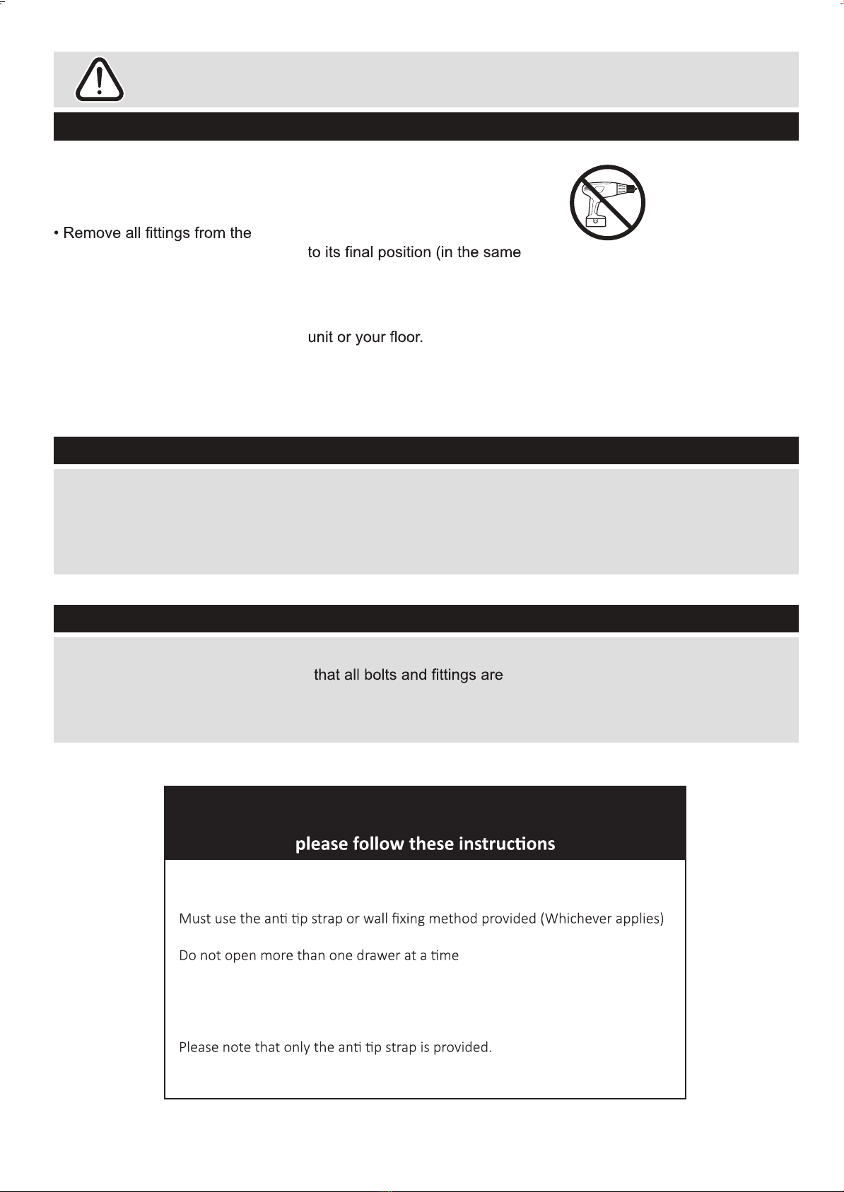
Important – Please read these instructions fully before starting assembly
• Check you have all the
components and tools listed on
page 2
plastic bags and separate them
into their groups.
• Keep children and animals
away from the work area, small
parts could choke if swallowed.
• Make sure you have enough
space to layout the parts before
starting.
• During assembly do not stand
or put weight on the product,
this could cause damage.
•Assemble the item as close
room) as possible.
•Assemble on a soft level
surface to avoid damaging the
• Parts of the assembly will be
easier with 2 people.
• Only clean using a damp cloth
and mild detergent, do no use
bleach or abrasive cleaners.
• From time to time check that
there are no loose screws on
this unit.
•This product should not be
discarded with household waste.
Take to your local authority
waste disposal centre.
Care and maintenance
•Assemble all parts and bolts
loosely during assembly, only
once the product is complete
should you fully tighten the bolts
• Regularly check and ensure
tightend properly.
Handy Hints
• We do not
recommend the use
of power drill/drivers
for inserting screws,
as this could damage
the using. Only use hand
screwdrivers
WARNING
In order to help prevent overturning –
To help prevent product toppling over please follow the below steps:-
Do not allow children to climb or hang on the furniture
Do not place heavy items in the top drawers
Do not place heavy items on top of the furniture, unless the furniture has been
designed for this purpose
You will need to provide wall plugs and screws applicable for your wall type
2
Components -Panels
Please check you have all the panels listed below
123
4 5 6
9
8
7
Left Side Panel x 1
(80(w) x 26.5(d)cm)
Middle Left Panel x 1
(80(w) x 26.5(d) cm)
Right Side Panel x 1
(80(w) x 26.5(d) cm)
Middle Right Panel x 1
(80(w) x 26.5(d) cm)
Top Panel x 1 Base Panel x 1
Open Shelves x 4
(24.7(w) x 15(d) cm)
Door Panel x 1
(83(w) x 24(d) cm)
Adjustable Shelves x 2
(24(w) x 21(d) cm)
12
11
10 Side Back Panels x 2
(80.5(w) x 15.5(d) cm)
Central Back Panel x 1
(80.5(w) x 21.5(d) cm)
Legs x 4
(13(w) x 10(d) cm)
(57(w) x 26.5(d)cm) (57(w) x 26.5(d)cm)
Tools required
Phillips screwdriver
(medium & large)
Ruler – Use this ruler to help correctly identify the screws
0 5 10 15 20 25 30 35 40 45 50 55 60 65 70 75 80 85 90 95 100 110 115 120 125 130 135 140 145 150 155 160 165 170
105
Components - Fittings
Note:
may be supplied than are required.
3
Male Camlocks x 24 Female Camlocks x 24 30mm Dowel x 8 Shelf Supports x 8
35mm Screw x 8 12mm Screw x 9 Push Catch x 1
14mm Screw x 24 14mm Screw x 16
J K L
MN
18mm Screw x 1
Hinges x 2 Catch Plate x 1
Panel Stiffeners x 12 Wall Strap x 1
4
5
Assembly Instructions
Step 1
Step 2
1. Into Left Side Panel 1
insert a total of 4 x Male
Camlocks B as shown.
2. Locate 2 x Open Shelves
7 onto Male Camlocks
3. Into holes shown in Side
Panels 7 Insert
4 x Female Camlocks
as shown. Use a
screwdriver to turn the
Female Camlocks
Clockwise to lock
For more information refer
to the Using Camlocks
Section
A
1
7
7
2
1
7
7
1
7
7
B
1. Into Middle Left Panel 2
insert a total of 4 x Male
Camlocks B as shown.
2. Locate 2 x Open Shelves
7 onto Male Camlocks
3. Into holes shown in Side
Panels 7 Insert
4 x Female Camlocks
as shown. Use a
screwdriver to turn the
Female Camlocks
Clockwise to lock
For more information refer
to the Using Camlocks
Section
2
A
7
7
B
6
Assembly Instructions
Step 3
Step 4
.
7
7
7
7
3
4
3
1. Into Right Side Panel 3
insert a total of 4 x Male
Camlocks B as shown.
2. Locate 2 x Open Shelves
7 onto Male Camlocks
3. Into holes shown in Side
Panels 7 Insert
4 x Female Camlocks
as shown. Use a
screwdriver to turn the
Female Camlocks
Clockwise to lock
For more information refer
to the Using Camlocks
Section
3
A
7
7
B
1. Into Middle Right Panel
insert a total of 4 x Male
Camlocks B as shown.
2. Locate 2 x Open Shelves
7 onto Male Camlocks
3. Into holes shown in Side
Panels 7 Insert
4 x Female Camlocks
as shown. Use a
screwdriver to turn the
Female Camlocks
Clockwise to lock
For more information refer
to the Using Camlocks
Section
4
A
7
7
B
Assembly Instructions
Step 5
7
1. Into the ends of Panels
1 2 3 and 4 insert
a total of 8 x Dowels C
as shown.
2. Locate Base Panel 6
onto Dowels
3. Connect Panel 6 using
8 x Screws E as shown
Step 6
1. Connect 4 x Legs 12
to Base Panel 6 using
6 x Screw J per Leg
1
2
3
4
6
6
J
1
12
12
12
12
J
J
J
J
J
J
J
1234
C
6
6
E
6
J
12
8
Assembly Instructions
Step 7
Step 8
1. To Top Panel 5 install
Push Catch G using
4 x Screw K
G
K
5
K
K
K
5
1
2
3
4
10
11
10
5
K
1. Into the underside of Top
Panel 5 install 8 x Male
Camlocks A as shown
2. Slide Back Panels 11
and 2 x 10 into Position
3. Locate Top Panel 5
onto Panels
and
4. Into holes shown in
Panels 1 2 3 and 4
Insert 8 x Female
Camlocks
as shown. Use a
screwdriver to turn the
Female Camlocks
Clockwise to lock
For more information refer
to the Using Camlocks
A
5
11
10
5
123
4
1234
B
9
Assembly Instructions
Step 9
Step 10
1. On the reverse of the unit
install a total of 12 x Panel
Stiffeners as shown
using 12 x Screws k
M5
3
11
10
10
K
M
K
M
K
MK
M
K
M
K
M
K
M
K
M
K
M
K
M
K
M
K
M
5
L
2
3
9
8
9
K
1. Connect Catch Plate
L to Door 8 using
1 x Screw F
2. Connect Doors 8 to
Panel 2 as shown
using a total of 4 x Screw
F per Hinge
3. Insert 8 x Shelf
Supports into holes
shown
4. Place 2 x Shelves 9
onto Shelf Supports
L8
F
8
2
F
D
9
10
Assembly Instructions
Step 11
1
5
N
The unit is floor
standing, but it is
recommended that the
unit is secured to the
wall.
1. Move the unit into
desired position.
2. Mark the wall with a
suitable scribe the
position of the fixing
hole.
3. Drill hole and insert a
suitable Wall Plug,
Please check the type of wall
you are fixing to and for more
information please see the
guide to wall mounting
& Fixings on the back page
Warning:
Before driling,check
wall for hidden pipes
and cables.
4. Secure the strap to the
wall using a suitable
wall screw
Note: To hide the straps
behind the unit, drill the
holes lower than the top of
the unit
1. To Top Panel 1 fit
1 x Wall strap L as
shown using 1 x Screw
5
NH
Assembly Complete

Popular Indoor Furnishing manuals by other brands

Living Spaces 255019 Assembly instructions

Living Spaces

Living Spaces 255019 Assembly instructions

DURAVIT LM 7874 Mounting instructions

DURAVIT

DURAVIT LM 7874 Mounting instructions

Axor Citterio 39136XX1 installation instructions

Axor

Axor Citterio 39136XX1 installation instructions

Songmics VASAGLE LCT065 Assembly instructions

Songmics

Songmics VASAGLE LCT065 Assembly instructions

First Office intermix Assembly instructions

First Office

First Office intermix Assembly instructions

Openbox BMU 39 Assembly instructions

Openbox

Openbox BMU 39 Assembly instructions

Direct Wicker TURIN ROUND Assembly instructions

Direct Wicker

Direct Wicker TURIN ROUND Assembly instructions

Cohesion XP Series instructions

Cohesion

Cohesion XP Series instructions

URBAN OUTFITTERS SILAS Assembly instructions

URBAN OUTFITTERS

URBAN OUTFITTERS SILAS Assembly instructions

Rauch M1734 Assembly instructions

Rauch

Rauch M1734 Assembly instructions

Manhattan Comfort UTOPIA 53.14 Assembly instructions

Manhattan Comfort

Manhattan Comfort UTOPIA 53.14 Assembly instructions

SureShade ATF-SG installation instructions

SureShade

SureShade ATF-SG installation instructions

Royal garden MLOSCH201 Assembly instructions

Royal garden

Royal garden MLOSCH201 Assembly instructions

Coaster 800215 Assembly instruction

Coaster

Coaster 800215 Assembly instruction

Next 950401 Assembly instructions

Next

Next 950401 Assembly instructions

LuxaFlex PowerView quick start guide

LuxaFlex

LuxaFlex PowerView quick start guide

CABINETS TO GO Findley & Myers WD2442 Assembly instructions

CABINETS TO GO

CABINETS TO GO Findley & Myers WD2442 Assembly instructions

VITRA Alcove Cabin Instructions for use

VITRA

VITRA Alcove Cabin Instructions for use

manuals.online logo
manuals.online logoBrands
  • About & Mission
  • Contact us
  • Privacy Policy
  • Terms and Conditions

Copyright 2025 Manuals.Online. All Rights Reserved.