manuals.online logo
Brands
  1. Home
  2. •
  3. Brands
  4. •
  5. Dahua
  6. •
  7. Power Supply
  8. •
  9. Dahua DH1715A User manual

Dahua DH1715A User manual

Popular Power Supply manuals by other brands

Videx 520MR Installation instruction

Videx

Videx 520MR Installation instruction

Poppstar 1008821 Instructions for use

Poppstar

Poppstar 1008821 Instructions for use

TDK-Lambda LZS-A1000-3 Installation, operation and maintenance manual

TDK-Lambda

TDK-Lambda LZS-A1000-3 Installation, operation and maintenance manual

TDK-Lambda 500A instruction manual

TDK-Lambda

TDK-Lambda 500A instruction manual

Calira EVS 17/07-DS/IU operating instructions

Calira

Calira EVS 17/07-DS/IU operating instructions

Monacor PS-12CCD instruction manual

Monacor

Monacor PS-12CCD instruction manual

VOLTIMA MagicBox 15 Installation and operating instructions

VOLTIMA

VOLTIMA MagicBox 15 Installation and operating instructions

Miller Auto Deltaweld 452 owner's manual

Miller

Miller Auto Deltaweld 452 owner's manual

BCP PUOUBK How to install

BCP

BCP PUOUBK How to install

HC 2210 manual

HC

HC 2210 manual

Agilent Technologies 6032A Service manual

Agilent Technologies

Agilent Technologies 6032A Service manual

Radial Engineering SB-48UB user guide

Radial Engineering

Radial Engineering SB-48UB user guide

Puls CT5.241 installation manual

Puls

Puls CT5.241 installation manual

OCZ ZX1250W Technical specifications

OCZ

OCZ ZX1250W Technical specifications

iseg ECH 238 manual

iseg

iseg ECH 238 manual

Agilent Technologies 6631B Service manual

Agilent Technologies

Agilent Technologies 6631B Service manual

Power XXL A Series instruction manual

Power

Power XXL A Series instruction manual

HP 6200B Operating and service manual

HP

HP 6200B Operating and service manual

manuals.online logo
manuals.online logoBrands
  • About & Mission
  • Contact us
  • Privacy Policy
  • Terms and Conditions

Copyright 2025 Manuals.Online. All Rights Reserved.

1
Model
Model
Model
Model
DH1715A
DH1715A
DH1715A
DH1715A
Dual
Dual
Dual
Dual
-
-
-
-
Channel
Channel
Channel
Channel
Regulated
Regulated
Regulated
Regulated
Voltage/Current
Voltage/Current
Voltage/Current
Voltage/Current
Power
Power
Power
Power
Supply
Supply
Supply
Supply
User
User
User
User
’
’
’
’
s
s
s
s
Manual
Manual
Manual
Manual
Da
Da
Da
Da
h
h
h
h
ua
ua
ua
ua
Company
Company
Company
Company
of
of
of
of
Electronic
Electronic
Electronic
Electronic
Instrument
Instrument
Instrument
Instrument
in
in
in
in
Beijing
Beijing
Beijing
Beijing
2
CONTENTS
CONTENTS
CONTENTS
CONTENTS
Description
Description
Description
Description
1. Operating Features
2. Operating Principle
3.
Structure Features
4.
Applications
5.
Maintenance
6.
Completeness of the Instrument
7.
Storage
8.
Guarantee
3
DESCRIPTION
DESCRIPTION
DESCRIPTION
DESCRIPTION
The Model DH1715A Dual - Channel Regulated V oltage/Current Power Supply is an
automatic switching type of high accuracy CV/CC power supply with a 3
1/2
digits display
meter on the front panel.
The output voltage and the output current can be displayed by ON /OFF switch on the front
panel.
This instrument provides a preset circuit and an output switching circuit, the output switch is
an electronic type, which does not generate chattering and noise. When the output switch is
set to “ OFF ” state, the value indicated by the output voltmeter cor responds to the position of
the voltage setting knob so as to preset the voltage.
Press “ OUTPUT ” switch, the output voltage is available from “ OUTPUT ” terminal.
This instrument has function of the remote-controlled voltage. The input socket on the rear
panel is controlled remotely.
Please carefully read this instruction manual before use the power supply.
1.
1.
1.
1.
OPE
OPE
OPE
OPE
R
R
R
R
ATING
ATING
ATING
ATING
FEATURES
FEATURES
FEATURES
FEATURES
Mode l
DH1715A-3
32V-2A
DH1715A-5
32V-3A
INPUT
Input P ower S upply
2 2 0V ±10% 50Hz ±5%
P ower D issipation (200VAC), R ate L oad
≤
300VA
OUTPUT
O utput
Vo
ltage (10-turn)
0-32V
T heor eti cal
V
alue of
V
oltage resolution
5mV
O utput C urrent(1-turn)
0-2A
0-3A
CV FEATURE
Adj. Ratio
S ource E ffect (line regulation)(for 0-100%
change of output current)
1×10
-5
+1mV
L oad E ffect
1×10
-5
+2mV
R ipple and N oise(5Hz-1MHz) r.m.s
1mV
Typ
e
.
Value
of Temp. Coe.
2× 10
-4
℃
R emote C ontrol ( C on trol
V
ol t.
/
O utput
V
ol
t
.)
about 10V/32V
CC FEATURE
Adj. Ratio
Source Effect (line regulation)(for ±10%
change of line volt)
2mA
L oad E ffect(load regulation) (for 0-100%
chang e of load resistance)
10mA
R ipple and N oise (5Hz-1mHz) r.m.s
1mA
R emote C ontrol ( C on.
Voltage/
Output C u r rent)
about 10V/2A 10V/3A
CV Mode
I
ndication
CC M ode
I
ndication
Operating
T
emperature Rang
0-40 ℃
R elative A mbient O perating H umidity R ange
20-90%RH
S torage
T
emperature and H umidity R ange
unforced air cooling
C ooling M ethod
positive or negative grounded
P olarity of O utput
V
oltage
4
Continue:
2.
2.
2.
2.
OPE
OPE
OPE
OPE
R
R
R
R
ATING
ATING
ATING
ATING
PRINCIPLE
PRINCIPLE
PRINCIPLE
PRINCIPLE
The feature of this power supply is that the output voltage signal of constant V oltage circuit
and the output current signal of constant current circuit both are applied to the “ GATE ”
circuit at the same time. According to requirement of the load, the pow er supply is
determined to operate in the CV mode or in the CC mode, the automatic switching of the
regulated voltage and the regulated current can solve the problems of over — current
protection of the regulated power supply and the over — voltage protection of the regulated
current power supply.
CONTROL
CONTROL
CONTROL
CONTROL
CIRCUIT:
CIRCUIT:
CIRCUIT:
CIRCUIT:
It is an adjustable reference voltage generator. The output current
and voltage depend on setting the reference voltage.
Model
DH1715A-3
32V-2A
DH1715A-5
32V-3A
DC
VOLTMETER
Range Selection
Accuracy of V oltmeter
±(0.5%rdg + 3dgts, at 20 ± 2 ℃ and < 80%RH
Maximum Allowable Application
Voltage
DC AMMETER
Full Scale (Fixed Range)
Ammeter Accuracy(at20 ± 2 ℃ and<80%RH)
±1rdg + 5dgts
Temperature Coe
.
(+400 ×10
-6
)/ ℃ full- scale + the accuracy mentioned
above
Zero Drift
Not greater than 3dgts within 0-40 ℃
Input Fuse
2A
Output Fuse
Weight
≤8kg
External Dimensions
305(L) ×200(W) ×170(H)mm
Reliability of the Instrument
MTBF ( θ)≥5000 hours
Remote
Control
Signal
Transformer
Relay Switching and
Aux. Supply Circuit
Output Switch Circuit
Reference
Voltage
DC
Remote
Control
Circuit
Voltage
Sampling
Control
Circuit
Rectify
and Filting
Series
Setting
Amplify
Gate
-
CC
Diff
Ampl
+
-
CV
Diff.
Ampl
+
A/D
Conv
AC
220V
Meter Circuit
Current
Sampling
Figure 1
5
2.1
2.1
2.1
2.1
Description
Description
Description
Description
of
of
of
of
Constant
Constant
Constant
Constant
-
-
-
-
Voltage
Voltage
Voltage
Voltage
Mode
Mode
Mode
Mode
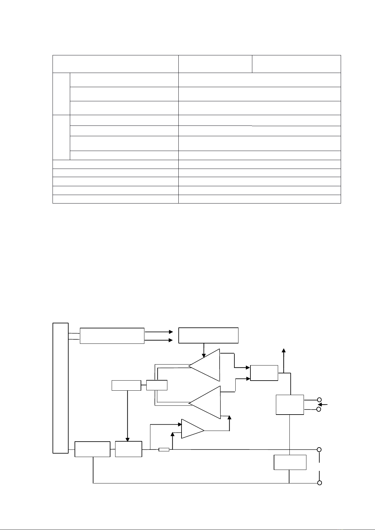
The reference output voltage circuit is applied to the negative input terminal of a CV error
amplifier, the error voltage from the voltage sampling resistor is applied to the positive input
terminal of the CV error amplifier. The error signals of both vol tages are compared each
other and via the gate circuit by amplify then applied to the base of a regulated tube. The
base current of the regulator tube is changed, then a stabilized output voltage can be obtained ,
the adjustment of the output voltage is re alized by setting the voltage potentiometer on the
front panel.
2.2
2.2
2.2
2.2
Description
Description
Description
Description
of
of
of
of
Constant
Constant
Constant
Constant
-
-
-
-
Current
Current
Current
Current
Mode
Mode
Mode
Mode
The reference voltage from the control circuit is applied to the negative input terminal of a
CC error amplifier, the current signal from A/V conversion is applied to the positive input
terminal of the CC error amplifier. Both signals are compared each other and then amplified
to control the base voltage of the regulator tube to reach a stable current output.
2.3
2.3
2.3
2.3
CV/CC
CV/CC
CV/CC
CV/CC
Conversion
Conversion
Conversion
Conversion
-
-
-
-
CV
CV
CV
CV
mode
mode
mode
mode
into
into
into
into
CC
CC
CC
CC
mode
mode
mode
mode
Setting CC potentiometer, a preset current value is provided as required, the resistor load is
reduced, the output current is increased. When the output current reaches the preset constant -
current value, the output voltage is reduced. When the power supp ly is power supply is
operating in the constant - current mode, even of the resistor load value is reduced to zero ( in
short circuit state), the output current can not be increased, it always keeps pre - setting value
constantly; that means this instrument can automatically be converted from constant - voltage
mode to constant current mode so as to protect the load from over - current. It is an automatic
CV/CC crossover system type of power supply.
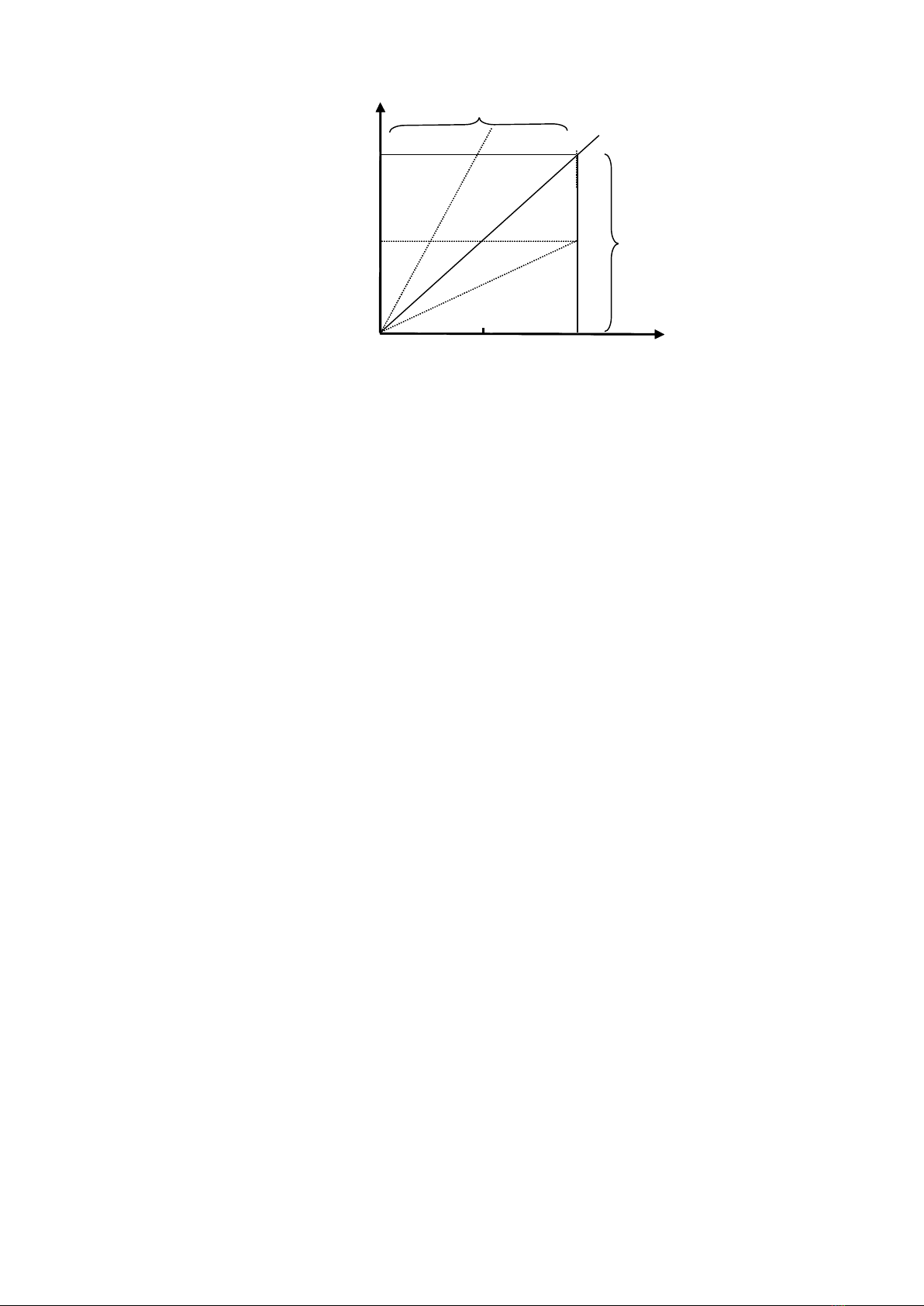
The Figure 2 shows operating points and operating domain related to the load lines. The
preset output voltage is
10V,
the limited current is 2A, the operating point in non--load is at
A
,
when RL=10 Ω
,
operating point B, and when RL=5 Ω , operating point is at C. The
operating point moves from C to D ,if the resistor load is reduced from RL=5 Ωto 2.5 Ω,the
instrument operation is changed from the constant-voltage domain into the constant — current
domain. Point C is called “ Crossover Point ” owing to change modes.
Wen
the resistor load
(RL) is 2.5 Ω , the output voltage is I. RL=2 × 2.5=5V.
2.4
2.4
2.4
2.4
CC/CV
CC/CV
CC/CV
CC/CV
Conversion-Constant
Conversion-Constant
Conversion-Constant
Conversion-Constant
Current
Current
Current
Current
Mode
Mode
Mode
Mode
into
into
into
into
Constant-Voltage
Constant-Voltage
Constant-Voltage
Constant-Voltage
Mode
Mode
Mode
Mode
Setting CV potentiometer, a preset value applied as required. When the output voltage
reaches the preset constant voltage value, then output current is reduced.
When the output current is 2A the resistor load is 0 Ω , operating point is E. While the resistor
load is increased to 2.5 Ω , the operating point moves from E to D. When the operating point
is increased to 5 Ω
,
the operating point moves from D to C. While the resistor load further is
increased to 10 Ω , the operating point moves from C to B. In this case, the instrument is
converted to the constant - voltage domain. When the resistor load is increased continuously
to an open circuit, the operating point moves from B to
A
. Generally, the voltage applied to
the load is not more than the preset voltage. The instrument can convert from the CC mode
to the
V
mode in order to protect the load. The point C serves as a crossover point.
6
2.5
2.5
2.5
2.5
Output
Output
Output
Output
Switching
Switching
Switching
Switching
Circuit
Circuit
Circuit
Circuit
This instrument provides a special output switch, the output voltage can be preset as required
before the switch is unpressed. After the voltage is adjusted, press the switch. This switch is
an uncontacted electricity type of switch so it does not generat
e
a mechanical spark,
protecting users
’
safety.
2.6
2.6
2.6
2.6
Digital
Digital
Digital
Digital
Display
Display
Display
Display
Model TY – 43 digital meter adopts LED digital tube as display unit. At least, one or two
digits generated by the display may flicker. It is not caused by the wareform or noise of
output, w hile by characteristics of the A/D convert o
r.
When there is no input voltage, the display will be recovered to zero automatically. When the
input voltage, is inverse, “ - ” polarity will be displayed automatically. When the operating
voltage is
5V,
its input sensitivity is DC ±199.9mV of full - scale.
3.
3.
3.
3.
STRUCTURE
STRUCTURE
STRUCTURE
STRUCTURE
FEATURES
FEATURES
FEATURES
FEATURES
The instrument is designed symmetrically between left and right on the front panel. On the
upper side, there are two digital meters.
A
switch for output in the middle of the panel is
mounted. There are four knobs in line as voltage potentiometer of each c ircuit, and current
setting potentiometers for each way. The two external sockets are mounted in the middle or
lower part of the panel and at the bottom of the panel there are a pair of output binding posts
and a screw grounded with a short bar. When “ + ” or “ - ” to ground is needed, we can connect
the short bar.
At the lowest bottom of the instrument
’
s back, there are one power cord and two pairs of
input sockets for the remote - control signal corresponding to the two ways on the front panel.
There are L/R (local/remote control) and V/C (voltage/current control) operating selector
switches, respectively. The input fuses both are mounted on the rear panel of the instrument.
4.
4.
4.
4.
APPLICATIONS
APPLICATIONS
APPLICATIONS
APPLICATIONS
4.1
4.1
4.1
4.1
Before operation, should check L/R (local/remote control) selector whether on its right
position or mot, otherwise it doesn ’ t operate, generally it is at
L
position.
4.2
4.2
4.2
4.2
Turn on the power supply, p ress the “ V ” button by adjusting the voltage setting
CC Mode
(RL<5 Ω )
I
0
2A
1A
5V
10V
E
0
E
D
C
B
A
RL=2.5 Ω
RL=5 Ω
Load Line
RL=10 Ω
Figure 2
7
potentiometer to a required voltage value and then press the “ OUTPUT ” button. While the
voltage is available at the binding post, at the moment, the constant - voltage mode starts
operating. If the voltage value drops, in this case the instrument is in constant - current Mode,
should set the CC setting potentiometer to the extreme position clockwise.
4.3
4.3
4.3
4.3
Preset a constant – current point and set the output current of the unit. By above,
mentioned method, after the constant - voltage point is set, press the “ A ” button and output
terminal is shorted, turn on the “ OUTPUT ” switch. After the current setting potentiometer is
set to the required value.
To
keep the voltage position, turn off the “ OUTPUT ” switch and remove the short
bar,
connect the 1oad, press the “ OUTPUT ” switch, the instrument provides the required current
and voltage for the load.
4.
4.
4.
4.
4
4
4
4
When turn off the power supply, first should turn off the “ OUTPUT ” switch, then turn off
the “ POWER ” switch.
4.5
4.5
4.5
4.5
Remote -Control CV Output
The output voltage can be controlled by an external voltage of 0 -
10V.
As the externa1 contro1 signal, its common termina1 is a “ + ” n output terminal.
4.5.1
4.5.1
4.5.1
4.5.1
Turn on the R/L (remote/loca1) selector switch to R position.
Turn on the V/C (voltage/current) selector switch to
V
position.
4.5.2
4.5.2
4.5.2
4.5.2
Turn on the “ POWER ” switch and the “ OUTPUT ” switch, the external control voltage
is applied through the jack on the rear panel of the unit. Adjust “ VOLTAGE ” switch of the
potentiometer to the extreme position clockwise, adjust the external control voltage so that
the output voltage becomes the desired voltage.
The relationships between the o u tput voltage (E o ) and the external control voltage
(El) is expressed as follows:
L
V
C
R
L
R
V
C
R
L
Lift
Voltage
Current
Remote
Local
Right
Voltage
Current
Remote
Local
Figure 3
8
Eo=1/10 E
max
. E
1
.a (V)
Where Em: Maximum rated voltage (V)
El: External control voltage signal (V)
0V
≤E
1
≤<l0V
Term αis factor of 0-l which depends on the “ voltage ” setting potentiomet e
r.
Factor is 1
when “ VOLTAGE ” voltage setting potentiometer is set to the extreme positions clockwise.
Factor is 0 when both potentiometers are set to the extreme positions counterclockwise. It is
used to select the ratio of the output voltage (Eo) with respect to the external control voltage
signal (E1). Norma1ly, it is adjusted to the maximum vo1tage.
NOTE
NOTE
NOTE
NOTE
1:
1:
1:
1:
The vo1tage of the common line of the external control voltage signa1
(El) becomes that of the “ + ” output terminal.
NOTE
NOTE
NOTE
NOTE
2:
2:
2:
2:
The input impedance across remote control input jack is approximately
20K Ω. The ripple may be amplified and conveyed to the output loop circuit.
NOTE
NOTE
NOTE
NOTE
3:
3:
3:
3:
To
feed the external control vo1tage signal, a shielded cab1e (or a pair of stranded
wires) is used and the shielding wire is connected to the “ + ” output terminal. When the
wiring distance is very long, should prove a full protection against noise.
NOTE
NOTE
NOTE
NOTE
4:
4:
4:
4:
When the R/L (r e mote/local) switch is thrown to the
L
position, the output voltage
can be control1ed with the voltage setting potentiometer manually on the front panel.
NOTE
NOTE
NOTE
NOTE
5:
5:
5:
5:
Make sure that the output voltage is within the rated output voltage of the
instrument.
4.6
4.6
4.6
4.6
Remote Control Constant -Current Mode
The output current can be controlled by the external contro1 voltage signal
4.6.1
4.6.1
4.6.1
4.6.1
Turn on the V/C (voltage/current) selector switch to C position.
4.6.2
4.6.2
4.6.2
4.6.2
The external control voltage signal is ap p lied to the “ INPUT ” jack which is
on the rear panel of the instrument. Please note the po1arities of “ + ” and “ - ” .
4.6.3
4.6.3
4.6.3
4.6.3
Throw the R/ L -switch to R (remote control) position.
4.6.4
4.6.4
4.6.4
4.6.4
Turn on the power supply and output switch, then the output terminal is shorted, set the
current setting potentiometer mounted on the front panel to obtain the required output current
which is 10V at E2.
Output
The relationships between the external control voltage signa1 E
2
and the output current I
0
can
be expressed as fo1lows:
I
0
= 1/10. I
max
E
2.
β ( A )
where: I
max
–Maximum rated current (A)
E
2
–External control voltage (V)
0(V) ≤E
2
≤10(V)
Remote
Control Input
E
1
NOTE 2
R
L
NOTE 1
NOTE 4
NOTE 3
Figure 4
9
Range of
i
sβ0–1 which depends on the current setting potentiometer, when it is turned to
the extreme position clockwise, 0 is
l,
while it is turned to the extreme position
counteclockwise, βis 0. Within the range of the factor, by adjusting the externa1 control
signal (E
2
) can performe r the proportional relation of the setting output current I o .
NOTE
NOTE
NOTE
NOTE
1:
1:
1:
1:
For wiring of the external control voltage signa1, use a shie1ded cable (or a pair of
stranded wires).
NOTE
NOTE
NOTE
NOTE
2:
2:
2:
2:
When the R/ L -switch is thrown to
L
(local) position, the output current can be
controlled by the current setting potentiometer on the front panel manually.
NOTE
NOTE
NOTE
NOTE
3:
3:
3:
3:
Pay attention to that the output current does not exceed the rated current, be sure
disconnect the short bar on the front panel.
Output
4.7
4.7
4.7
4.7
Series Operation
To
obtain a higher vo1tage, two or more instruments can be connected in series. In order to
eliminate potential difference among the chassis of units being due to connecting in series,
disconnect the ground bars of the units and connect the ground terminals together to the
same potential as required.
ATTENTION:
ATTENTION:
ATTENTION:
ATTENTION:
The total series vo1tage should not exceed 2
00V.
4.8
4.8
4.8
4.8
Paral1el Operation
In order to obtain a large output current, two or more instruments can be connected in parallel ,
then adjust their output voltage to the same voltage leve1.If differences of the output voltage
appears, the current initia1ly is fed
by
the unit which is set at the highest voltage. When the
load current becomes more, it wil1 be converted to constantcurrent operating mode, in this
case, the output voltage will be reduced. In this moment, the power supply with the higher
output voltage wi1l start operation . The tota1 output current of the instrument is the sum of
current of each unit.
NOTE
NOTE
NOTE
NOTE
1:
1:
1:
1:
Pay attention that the output voltage of each unit does not exceed the rated v oltage .
NOTE
NOTE
NOTE
NOTE
2:
2:
2:
2:
For the instrument, the output voltage setting is too
low,
the current of s everal
milliampers will flow in the reverse direction.
4.9
4.9
4.9
4.9
Parallel Operation of Single Unit
In order to increase current capacity, a master unit is used to control several slave units
remotely.
Method is the same as Section 4. 6 Remote –control CC Mode
The output of the master unit (power supply) is 0 –l0V controlled vo1tage. The slave units
are operating in remote –control constant –current mode
E
1
R
L
NOTE 2
NOTE 1
Figure 5
Remote
Control Input
Slave
Slave
Slave
L1
L2
L3
Load
Ground
Master
L
1
=L
2
=L
3
Remote
Control Input
Remote
Control Input
Remote
Control Input
Figure 6
10
4.9.1
4.9.1
4.9.1
4.9.1
Each slave unit should be previously connected with the master unit in remote control
CC operation, and then adjust the current setting potentiometer to the extreme position,
making factor ɑ= 1. If differences of the slave unit appear, should trim the current setting
potentiometer.
4.9.2
4.9.2
4.9.2
4.9.2
Connect the output terminals of
all
units to the load, using wires of same gauge and the
same length.
Note that the current distribution may un unform unless the potential differ ent between the
“ + ” output terminals of the instruments and the “ + ” terminal of the load are the same. The
slave units are connected in paral1eI as shown in Fig. 6.
4.9.3
4.9.3
4.9.3
4.9.3
Throw R/L switch to R position . T he current setting potentiometer is set to the extreme
position
4.9.4
4.9.4
4.9.4
4.9.4
Turn on the “ OUTPUT ” switches of
all
s1ave units.
4.9.5
4.9.5
4.9.5
4.9.5
Turn on the “ OUTPUT ” switch of the master unit and adjust the control voltage (<10V) .
NOTE
NOTE
NOTE
NOTE
1:
1:
1:
1:
All the parallel slave units must be the same typ es.
4.10
4.10
4.10
4.10
Control Series Operation of Single Unit (Dual –tracking Power Supply Operating Mode) .
The instrument is connected in series and controlled
by
one master unit. The s1ave units can
be controlled to increase the output voltage of the setup (uppermost one of the instrument
Master E
1
Slave E
3
Slave E
2
R
1
R
2
Ground
Ground
L
L
R
R
R
L
Ground
Load
Figure 7
Remote
Control Input
Remote
Control Input