Daiichi Electronics SDLC-105A User manual

SDLC-207-104
INSTRUCTION MANUAL
LCD ALARM SETTER
SDLC-105A

SDLC-207-104
1
Introduction
Thank you for your purchase of our product.
Read this instruction manual carefully before installation, wiring, and using this product.
Keep this instruction manual handy for reference at any time.
Have a contact with us or sales agent in case that this instruction manual is lost or damaged.
<Caution>
Have a contact with us when you have any questions or are aware of missing article.
Safety precaution
Important contents are mentioned in this instruction manual to prevent any damage/use this product appropriately.
Keep the following safety precaution in mind after understanding each sign.
Improper use may lead to death or severe injury.
Improper use may possibly lead to death or severe injury.
Improper use may lead to medium injury.
We are not responsible for the damage caused by following condition(earthquake/fire which is not caused by us,
action by third party, other accident, damage caused by our customer, misuse, product usage under abnormal
condition).
We are not responsible for secondary damage caused by product use/product malfunction (loss of profit, halt of
business operation). We are also not responsible for damage caused by false operation in combination with connecting
equipment which is beyond our control.
Do not disassemble, remodel and repair this product.
Have a contact with us or sales agent when product failure happens to prevent fire/electric shock/injury.
Do not get this product wet to prevent heat generation/ignition/product failure. When this product gets wet,
stop using it.
Do not connect metal excepting wiring to terminal in order to prevent heat generation/ignition.
Do not get this product near the inflammables/combustible chemicals/gas to prevent fire.
Connect specified power supply.
Connecting power supply beyond specification causes fire/product failure.
When dust is on the terminal, wipe it off after power is OFF to prevent fire.
Follow the below-mentioned procedure when abnormality (fuming/bad odor) happens.
(1) Stop using after power and input are OFF.
(2) Have a contact with us or sales agent.
Do not use this product in a environment of high temperature/high humidity to prevent any damage.
Do not touch the terminal during operation to prevent electric shock.
Do not pull/bend connecting cable with force. Cable damage causes heat generation/burn and contact failure
leads to equipment damage.
Do not connect/inspect with wet hands to prevent electric shock.
Other precaution
Don't mount or store this unit in the following environment.
Places where corrosive gas (SO
2
/ H
2
S / etc.)(1) is generated.
Places where dust is generated.
Places with much vibration and shock.
Places with influence of external magnetic field (2).
Note (1) Corrosive gas = Sulfur dioxide SO
2
/ Hydrogen sulfide H
2
S / etc.
Note (2) Large current bus / saturable reactor / etc.
Wipe off dirt on the surface with dry cloth softly. Keep in mind that strong rubbing of nameplate leads to
character disappearance. Organic solvent is not appropriate for cleaning.
Mercury component, Nickel-cadmium battery are not used in this product.
This product is disposed as an industrial waste (Non-inflammable).
This product is not dust-proof structure and not waterproof structure. In using by the outdoor panel, please
avoid the place, which dust causes.
And, please install in the place that requires neither rain nor waterdrop.

SDLC-207-104
2
Content
1. Explanation of product
1.1 Product outline ・・・・・・・・・・・・・・・・・・・・・・・・・・・・・・・・・・・・・・・・・・・・・・・・・・・・・・・ 3
1.2 Features of product ・・・・・・・・・・・・・・・・・・・・・・・・・・・・・・・・・・・・・・・・・・・・・・・・・・・ 3
1.3 Composition of type and specification code ・・・・・・・・・・・・・・・・・・・・・・・・・・・・ 3
2. Specification and performance
2.1 Specification of alarm output ・・・・・・・・・・・・・・・・・・・・・・・・・・・・・・・・・・・・・・・・・ 4
2.2 Operation of alarm output ・・・・・・・・・・・・・・・・・・・・・・・・・・・・・・・・・・・・・・・・・・・・・ 4
2.3 Relay operation ・・・・・・・・・・・・・・・・・・・・・・・・・・・・・・・・・・・・・・・・・・・・・・・・・・・・・・・ 6
2.4 Prealarm function ・・・・・・・・・・・・・・・・・・・・・・・・・・・・・・・・・・・・・・・・・・・・・・・・・・・・・ 7
2.5 Setting value ・・・・・・・・・・・・・・・・・・・・・・・・・・・・・・・・・・・・・・・・・・・・・・・・・・・・・・・・・ 8
2.6 Performance ・・・・・・・・・・・・・・・・・・・・・・・・・・・・・・・・・・・・・・・・・・・・・・・・・・・・・・・・・・・ 9
3. Installation
3.1 Outline dimension drawing ・・・・・・・・・・・・・・・・・・・・・・・・・・・・・・・・・・・・・・・・・・・・・ 10
3.2 Mounting dimension drawing ・・・・・・・・・・・・・・・・・・・・・・・・・・・・・・・・・・・・・・・・・・・・ 10
3.3 Connection ・・・・・・・・・・・・・・・・・・・・・・・・・・・・・・・・・・・・・・・・・・・・・・・・・・・・・・・・・・・・ 11
3.4 Cautions on mounting ・・・・・・・・・・・・・・・・・・・・・・・・・・・・・・・・・・・・・・・・・・・・・・・・・・ 11
3.5 LCD viewing angle ・・・・・・・・・・・・・・・・・・・・・・・・・・・・・・・・・・・・・・・・・・・・・・・・・・・・・ 12
4. Operation method
4.1 The name and function of each part ・・・・・・・・・・・・・・・・・・・・・・・・・・・・・・・・・・・・ 12
4.2 Each display mode and operation ・・・・・・・・・・・・・・・・・・・・・・・・・・・・・・・・・・・・・・・ 13
4.3 Measurement mode ・・・・・・・・・・・・・・・・・・・・・・・・・・・・・・・・・・・・・・・・・・・・・・・・・・・・・・ 13
4.4 Set value display mode ・・・・・・・・・・・・・・・・・・・・・・・・・・・・・・・・・・・・・・・・・・・・・・・・ 14
4.5 Set value change mode ・・・・・・・・・・・・・・・・・・・・・・・・・・・・・・・・・・・・・・・・・・・・・・・・・ 15
5. Block-diagram and principle of operation
5.1 Block-diagram ・・・・・・・・・・・・・・・・・・・・・・・・・・・・・・・・・・・・・・・・・・・・・・・・・・・・・・・・・ 17
5.2 Principle of operation ・・・・・・・・・・・・・・・・・・・・・・・・・・・・・・・・・・・・・・・・・・・・・・・・ 17
6. Inspection
6.1 Receiving inspection ・・・・・・・・・・・・・・・・・・・・・・・・・・・・・・・・・・・・・・・・・・・・・・・・・・ 18
6.2 Periodic inspection ・・・・・・・・・・・・・・・・・・・・・・・・・・・・・・・・・・・・・・・・・・・・・・・・・・・ 18
7. Check, calibration and maintenance
7.1 Check ・・・・・・・・・・・・・・・・・・・・・・・・・・・・・・・・・・・・・・・・・・・・・・・・・・・・・・・・・・・・・・・・・ 18
7.2 Calibration ・・・・・・・・・・・・・・・・・・・・・・・・・・・・・・・・・・・・・・・・・・・・・・・・・・・・・・・・・・・ 18
7.3 Trouble shooting ・・・・・・・・・・・・・・・・・・・・・・・・・・・・・・・・・・・・・・・・・・・・・・・・・・・・・・ 19
7.4 Countermeasures against troubles ・・・・・・・・・・・・・・・・・・・・・・・・・・・・・・・・・・・・・・ 19
8. About unit symbol seal ・・・・・・・・・・・・・・・・・・・・・・・・・・・・・・・・・・・・・・・・・・・・・・・・・・・ 20

SDLC-207-104
3
1. Explanation of product
1.1 Product outline
This product is the alarm setter of the plug-in structure which considers a DC voltage (or DC current) signal
as an input, and outputs the relay contact signal of four points (maximum) as compared with the set-up operation
set value.
This product is the type corresponding to the software that has a LCD function and a scale can set up arbitrarily
according to the amount of processes. The real scale display function of an input, the dead band setting function,
the contact delay setting function, and the starting delay setting function are built-in. It can correspond
to various process instrumentation flexibly.
1.2 Features of product
Setting accuracy is ±0.1% (% for input span). Display accuracy is ±0.1%±1digit (% for input span).
Between input, output, auxiliary supply and cases, withstand voltage is AC2000V design.
The display of real scale by LCD. And, setting can carry out freely by the front button switch.
It can correspond to scaling change etc.
Nonvolatile RAM offers the power failure guarantee of the set value.
Sufficient derating of uses parts, and reduction of inside generation of heat improves reliability.
The back light is turned on at the case of key operation. 30 seconds after key operation is completed, the
back light puts out the light.
By the pre-alarm function, the efflux in contact delay time is displayed by blinking of a monitor lamp.
(ON/OFF of prealarm can be selected by setting.)
1.3 Composition of type and specification code
Type Specification code
SDLC-105A-
①
②
③
① Input (Input resistance) ② Output contact composition ③ Auxiliary supply
A3:DC0‐60mV (About 1MΩ) 1:Two alarm outputs (c contact) F:AC・DC 80‐264V 3.6VA
A5:DC0‐1V (About 1MΩ) 2:Three alarm outputs (a contact) Rated voltage
A6:DC0‐5V (About 1MΩ) 3:Three alarm outputs (b contact) AC100/110V,50/60Hz
AC200/220V,50/60Hz
DC100/110V
A7:DC0‐10V (About 1MΩ) 4:Four alarm outputs (a contact)
A8:DC1‐5V (About 1MΩ) 5:Four alarm outputs (b contact)
B3:DC±60mV (About 1MΩ) 0:Other
B5:DC±1V (About 1MΩ) 5:DC19‐29V 2.5W
B6:DC±5V (About 1MΩ) (Rated voltage DC24V)
B7:DC±10V (About 1MΩ)
C3:DC0‐1mA (About 100Ω)
C4:DC0‐5mA (About 100Ω)
C5:DC0‐10mA (About 100Ω)
C6:DC0‐16mA (About 100Ω)
C7:DC4‐20mA (About 100Ω)
00:Other
Production range
Voltage input:60mV to 60V
Current input:1mA to 50mA

SDLC-207-104
4
2. Specification and performance
2.1 Specification of alarm output
Item Specification
Output contact points 2 contact outputs,3 contact outputs,4 contact outputs
Contact composition
2 contact outputs:Each 1c contact
3 contact outputs:Each 1a contact or each 1b contact
4 contact outputs:Each 1a contact (Two-points of one side is common.) or
Each 1b contact (Two-points of one side is common.)
Contact capacity
Maximum switching load AC120V 1A (COSφ=1) ,DC30V 1A (Resistance load) or
DC125V 150mA (Resistance load)
Minimum switching load DC5V 10mA
Electric life 500,000 times or more (Switching frequency, 30 times/minute)
Output mode
Setting in five kinds of modes as follows is possible for operation of detection.
① High limit setting (H),Operation of detection:Relay excitation
② High limit setting (H),Operation of detection:Relay non-excitation
③ Low limit setting (L) ,Operation of detection:Relay excitation
④ Low limit setting (L) ,Operation of detection:Relay non-excitation
⑤ OFF ,It is always relay non-excitation.
Relay excitation
status display
In 4 contacts (maximum) of each, It is monitor lamp turn on the light at the case of relay
excitation. It is blinking among delay time at the case of the prealarm setting ON.
Relay and monitor lamp
operation
At the auxiliary supply OFF,
or at the relay non-excitation. Relay b contact "ON", Monitor lamp "OFF".
At the relay excitation Relay a contact "ON", Monitor lamp "ON".
Output mode Reference to "2.2 Operation of alarm output".
Relay contact status Reference to "2.2 Operation of alarm output".
2.2 Operation of alarm output
① At the auxiliary supply OFF, or at the relay non-excitation:Relay b contact "ON", Monitor lamp "OFF".
② At the relay excitation:Relay a contact "ON", Monitor lamp "ON".
Output mode Relay and monitor lamp operating state
▽ Operation value setting. Input →
Excitation
H
Monitor lamp ●:Turn on the light
Relay ○:Turn off the light
L
Monitor lamp
Relay
Non-excitat
ion
H
Monitor lamp
Relay
L
Monitor lamp
Relay
OFF
(Excitation・
Non-excitation)
Monitor lamp
Relay
Non-excitation Excitation
Turn off the light Turn on the light
Non-excitation
Excitation
Turn off the light
Turn on the light
Non-excitation
Excitation
Turn off the light
Turn on the light
Non-excitation Non-excitation
Turn off the li
g
ht Turn off the light
Non-excitation Excitation
Turn off the light Turn on the light

SDLC-207-104
5
● Relay contact status
Status 4 contact outputs:Each 1a contact 4 contact outputs:Each 1b contact
Auxiliary supply OFF
or relay
non-excitation
Terminal №
AL4AL3C2
10911
AL2AL1C1
213
Terminal №
AL4AL3C2
10911
AL2AL1C1
213
Relay excitation
Terminal №
AL4AL3C2
10911
AL2AL1C1
213
Terminal №
AL4AL3C2
10911
AL2AL1C1
213
Status 3 contact outputs:Each 1a contact 3 contact outputs:Each 1b contact
Auxiliary supply OFF
or relay
non-excitation
Terminal №
AL3
10911
AL1AL2
213
Terminal №
AL3
10911
AL1AL2
213
Relay excitation
Terminal №
AL3
10911
AL1AL2
213
Terminal №
AL3
10911
AL1AL2
213
Status 2 contact outputs:Each 1c contact
Auxiliary supply OFF or
relay non-excitation
Terminal №
AL2
10911213
c2 a2 b2
AL1
c1 a1 b1
Relay excitation
Terminal №
AL2
10911213
c2 a2 b2
AL1
c1 a1 b1

SDLC-207-104
6
2.3 Relay operation
■ Contact delay function
Relay operation in over-input detection. (Output mode:Excitation, H (3))
Operation value
setting
Relay action ON
OFF
Setting value
Input
Contact delay
setting time
Contact delay
setting time
Contact delay
setting time
Dead band
Relay operation in shortage-input detection. (Output mode:Excitation, L (3))
Operation value
setting
Relay action ON
OFF
Input
Contact delay
setting time
Contact delay
setting time
Contact delay
setting time
Dead band
Setting value
Note(3) In case of non-excitation for relay excitation operation setting, action of relay becomes reverse.
■ Starting delay function
After an auxiliary supply apply, detection action is
performed after a starting delay time.
Auxiliary supply
Detect action
Closing
Starting delay setting time

SDLC-207-104
7
2.4 Prealarm function
A monitor lamp is blinked among contact delay time until excitation of a relay after operation value detection.
Blinking of a monitor lamp will be gradually fast, and when the point of contact delay time passes, a monitor
lamp is lights up.
If contact delay time setting is made into 0 second, a prealarm function constitutes OFF.
・Relay action and pre-alarm in over-input detection.
(Output mode setting:Excitation H, Pre-alarm setting:ON)
Operation value
setting
Relay
action
ON
OFF
Dead band
Setting value
Input
Monitor
lamp
ON
OFF
Blinking
Lights up
Blinking
Contact delay
setting time
Contact delay
setting time
Contact delay
setting time
Lights up
・Action of the prealarm in contact delay time (blinking)
180s
3s
Blinking cycle
6s
Blinking cycle
4s
Blinking cycle
2s Blinking becomes
gradually fast.
3s
120s
3s
3s
2s
2s
1s
1s
2s
2s
60s 10s 0s

SDLC-207-104
8
2.5 Setting value
№ Contents Mark
Initial value
Setting range
2 contact
outputs
3 contact
outputs
4 contact
outputs
1 Unit display UNIT % %,m,℃,m3/h,ppm,pH,TPm,×10kg,Ω,kW
2 Minimum value scaling MIN 0.0 -9999 to 9999 -9.99 to 99.99
-99.9 to 999.9 0.000 to 9.999
3 Maximum value scaling MAX 100.0
4
AL1
Output mode ALMD1 High High High High:H operation,Low:L operation,
OFF :With no operation
5 Operation value COMP1 70.0 80.0 80.0 It sets in the measurement display range
of -25 to +125%, and is a real scale.
6 Dead band D.B.1 3.0 0.5 to 50.0%
7 Excitation mode EXMD1 0N ON:Excitation,OFF:Non-excitation
8 Contact delay time (CD) C.D.1 0 0 to 180s
9
AL2
Output mode ALMD2 Low High High High:H operation,Low:L operation,
OFF :With no operation
10 Operation value COMP2 30.0 70.0 70.0 It sets in the measurement display range
of -25 to +125%, and is a real scale
11 Dead band D.B.2 3.0 0.5 to 50.0%
12 Excitation mode EXMD2 0N ON:Excitation,OFF:Non-excitation
13 Contact delay time (CD) C.D.2 0 0 to 180s
14
AL3
Output mode ALMD3 - Low Low High:H operation,Low:L operation,
OFF :With no operation
15 Operation value COMP3 - 30.0 30.0 It sets in the measurement display range
of -25 to +125%, and is a real scale
16 Dead band D.B.3 - 3.0 0.5 to 50.0%
17 Excitation mode EXMD3 - ON ON:Excitation,OFF:Non-excitation
18 Contact delay time (CD) C.D.3 - 0 0 to 180s
19
AL4
Output mode ALMD4 - Low High:H operation,Low:L operation,
OFF :With no operation
20 Operation value COMP4 - 20.0 It sets in the measurement display range
of -25 to +125%, and is a real scale
21 Dead band D.B.4 - 3.0 0.5 to 50.0%
22 Excitation mode EXMD4 - ON ON:Excitation,OFF:Non-excitation
23 Contact delay time (CD) C.D.4 - 0 0 to 180s
24 Starting delay time (SD) S.D. 5 1 to 180s
25 Bias point calibration CBIAS 0.00 -9.99 to 9.99% (% for input span)
26 Span point calibration CSPAN 0.00 -9.99 to 9.99% (% for input span)
27 Average number AVE 1 1,4,8,16,32
28 Prealarm PREAL OFF ON:Prealarm ON, OFF:Prealarm OFF
< Notes of setting >
・The decimal point position change of scaling is made by the minimum value scaling.
If the decimal point position is changed, the decimal point position of maximum value scaling and operation values
1 to 4 will also change. If the decimal point position is changed, please be sure to check the set value of
a maximum value scaling and an operation value.
・An operation value can be set up in -25 to +125% of the measurement display range (minimum value scaling to
maximum value scaling).
(Example) Input 4 to 20mA, Operation value -25.0, Output mode is "Low" setting.
It becomes L detection in 0mA of inputs, it is also possible to use it as
disconnection detection.
・After setting change, in case a set value combination error occurs, it becomes a setting error display.
Please push the key and set up the right set value (in set value change mode).
125%
100%
50%
0%
-25%
24mA
20mA
12mA
4mA
0mA

SDLC-207-104
9
2.6 Performance
Item Specification
Setting accuracy (4) ±0.1% (% for input span)
Display accuracy (5)(6) ±0.1% (% for input span) ±1digit
Reproducibility of the
operating point (4) ±0.1% (% for input span)
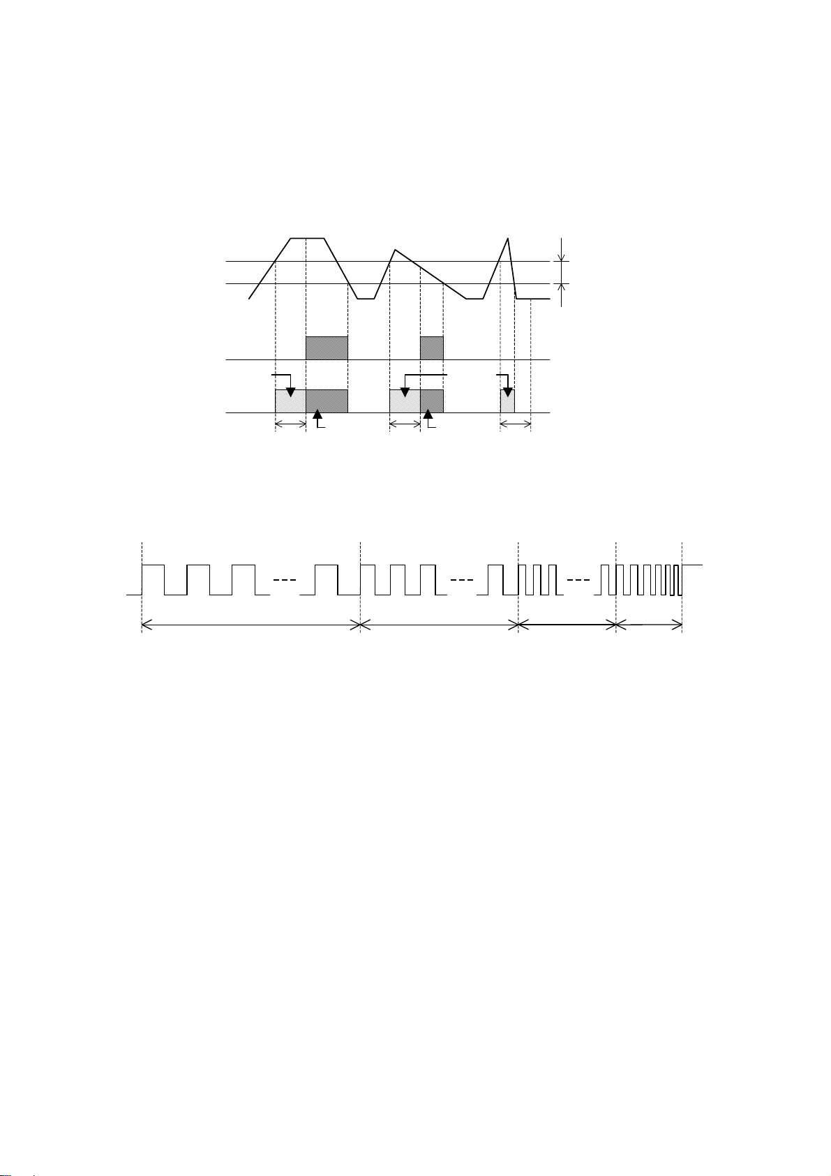
Operating time accuracy ±0.25 seconds of contact delay time set value
(However, in case of set value = 0 second. 0.5±0.25 seconds)
Reset time Less than 0.5 seconds
Starting delay time
accuracy ±0.25 seconds of starting delay time set value
Influence of temperature 0.2% (For input span) /23±10℃
Influence of auxiliary
supply voltage variation 0.1% (For input span) /Within variation range
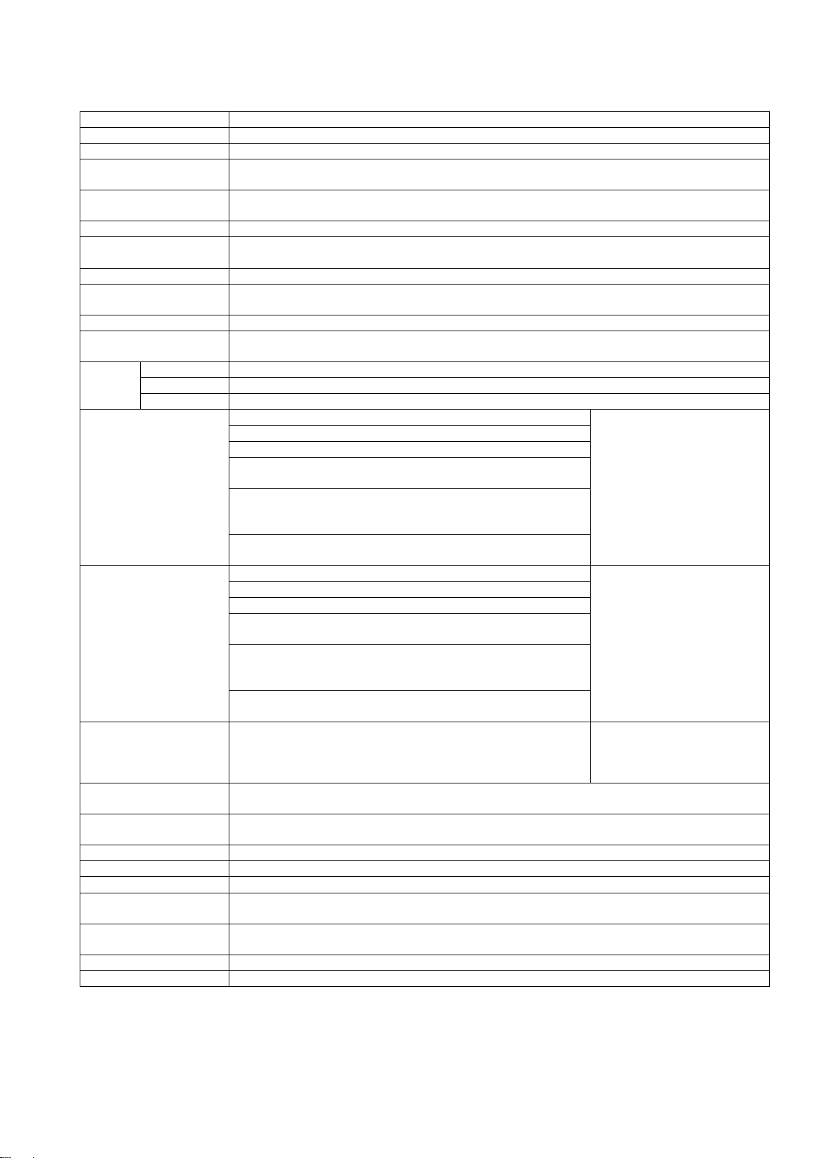
Operation period About 0.1 second
Response time About 0.5 second
(In case 90 to 110% of step variation of operation value setting is given, in CD=0 second)
Overload
capacity
Voltage input 2 times 10 seconds and 1.5 times continuation of rated voltage.
Current input 10 times 5 seconds and 1.5 times continuation of rated current.
Aux. supply 1.5 times 10 seconds of rated voltage. And upper limit of the variation range is continued.
Insulation resistance
Between electric circuit and case.
Above 50MΩ at DC500V.
Between input, output terminals and auxiliary supply terminals.
Between input terminals and output terminals.
Between AL1 output terminals and AL2 output terminals.
(Only two alarm contact output specification)
Between AL1 output terminals and AL2 output terminals
and AL3 output terminals.
(Only three alarm contact output specification)
Between AL1・AL2 output terminals and AL3・AL4 output terminals.
(Only four alarm contact output specification)
Power frequency
withstand voltage
Between electric circuit and case.
AC2000V (50/60Hz) 1 minute.
There must not be malfunction.
Between input, output terminals and auxiliary supply terminals.
Between input terminals and output terminals.
Between AL1 output terminals and AL2 output terminals.
(Only two alarm contact output specification)
Between AL1 output terminals and AL2 output terminals
and AL3 output terminals.
(Only three alarm contact output specification)
Between AL1・AL2 output terminals and AL3・AL4 output terminals.
(Only four alarm contact output specification)
Impulse withstand
voltage Between electric circuit and case.
5kV 1.2/50
μ
s.
Positive and negative
polarity for each 3 times.
There must not be malfunction.
Vibration Vibration of vibration frequency 16.7Hz,Double amplitude 1mm. In the direction of X Y Z for
each 10 minutes. There must not be malfunction.
Shock Error:98m/s
2
, X, Y, Z direction for each 3 times.
Duration:294m/s
2
, X, Y, Z direction for each 3 times.
Power failure guarantee Each set value is data-saved by non-volatilized memory.
Material of case Case:Flame resisting ABS resin , Name plate:Polyester film , Socket:Glass filled PBT resin
Appearance color Case, Socket:Munsell N1.5 (Black) , Name-plate:Gray
Operating temperature
and humidity limits -10 to +55℃ , 5 to 90%RH (Non condensing)
Storage temperature
limits -25 to +70℃
Mass Approx. 350g
Accessories Socket,Unit symbol sheet,Instruction manual
Note(4) Input is DC60mV to less than 1V, DC±60mV to less than ±1V. ±0.2% (% for input span)
Note(5) Input is DC60mV to less than 1V, DC±60mV to less than ±1V. ±0.2% (% for input span) ±1digit.
note(6) In more than 10000 (5 digits except decimal point), a measurement display span constitutes ±0.1% (%
for input span)±2digit. And, if input is less than 1V and measurement display span is 10000 or more.
±0.2% (% for input span) ±2digit.

SDLC-207-104
10
● About transition of a contact
In DC load switching, transition of a contact may start and a contact may
not return by uneven connection.
A contact evaporates locally with arc heat, what carried out contact
evaporation to + polarity → - polarity carries out the adhesion deposition
of this, and a single-sided convex opposite side serves as a concave.
〈Measure〉Be sure to use each relay within a rated load.
3. Installation
3.1 Outline dimension drawing (Unit mm)
For 3 contact
Monitor lamp
For 2 contact
Monitor lamp
For 4 contact
Monitor lamp
Note(7) Please use UR-1 combining the alarm setter of voltage input.
If an open measure is required in case the alarm setter of a current input is exchanged in the state
of a hot line, please use UR-1 for a socket, connecting (converting into a voltage signal).
(UR-1, resistance designation,Option)
Resistance in input signal
Input
Resistance
DC0‐1mA DC0‐10mA DC0‐16mA DC0‐20mA DC2‐10mA DC4‐20mA DC10‐50mA
10Ω - DC0‐100mV DC0‐160mV DC0‐200mV DC20‐100mV DC40‐200mV DC100‐500mV
50Ω - - - DC0‐1V DC100‐500mV DC0.2‐1V DC0.5‐2.5V
62.5Ω - - DC0‐1V - - DC0.25‐1.25V -
100Ω DC0‐100mV DC0‐1V - - - DC0.4‐ 2V DC1‐5V
250Ω - - - DC0‐5V - DC1‐5V -
500Ω - DC0‐5V - DC0‐10V DC1‐5V - -
1kΩ DC0‐1V DC0‐10V - - - - -
3.2 Mounting dimension drawing (Unit mm)
Contact
Contact
The tightening torque of mounting
screw.
M4:1.08 to 1.47N・m (11 to 15kg・cm)
Please prepare the installation
interval more than the above in
consideration of radiation by the
natural convection of air.
If the duct for wiring is used,
please detach 20mm or more from the
upper surface and the undersurface
of a body.
If it mount in a DIN rail, please use
the DIN rail of 35mm width.

SDLC-207-104
11
3.3 Connection
■ Connection diagram
Please refer to the connection diagram for wiring.
The polarity of ( ) is the case where a control power supply is DC.
The tightening torque of mounting screw. M3.5:0.7 to 0.9N・m (7.1 to 9.2kg・cm)
< Caution >
Please do not make a wiring change of the input and auxiliary supply in an energization.
Please be sure to work after intercepting a source.
Please do not touch a terminal etc. at the case of cleaning and check.
A fire-damaged accident may be caused by the wiring difference in auxiliary supply or input.
Please be careful of wiring enough. And, check in the place which has combustibles, an inflammable medicine,
inflammable gas, etc. in environment is also dangerous.
When inductive loads (electromagnetic relay, etc.) are connected to output contact, It recommends attaching
diode (or surge killer) etc. near the load.
3.4 Cautions on mounting
State of mounting
There is no limit of mounting position. Mounting instruction can select 35mm width DIN rail mounting and
screw mounting. In screw mounting, please mount with M4 screw. (However, the screw is not attached.
And, please give the mounting torque of a screw as 1.08 to 1.47N・m (11 to 15kg・cm)).
Should establish of side-by-side mutual mount space 5mm over up. A vertical interval should prepare
space 90mm or more in consideration of radiation and a wiring space.
State of wiring
Please separate wiring of input and output and perform consideration to noise. And, please separate from
a line with the power line used as the source of a noise and steep voltage, and current as much as possible.
Please use shielding wire for the bottom of the remarkable environment of a noise.
Conditions of environment
(1) The range of the temperature and humidity of environment.
Please give temperature and humidity as a next range from operation of each device.
Temperature:-10 to +55℃,Humidity:5 to 90%RH (Non condensing)
(2) Environment atmosphere
The case has sealing construction. However, be careful of employment under environment with much dust.
Please consult on the occasion of the employment under corrosive gas environment, such as hydrogen sulfide
gas (H2S) and chlorine gas (Cl).

SDLC-207-104
12
3.5 LCD viewing angle
Mount the LCD to obtain an optimum
angle, since the contrast changes
according to the monitoring
angle.
4. Operation method
4.1 The name and function of each part
LCD display
Measured value (real scale) and each set value is indicated.
The back-light is turn on a light at the case of key switch operation.
The back-light puts out the light after 30 seconds of key switch
operation finishing. The back-light is turn off the lights after
30 seconds of ending key switch operation.
Key switch (8)
The mode to display is changed.
Set value check. The update of data is performed.
The shift of set value is performed.
Monitor lamp
AL1 to AL4:The turn on a light by relay excitation.
If a pre-alarm is ON (No.28 PREAL:ON) at setting, a monitor
lamp is blinking from operation value detection to a contact
delay time closure.
Note (8) Please operate at a moderate force without applying excessive force to the key switch.
If you press the key switch in excessive force, there is a possibility that affect the display
becomes a stress on the front plate.
Side view Top view
Front
30 ゜
15 ゜
Top
Back
Under
Front
Back
SDLC-105A
Socket
45 ゜ 45 ゜
Movement of setting item is performed and change of set
value is made.

SDLC-207-104
13
4.2 Each display mode and operation
Shift in each mode
A display mode shifts to each mode by those with four type, and the following switch operations.
UP
Power supply
①
Measurement mode
② Set value
display mode
③ Set value change mode
If key switch operation is not performed for
30 seconds in a set value display mode, it
shifts to measurement mode.
MODE
Push key
UP
MODE
It pushes for 3 seconds simultaneously.
④ Setting error
display
ERROR
Y
UP
MODE
It pushes for 3 seconds
simultaneously.
ENT Key
Push
N
MODE
Push key
MODE
It pushes for 3 seconds
simultaneously.
① Measurement mode
Measurement value, maximum value, and minimum value are displayed.
② Set value display mode
A setting item is displayed in order and the check of set value can be performed.
Change of set value cannot be performed.
③ Set value change mode
A setting item is displayed in order and change of set value can be performed.
Please perform the check of set value with a set value display mode.
④ Setting error display
An error code is displayed after setting change in set value change mode at the case of combination
error occurrence.
№ Contents of error Measures
ERROR 0 Scaling combination error In order that it may become MAX>MIN, it sets up again.
ERROR 1 COMP1 setting range outside error
In order that the measurement display range may become
-25 to +125%, it sets up again.
ERROR 2 COMP2 setting range outside error
ERROR 3 COMP3 setting range outside error
ERROR 4 COMP4 setting range outside error
4.3 Measurement mode
It becomes measurement mode in after the power supply. Whenever it pushes the UP key, a display changes.
An measurement value display, maximum value display, and minimum value display can be checked.
UP
UP
UP
UP
ENT
ENT
UP
Measurement value display
Reset by push 3
seconds of ENT key
Reset by push 3
seconds of ENT key
Reset of minimum
value display
Measurement value
Unit
50.0
%
Maximum value display
+PEAK
100.0
Reset of maximum
value display
-PEAK
50.0
Minimum value display
-PEAK
20.0
+PEAK
5 0 . 0
● Explanation of a key switch
Mode (Measurement set value display) change
Reset of maximum value and minimum value.
Display change
Not use
< Notes of maximum value and minimum value >
After set value change, please reset a maximum value
display and a minimum value display.

SDLC-207-104
14
4.4 Set value display mode
A setting item is displayed in order and the set value check of all items can be performed.
Once it pushes the MODE key, it will change to a set value display mode.
An common item (AL1 to AL4) is changed by the UP key. Each setting item is displayed as the SHIFT key.
5 0 . 0
%
UP UP
UP UP UP
UP
UP
SHIFT SHIFT SHIFT SHIFT SHIFT
COMP1
080.0
SHIFT SHIFT SHIFT SHIFT SHIFT
UP UP
UP UP UP
UP UP
UP UP UP
SHIFT SHIFT SHIFT SHIFT SHIFT
UP UPUP UP UP
UP UP
UP UP UP
UP
SHIFT
Measurement value display
UNIT
%
MIN
000.0
MAX
100.0
CBIAS
00.00
CSPAN
00.00
S.D.
000s
AVE
1
MODE
SHIFT
C.D.1
000s
ALMD1
High
D.B.1
03.0%
EXMD1
ON
ALMD2
High
COMP2
070.0
D.B.2
03.0%
EXMD2
ON
C.D.2
000s
ALMD3
Low
COMP3
030.0
D.B.3
03.0%
EXMD3
ON
C.D.3
000s
ALMD4
Low
COMP4
020.0
D.B.4
03.0%
EXMD4
ON
C.D.4
000s
AL1
setting
item
AL2
setting
item
AL3
setting
item
AL4
setting
item
PREAL
OFF
SHIFT
Common
setting
item
2 contact
specification
4 contact
specification
3 contact
specification
● Explanation of key switch
Mode (Measurement set value display) change.
Not use.
Common item (AL1 to AL4) is changed.
Each setting item is changed.

SDLC-207-104
15
4.5 Set value change mode
Change of each set value is possible. If the MODE+UP key is pushed 3 seconds or more simultaneously, it
will change to set value change mode.
By the same operation as a set value display mode, a setting item is shifted and it displays.
The ENT key is pushed by the item to make a setting change, and setting is changed.
Measurement value display
Blinking
It pushes for 3 seconds simultaneously.
5 0 . 0
※
UP
COMP1
080.0
UP UP
UP UP UP
UP UP
SHIFT SHIFT SHIFT SHIFT SHIFT SHIFT SHIFT
SHIFT SHIFT SHIFT SHIFT SHIFT
UP UP
UP UP UP
UP
UP UP UP
SHIFT SHIFT SHIFT SHIFT SHIFT
UP UP
UP UP UP
UP UP
UP UP UP
2 contact
specification
3 contact
specification
4 contact specification
UP
SHIFT
MODE
C.D.1
000s
UNIT
※
MIN
000.0
MAX
100.0
CBIAS
00.00
CSPAN
00.00
S.D.
000s
AVE
1
ALMD1
High
D.B.1
03.0%
EXMD1
ON
ALMD2
High
COMP2
070.0
D.B.2
03.0%
EXMD2
ON
C.D.2
000s
ALMD3
Low
COMP3
030.0
D.B.3
03.0%
EXMD3
ON
C.D.3
000s
ALMD4
Low
COMP4
020.0
D.B.4
03.0%
EXMD4
ON
C.D.4
000s
UP
PREAL
OFF
It is made to shift to setting item to change by the
same operation method as set value display mode.
UNIT
※
ENT
ENT
The unit will be displayed if it goes into set value change mode.
Please change each set value after pressing the ENT key twice from this status.
UNIT
※
※ The unit display setting
at now is displayed.
● Operation in set value change mode
In set value change mode, a setting item or set value is blinking.
In set value change mode, the back light is always turn on a light.
After a set value change mode is ended, it restarts.
● Explanation of key switch
It is not used if independent.
MODE+UP key is pushed 3 seconds or more simultaneously. Mode (Measurement set value change) change.
Set value decision(Update of data)
Determination of setting item(Blinking is upper section lower section)
Setting item movement and change of set value.
MODE+UP key is pushed 3 seconds or more simultaneously. Mode (Measurement set value change) change.
Movement of the setting item of AL1 to AL4, and the shift of set value.

SDLC-207-104
16
● Notes after a setting change end
After setting change is completed, please check that set value has been changed with a set value display mode.
After confirming the changed set value when being different from the established set value, please establish
it once again.
● If a unit display (UNIT) is set up. (9)
● If a minimum value scaling (MIN) is set up.
Note(9) If you do not have the unit you wish to use, please use a combination of "no unit" setting and
seal (accessory).
Note(10) After set value changed, displays the change set value.
Note(11) The number of the top digit becomes "-"(minus) after 0 to 9.
Note(12) The number of digits other than the top digit becomes " ."(decimal point) after 0 to 9.
However, if decimal point is in other digits, decimal point does not display.
(10)
UNIT
%
(Middle omission)
UNIT
%
UNIT
m
UNIT
m
UNIT
kW
UNIT
kW
ENT
ENT
ENT
UP
UP
UP
After deciding set value change, a setting
item symbol is blinking.
(UNIT is blinking.)
UNIT
UP
UP With no unit
UNIT
%
ENT
(10)
(Middle omission)
MIN
000.0
MIN
100.0
MIN
010.0
MIN
-00.0
MIN
090.0
MIN
000.0
MIN
000.0
(Middle
omission)
MIN
010.0
(Middle omission)
(11) (12)
MIN
000.0
SHIFT
ENT
UP
SHIFT
ENT
UP
UP
UP
UP
UP
After deciding set value change, a setting item
symbol is blinking.
(Here, MIN is blinking.)

SDLC-207-104
17
5. Block-diagram and principle of operation
5.1 Block-diagram
(+)
INPUT
(-)
Filter
protection
circuit
SWITCH
AUX.
SUPPLY
5
6
Amplifier A/D
converter
Non-volatile
memory
E
2
PROM
CPU
MODE
ENT
UP
SHIFT
(+)
(-)
Power supply
circuit
7
8
LCD
driver
100.0
%
AL1 AL2 AL3 AL4
LCD display
LED display
Relay output circuit
RY
RY
RY
RY
2
3
1
AL1
AL2
COM
10
11
9
AL3
AL4
COM
* In case of 4 contact
(1a contact) output
5.2 Principle of operation
(1) The inputted voltage or current passes along a filter protection circuit, and becomes the DC voltage below
constant voltage. This voltage goes into an amplifier.
(2) The input is converted into the suitable voltage range in an amplifier. This voltage constitutes an input
of an A/D converter.
(3) The data converted into digital one by the A/D converter are sent to CPU. A/D converter has 16-bit resolution
and performs operation and conversion with 1MHz clock. Based on the scaling range that had this data set
up, it calculates within CPU. And the measurement value scaling by the LCD is displayed.
(4) The operation value and measurement value, which was set up beforehand, are compared, and the relay and LED
are operated.
(5) The front pushbutton switch makes each setting change.
(6) The value set up by the switch is saved at non-volatile memory (E2PROM). ROM has the capacity of 128×16 bits.

SDLC-207-104
18
6. Inspection
6.1 Receiving inspection
In case you inspect at the time of receiving, please perform after reference the following.
(1) Structure
Inspection of an outline dimension, mounting dimension, and appearance.:Please perform with reference to
dimensional outline drawing.
(2) Performance
Please do a reserve energization (warm-up) for 15 minutes after a power supply apply. After that, please
conduct performance inspection. Performance inspection is performed with reference to 7.2 "calibration
method".
6.2 Periodic inspection
Please perform the following item if needed.
(1) Please check each set value.
(2) The accuracy test of indicated value.
An input tests indicated value as two to five points.
(3) Alarm output operation and setting accuracy.
The check with normal ON/OFF operation. The accuracy of operation value and reset value (dead band) is tested.
7. Check, calibration and maintenance
7.1 Check
It is not necessary to check especially every day. Please be periodically careful of the next item.
(1) It is checked whether a body and socket combination are normal (is a lock a totality?).
(2) It checks for the slack of wiring, and the slack of a captive screw.
(3) It will remove, if dust has adhered to the case.
7.2 Calibration
Calibration is performed in the calibration circuit of the right
figure.
(1) Please do a reserve energization (warm-up) for 15 minutes after
a power supply apply.
(2) When the input equivalent to the minimum display is applied,
in order that it may become the minimum display, set value
CBIAS is set up.
Next, when the input equivalent to the maximum display is applied,
in order that it may become the maximum display, it sets up
by set value CSPAN.
Calibration is finishing, if the above is checked again and
the display is correct. In addition, please refer to the
4.5 section "set value change mode" about setting of set
value CBIAS and CSPAN.
(3) Please perform the check of an operation value, a reset
value, and a dead band.
Note(13) It is the polarity of ( ) at the DC power supply case.
AUX.SUPPLY
High accuracy DC
voltage (current)
generator
8 7 6 5
4
3
9
10 11 1 2
(-) - +
(+)
(13)
SOCKET
INPUT
The set tester for alarm output check
(Contact ON/OFF check) OUTPU
T

SDLC-207-104
19
7.3 Trouble shooting
Abnormal phenomenon Cause of estimated Method of settlement
It does not output.
The power supply input is not applied Please power supply-input-check and apply.
An alarm setter trouble Repair of alarm setter
The input is not connected Please confirm connection of input.
Abnormal of input Please confirm measurement value.
The error of setting Please confirm set value.
The output is not connected. Please confirm connection of output.
Power-supply voltage is low. Please confirm power-supply voltage.
Display is abnormal.
(Large error)
Power-supply voltage is not regulation
range.
Please check power-supply voltage and give as
regulation range.
The input is abnormal. Please give a measurement value as a check and a
normal input.
The error of set value Please confirm set value.
An alarm setter trouble Repair of alarm setter
Display error
(Small error) Secular change of input measurement Display is proofread again.
(Reference of instruction manual 7.2 section)
Set value cannot be
changed.
The error of the setting method Please check setting method.
(Reference of instruction manual 4.5 section.)
An alarm setter trouble Repair of alarm setter
An error is
displayed.
ROM SUM value error Repair of alarm setter
At the time of an EEP error, if the ENT key is
pressed, it will become set value change mode.
Please confirm set value.
RAM READ/WRITE error
EEP Saving value error
A/D A/D conversion error
7.4 Countermeasures against troubles
As our principle, we recall product in question and repair it. If judged as product failure, have a contact with
us or sales agent for repairing work (Also have a contact with us or sales agent for specification change).
Product failure which we are not responsible for (When responsibility in manufacturing process is not recognized,
when product is disassembled/remodeled, in case of false operation by customer, etc.) is beyond our warranty.
Table of contents
Other Daiichi Electronics Measuring Instrument manuals