Daiichi Electronics SFLC-110L User manual

SFLC-212-173
INSTRUCTION MANUAL
POWER LINE MULTI-METER
SFLC-110L
1φ2W / 1φ3W / 3φ3W
ANALOG OUTPUT
HARDWARE MODEL F

SFLC-212-173
1
Thank you for your purchase of our product.
Read this instruction manual carefully before installation, wiring, and using this product.
Safety concerns
Environment and conditions of usage
Please be sure to use this product in a place that meets the following conditions.
In places that do not meet this condition, it may cause malfunction or failure and product life decline.
Within the range of ambient temperature -10 to +55 ℃, humidity 85% RH or more.
Place free of dust, corrosive gas, salt and oily smoke. (Corrosive gas:SO2
/
H2S, etc.)
Location that is not affected by vibration and shock.
Location that is not affected by external noise.
Altitude 2000m or less.
If this unit directly measures an inverter output of cycle control, SCR phase angle control or PWM control,
an error may increase due to its operation principle.
The precautions at the case of using by outdoor panel.
These products are not a dustproof construction, waterproof construction, and splash proof construction.
Please avoid the place with much dust. Moreover, please install in the place which requires neither rain
nor waterdrop.
Please do not install in the place where sunlight hits directly.
Discoloration and degradation of a name plate, and cover is deformed by the surface temperature rise.
Installation and wiring
Installation and wiring, refer to the instruction manual, please be conducted by engineers.
And, please observe the following notes.
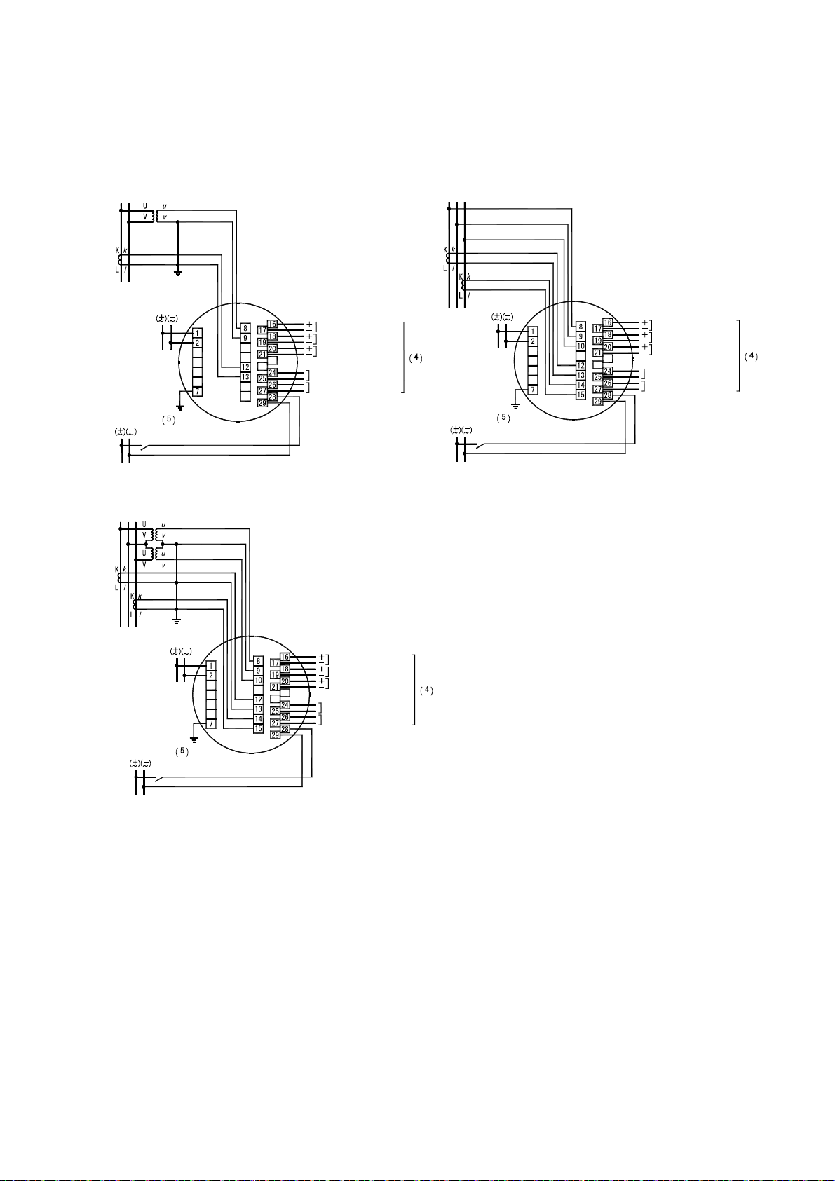
Please wire after the connection diagram is checked.
Please forbid a hot line work.
Please use the size of the electric wire that is suitable for conducting current.
Please securely tighten the terminal screws. Please make sure that forgotten tightening
of the terminal screw is not.
Preparation before use
At the case of connect this product to the main power supply directly, please put the suitable fuse to the outside.
This product must be set before use. Reading this instruction manual, please set correctly.
About dew condensation
If the temperature and humidity of an installation change rapidly when a product is a non-energization, the
waterdrop by dew condensation may adhere to a display inner side. (The display filter and the LCD surface
stick and the pattern of the shape of a circle or an ellipse occur.)
This phenomenon is not trouble. It will disappear, if a control power supply is applied and about 2 hour passes.
Maintenance
Inspection of energized is dangerous.
There is no parts to be replaced on a regular inspection.
Please wipe off lightly with the dry soft cloth. When it wipes with the damp cloth or the dry cloth strongly,
a surface is damaged. And, the character of a name plate may disappear.
Please do not use the organic solvent, chemicals, cleaners, etc., such as an alcohol, for cleaning.
The liquid crystal display (LCD) may light during cleaning on the LCD face. However, this phenomenon is caused
by the static electricity that may be produced in the filter, and it does not show any trouble.
Leave the unit as it is for a while, and the display goes out due to natural discharge.
Do not press the LCD face strongly, otherwise it may be broken. When the filter has been pressed, it may touch
the LCD face to stain the LCD face. However, this phenomenon does not show any trouble, but it is caused by
a change of the ambient environment or the like. The LCD face may be restored to its original condition after
a while during the use as it is.

SFLC-212-173
2
Storage
Please be storage in a place that meets the following conditions.
Within the range of ambient temperature -20 to +70 ℃.
The average temperature (day) 40 ℃ or less.
Place free of dust, corrosive gas, salt and oily smoke.
Location that is not affected by vibration and shock.
The aluminum electrolytic capacitor is used for a product. Please do the energization of the power
supply within one year after shipment.
Countermeasures against troubles
If the product has failed, we can repair pick up the product.
Proper disposal
Please dispose of this product as industrial waste (noncombustible).
Mercury parts and a nickel-cadmium battery are not used for this product.
Warranty period
The warranty period of this product is for one year after supplying the appointed place.
Operation
Be careful with the following cautions during use.
Use the input within the rated range. Be careful since negligence of this caution may cause troubles of
the unit.
There is a function to hold the maximum value and the minimum value with a measurement factor in this product.
A blackout is guaranteed and this value isn't also cleared by a power supply reset. However, the minimum value
may be updated in case input is not applied to a power up. For this reason, in order to make the past minimum
value hold by powering on, please apply input within 1 second after switching on a power supply.
The maximum value, a minimum value measurement factor
Measurement factor Maximum value
measurement
Minimum value
measurement
Voltage,Current ,Demand current ,Active power ,Demand power ,
Reactive power ,Power factor ,Frequency ○ ○
Be careful not to touch any terminal when power is applied to the unit.
Don’t disassemble or modify this unit without any previous permission of our company,
otherwise the warranty does not apply to the unit any more. Also, modifications may cause
troubles, a fire, or other accidents. For specifications change, etc., please contact us.
Please forbid a hot line work.
Setting
This unit requires setting and confirmation of the measuring range, etc. before use.
Wrong setting, if any, causes malfunction of the unit. If setting should be wrong, neither measurement nor output
becomes correct. Carefully read the instruction manual before setting the unit.
Default setting
The default settings are as specified below at the delivery time. Set them according to the working conditions.
The input circuit of this product is the common use of 3-phase 3-wire (3φ3W), single-phase 2-wire (1φ2W), and
single-phase 3-wire (1φ3W). In case an input circuit is designated at the case of an order, it is shipped by the
default value of the designated input circuit. And, in case it does not do designation of the input circuit (with
no designation), it is shipped by the default value of 3-phase 3-wire (110V).
The unit will be delivered with your specified setting values, if so specified.

SFLC-212-173
3
№ Setting item
3-phase 3-wire Single-phase
3-wire
(U-N-W)
Single-phase
110V input 220V input 110V input 220V input
1 Display
combination
Pattern Pattern 1 Pattern 1 Pattern 1
Main monitor A(V) A(U) A
Sub monitor (Left) V(UV) V(UN) V
Sub monitor (Center) W W W
Sub monitor (Right) Wh Wh Wh
Bar graph A(V) A(U) A
2 Alarm output
(1)
Factor DA DA DA
Reset form AUTO AUTO AUTO
Contact delay time 0 second 0 second 0 second
3 Demand
detection
Demand
current
Upper limit <H> 80.0A 400.0A 40.00A
Interval 0 second 0 second 0 second
Demand
power
Upper limit <H> OFF OFF OFF
Interval 0 second 0 second 0 second
Operation form
Operating system
according with bimetallic
type.
Operating system
according with
bimetallic type.
Operating system
according with bimetallic
type.
4
Instant
measurement
detection
Voltage upper limit OFF OFF OFF
Voltage lower limit OFF OFF OFF
5 Backlight Action AUTO AUTO AUTO
Brightness (4) 3(Middle) 3(Middle) 3(Middle)
6 Measurement
range
Voltage range 6600V 220.0V 110.0V 3300V 220.0V
Digit number of voltage range 4 digits 4 digits 4 digits 4 digits 4 digits
Current range 100.0A 500.0A 50.00A
Current display intrinsic
sensitivity 100.0A 500.0A 50.00A
Digit number of current range 4 digits 4 digits 4 digits
Active power polarity One-way deflection One-way
deflection One-way deflection
Active power range 1200kW
( /1kW)
40.00kW
( /2kW) 100.0kW ( /1kW) 150.0kW
( /500W)
10.00kW
( /1kW)
Digit number of active power
range 4 digits 4 digits 4 digits 4 digits 4 digits
Reactive power range
LEAD 600.0
to 0.0 to
LAG
600.0kvar
( /500var)
LEAD 20.00
to 0.00 to
LAG
20.00kvar
( /1kvar)
LEAD 50.00 to 0.00
to LAG 50.00kvar
( /500var)
LEAD 75.00
to 0.00 to
LAG
75.00kvar
( /250var)
LEAD 5000
to 0 to
LAG 5000var
( /500var)
Digit number of reactive
power range 4 digits 4 digits 4 digits 4 digits 4 digits
Power-factor range LEAD0.500 to 1.000 to
LAG0.500
LEAD0.500 to
1.000 to LAG0.500
LEAD0.500 to 1.000
to LAG0.500
Frequency range 45.0 to 65.0Hz 45.0 to 65.0Hz 45.0 to 65.0Hz
Digit number of frequency range
3 digits 3 digits 3 digits
7
Analog
output
(1)
Output factor 1 A(V) A(U) A
Output factor 2 V(UV) V(UN) V
Output factor 3 W W W
Output
intrinsic
sensitivity
Current 100.0% 100.0% 100.0%
Active power 100.0% 100.0% 100.0%
Reactive power 50.0% 50.0% 50.0%
Low input cut OFF OFF OFF
8 Pulse output
(1)
Factor Wh Wh Wh
Pulse unit 10kWh/pulse 0.1kWh/pulse 1kWh/pulse 1kWh/pulse 0.1kWh/pulse
9 External operation input (1) Alarm reset Alarm reset Alarm reset

SFLC-212-173
4
№ Setting item
3-phase 3-wire Single-phase
3-wire
(U-N-W)
Single-phase
110V input 220V input 110V input 220V input
10
Measurement
display
ON/OFF
Voltage ON ON ON
Current ON ON ON
Demand current ON ON ON
Active power ON ON ON
Demand power ON ON ON
Reactive power ON ON ON
Power-factor ON ON ON
Frequency ON ON ON
Watt-hour of power receiving ON ON ON
Watt-hour of power
transmission ON ON ON
var-hour of power receiving ON ON ON
var-hour of power
transmission ON ON ON
11 Input
circuit
Phase line change (6) 3φ3W 1φ3W (U-N-W) 1φ2W
Input voltage (7) 110V 220V 150V 110V 220V
12 Measurement Tidal current measurement General measurement General
measurement General measurement
13
Analog
output
adjustment
(5)
Output 1 Bias adjustment 0.0% 0.0% 0.0%
Span adjustment 100.0% 100.0% 100.0%
Output 2 Bias adjustment 0.0% 0.0% 0.0%
Span adjustment 100.0% 100.0% 100.0%
Output 3 Bias adjustment 0.0% 0.0% 0.0%
Span adjustment 100.0% 100.0% 100.0%
Note(1) A setting item is not displayed in case there is no corresponding option.
Note(2) When the input circuit phase line switching setting is changed, the setting values of setting 1 and
setting 2 (No. 1 to 10 in the table) return to the default setting values of the switched phase line.
However, the value of setting 3 (No. 11 to 13 in the table) does not return to the initial setting.
Note(3) When phase line change setting of an input circuit is set as 3φ3W (or 1φ2W) and the input voltage
setting is changed, the voltage range returns to the default value of the phase line.
(For example:In case of 3φ3W, 6600V at the case of 110V setting, 220.0V at the case of 220V setting.)

SFLC-212-173
5
Content
Safety concerns ・・・・・・・・・・・・・・・・・・・・・・・・・・・・・・・・・・・・・・・・・・・・・・・・・・・・・・・・・・・・・・ 1
1. Product outline ・・・・・・・・・・・・・・・・・・・・・・・・・・・・・・・・・・・・・・・・・・・・・・・・・・・・・・・・・・・ 6
1.1 Usage of product ・・・・・・・・・・・・・・・・・・・・・・・・・・・・・・・・・・・・・・・・・・・・・・・・・・・・・・・ 6
1.2 Features of product ・・・・・・・・・・・・・・・・・・・・・・・・・・・・・・・・・・・・・・・・・・・・・・・・・・・・ 6
1.3 Composition of type ・・・・・・・・・・・・・・・・・・・・・・・・・・・・・・・・・・・・・・・・・・・・・・・・・・・・ 6
2. The name and function of each part ・・・・・・・・・・・・・・・・・・・・・・・・・・・・・・・・・・・・・・・・ 7
3. Preparation
3.1 Installation ・・・・・・・・・・・・・・・・・・・・・・・・・・・・・・・・・・・・・・・・・・・・・・・・・・・・・・・・・・・ 8
3.2 Connections ・・・・・・・・・・・・・・・・・・・・・・・・・・・・・・・・・・・・・・・・・・・・・・・・・・・・・・・・・・・・ 9
4. Operation ・・・・・・・・・・・・・・・・・・・・・・・・・・・・・・・・・・・・・・・・・・・・・・・・・・・・・・・・・・・・・・・・・ 10
4.1 The screen change and function by switch operation ・・・・・・・・・・・・・・・・・・・・・ 11
4.2 The kind of display ・・・・・・・・・・・・・・・・・・・・・・・・・・・・・・・・・・・・・・・・・・・・・・・・・・・・ 12
4.2.1 Measurement display ・・・・・・・・・・・・・・・・・・・・・・・・・・・・・・・・・・・・・・・・・・・・・・・・・ 12
4.2.2 Alarm detection display ・・・・・・・・・・・・・・・・・・・・・・・・・・・・・・・・・・・・・・・・・・・・・ 13
4.2.3 Setting display ・・・・・・・・・・・・・・・・・・・・・・・・・・・・・・・・・・・・・・・・・・・・・・・・・・・・・ 15
4.3 Operation ・・・・・・・・・・・・・・・・・・・・・・・・・・・・・・・・・・・・・・・・・・・・・・・・・・・・・・・・・・・・・・ 16
4.3.1 The main monitor display-element change ・・・・・・・・・・・・・・・・・・・・・・・・・・・・・ 16
4.3.2 Phase (line) display change ・・・・・・・・・・・・・・・・・・・・・・・・・・・・・・・・・・・・・・・・・ 16
4.3.3 Enlarged display of integral power consumption ・・・・・・・・・・・・・・・・・・・・・・ 17
4.3.4 Setting value check ・・・・・・・・・・・・・・・・・・・・・・・・・・・・・・・・・・・・・・・・・・・・・・・・・ 17
4.3.5 Setting mode ・・・・・・・・・・・・・・・・・・・・・・・・・・・・・・・・・・・・・・・・・・・・・・・・・・・・・・・・ 18
4.3.6 Reset ・・・・・・・・・・・・・・・・・・・・・・・・・・・・・・・・・・・・・・・・・・・・・・・・・・・・・・・・・・・・・・・ 19
5. Setting
5.1 Function table ・・・・・・・・・・・・・・・・・・・・・・・・・・・・・・・・・・・・・・・・・・・・・・・・・・・・・・・・・ 22
5.2 Setting table ・・・・・・・・・・・・・・・・・・・・・・・・・・・・・・・・・・・・・・・・・・・・・・・・・・・・・・・・・・ 26
5.3 Setting in detail explanation ・・・・・・・・・・・・・・・・・・・・・・・・・・・・・・・・・・・・・・・・・・ 33
5.3.1 Setting mode 1 ・・・・・・・・・・・・・・・・・・・・・・・・・・・・・・・・・・・・・・・・・・・・・・・・・・・・・・ 33
5.3.2 Setting mode 2 ・・・・・・・・・・・・・・・・・・・・・・・・・・・・・・・・・・・・・・・・・・・・・・・・・・・・・・ 41
5.3.3 Setting mode 3 ・・・・・・・・・・・・・・・・・・・・・・・・・・・・・・・・・・・・・・・・・・・・・・・・・・・・・・ 49
6. Specification
6.1 Specification and intrinsic error ・・・・・・・・・・・・・・・・・・・・・・・・・・・・・・・・・・・・・・ 53
6.2 Performance ・・・・・・・・・・・・・・・・・・・・・・・・・・・・・・・・・・・・・・・・・・・・・・・・・・・・・・・・・・・・ 55
6.3 Option ・・・・・・・・・・・・・・・・・・・・・・・・・・・・・・・・・・・・・・・・・・・・・・・・・・・・・・・・・・・・・・・・・ 57
7. Maintenance and check
7.1 Trouble shooting ・・・・・・・・・・・・・・・・・・・・・・・・・・・・・・・・・・・・・・・・・・・・・・・・・・・・・・・ 58
7.2 Test ・・・・・・・・・・・・・・・・・・・・・・・・・・・・・・・・・・・・・・・・・・・・・・・・・・・・・・・・・・・・・・・・・・・ 59
Appendix table 1 to 3

SFLC-212-173
6
1. Product outline
1.1 Usage of product
This single unit can measure and monitor voltage ×3, current ×3, demand-current ×3, active-power, demand
active power, reactive-power, power-factor, frequency, watt-hour, var-hour.
The measurement monitor of an initial power receiving circuit, an energy conservation power monitor, a demand
current measurement monitor, etc. are adapted for various usages from a low tension circuit to a high tension
circuit. The intensive monitor doubled with the system by option (analog output, alarm output, pulse output,
external operation input) addendum is possible.
1.2 Features of product
High-performance products which collected the function of the power line multi-meter (QLC-110L, DLC-110L)
of our company.
This product is 3-phase 3-wire, single-phase 2-wire, single-phase 3-wire common type.
Product inventory can be standardized.
Bar graph 1 measurement and digital 4 measurement are displayed simultaneously.
Analog output 3 circuit and a pulse output and a contact-output can be taken out. (Option)
And, An output factor can be selected by setting.
External operation inputs are possible of reset. (Option) Choice of an alarm output, the maximum/minimum value,
and an alarm output, and the maximum/minimum value is possible at setting.
Power supply is AC85 to 264V,DC80 to 143V (for both AC and DC uses).
The mounting method of this unit is compatible with the mounting method of conventional 110 square
mechanical meter. This unit is mounted at 2 diagonal points.
Integrated value of Wh and varh can indicate expansion to 3rd digit below the decimal point.
A tidal current measurement (output 2 quadrant) change is possible for var and cosφ.
With backlight (white LED backlight) function.
In addition, the selection of the on / off / auto off and, you can set the brightness.
LCD can be chosen from 2 kinds, the type to see from the top and the type to see from the bottom.
(Please designate it at an order.)
1.3 Composition of type
TYPE Specification code
SFLC-110L-□□□□□-□□□
Installation position
1:For an upper installation.
2:For an lower installation.
Option
Specification
code
External operation
input
Analog output or
communication output Contact output
0-00 Nothing Nothing Nothing
1-11 One circuit DC4 to 20mA×3 circuits Pulse + Alarm
1-M1 One circuit Modbus RTU (RS-485) Pulse + Alarm
1-A1 One circuit Protocol A (RS-485) Pulse + Alarm
Auxiliary power supply
1:AC85 to 264V, DC80 to 143V for both AC and DC uses
Input range
F:Common use for AC150V, AC300V. AC5A
Input circuit
F:Common use for 1φ2W, 1φ3W, 3φ3W.
Hardware model
D:R-S-T,White backlight
E:R-Y-B,White backlight
F:U-V-W,White backlight

SFLC-212-173
7
2. The name and function of each part
If this switch is pushed 1 second or more
continuously, it will reset an alarm, the maximum
value, and the minimum value (factor which it is
displaying on the main monitor).
In setting mode, it uses it as a switch to which it
moves a setting item (move up).
Bar graph display
The measurement value of the main monitor
is indicated by the analog.
(Setting which does bar graph display
of the measurement value of sub monitor
is also possible.)
Digital display
Measurement monitor can watch
4 elements at the same time.
・Main monitor
・Sub monitor (Right)
・Sub monitor (Center)
・Sub monitor (Left)
SET
The switch from which integrated
value of the amount of electric
power is switched to normal display
(5 digits of integer) and expansion
indication (integer 2 digits + below
decimal point, 3 digits) variously.
If it is not operated for 10 minutes after a
display change, it will usually return to a
display. It is used also as a switch which
changes to setting mode. If it continues
pushing 3 seconds or more, it will change to
setting mode.
In setting mode, it is used as a switch that
determines a set point.
RESET/
SHIFT
Scale markings
It sets automatically by measurement-range
setting.
Unit display
It sets automatically by measurement-range
setting.
Upper limit (or lower limit) setting index
An upper limit (or lower limit) set point is
displayed.
Multiplying factor display
It displays on the lower right of the main
monitor at the time of watt-hour and var-hour
display.
MODE
In setting mode, it is used as a switch that changes a setting
item.
DISPLAY
It is the switch that changes a phase
(line) display of current (voltage).
If it is not operated for 10 minutes after a
display change, it returns to the original
phase (line) display. In setting mode, it is
used as a switch that terminates setting mode.
The switch to which measurement displays
element of main monitor is changed.
If it is not operated for 10 minutes after a display
change, it returns to the original measurement display
factor. In set mode, it is used as a switch that changes
a setting value.
MAX/MIN
The switch to which general measurement display (usually)
and the maximum minimum measurement display are changed.
In setting mode, it uses it as a switch to which it moves a
setting item (move down).
+ -

SFLC-212-173
8
3. Preparation
3.1 Installation
Mount the unit by the attached M5 nuts to a panel of thinner than 10mm, referring to the following external
dimensions drawing and panel cutout. Fasten these nuts with tightening torque 2.0 to 2.5N・m.
● Dimension diagram
● Caution on handling
Mount the LCD to obtain an optimum angle, since the contrast changes according to the monitoring angle.
(1) For upper case installation (2) For lower case installation
● Installation
(1) A product is put in a cut hole of a panel from a front.
A body is inserted until it exceeds retaining stopper
of the lower base.
(2) Please fix a product certainly with attached M5
flange nut for installation. Please give a
tightening torque as 2.0 to 2.5N・m.

SFLC-212-173
9
3.2 Connections
Please perform connection after referring to the following wiring diagram.
● Connection drawing (6)
(1) 1φ2W,Analog output. (2) 1φ3W, Analog output.
CT
EXT.INPUT
AUX.SUPPLY
LOAD
VT
CT
UV
ALARM OUTPUT
ANALOG OUTPUT 3
ANALOG OUTPUT 2
ANALOG OUTPUT 1
PULSE OUTPUT
EXT.INPUT
AUX.SUPPLY
LOAD
NUW
ANALOG OUTPUT 1
ANALOG OUTPUT 2
ANALOG OUTPUT 3
ALARM OUTPUT
PULSE OUTPUT
(3) 3φ3W, Analog output
EXT.INPUT
ANALOG OUTPUT 3
ALARM OUTPUT
PULSE OUTPUT
AUX.SUPPLY
LOAD
CT
WVU VT
ANALOG OUTPUT 1
ANALOG OUTPUT 2
● Caution on connection
(1) Mount the terminal cover without fail for safety after the end of connections.
(2) Separate the input wiring and output wiring from each other without fail, and take a preventive measure
against malfunction due to external noises.
(3) Connect the grounding terminal E (No. 7 terminal) to the ground without fail for enhancing the shield effect.
Keep the grounding resistance between the grounding terminal and the ground to be lower than 100Ω.
(4) Keep a distance of more than 30cm between this unit and the circuit breaker as well as between this unit
and the relay contact signal line.
(5) No protection is necessary for this unit even if the transmission line may be affected by an induced lightning
surge or the like when transmitting an analog output to the receiver. Mount an about 500V arrester or
the like between the line surge protector and the ground as well as between the transmission line and
the ground on the receiver side for the purpose of protecting the devices on the receiver side.
(6) It is recommended to mount a surge killer outside when connecting an inductive load to the pulse output
and alarm output. If no surge killer is mounted, the contact life may shorten.
Note(4) Analog output, pulse output, alarm
output, external operation input is an
option.
Note(5) By setting, it can switch an external
operation input.
Alarm reset. Maximum, minimum value reset.
Alarm and maximum, minimum value all
reset.
Note(6) In case of low-voltage circuit, secondary
side earthing of VT and CT is unnecessary.
And, VT is unnecessary in case it used 110V
or direct 220V.

SFLC-212-173
10
4. Operation
● The function of switch
Switch Function
SET
The integrated value of electric energy is changed to the usual display and an enlarged display.
If it continues pushing 3 seconds or more, it will change to setting mode.
In setting mode, it is used for the determination of a set point.
RESET/SHIFT
Various kinds of alarms are reset. The maximum value and the minimum value are reset in the maximum
minimum measurement display. In setting mode, it uses it as a switch to which it moves (move up)
a setting item.
MODE
In setting mode, it is used for the change of a setting item.
MAX/MIN
The usual measurement display and maximum value or minimum value display are changed.
In setting mode, it uses it as a switch to which it moves (move down) a setting item.
+
,
-
The measurement display element of the main monitor is changed.
In setting mode, it is used for change of a set point.
DISPLAY
A phase (between lines) display of current (voltage) is changed. It is used in case it terminates
setting mode. And, it is used in case it returns the display combination of a measurement factor.
● Convenient functions
(1) In case a measurement change or a phase change is performed and the original screen composition is not
clear anymore,
DISPLAY
is pushed for more than 3 seconds or it's no-operation for 10 minutes and returns
to original screen structure.
(2) If a measurement change is performed and the original main monitor display is not clear anymore.
It continues pushing a + or - more than 3 seconds, or returns to the original measurement display
factor by no operation for 10 minutes.
(3) Even if it stops operation with setting mode, it returns to the display mode in 10 minutes.
● 7 segment displays
This product shows the guidance in various setting using 7 segment displays besides a display of a measurement
value. A digital readout and 7 segment displays corresponding to each alphabet are shown in the following.
A B(b) C D(d) E F G H I J K L M
Non-dis
play
Non-dis
play
N(n) O(o) P Q(q) R(r) S T(t) U(u) V W X Y(y) Z
Non-dis
play
0 1 2 3 4 5 6 7 8 9

SFLC-212-173
11
4.1 The screen change and function by switch operation.
This product changes various screens by switch operation. Here, the change step of the screen by switch
operation is explained.
Electric-energy
integrated-value
enlarged display
No operation,
10 minute
Phase (line) display
change
+Main monitor
display-element
change
-
Setting point check
,
Or No operation, 10 minute.
SET
Setting mode 1
Push 3 seconds
Or No operation, 10 minute.
Setting mode 2
Push 3 seconds
Or No operation, 10 minute.
+
Setting mode 3
Push 3 seconds
Or No operation, 10 minute.
+
Push 3 seconds or
No operation, 10 minute.
Push 3 seconds or
No operation, 10 minute.
TEST mode
Push 3 seconds
+
-+
Wh,varh factor display
A,DA,MDA,V factor display.
At 1φ2W, With no function.
Alarm reset
(Output and display)
Conditions:
At manual reset setting
Maximum / Minimum
reset
(Main monitor
display factor)
Conditions:
Displaying the factor
applicable to the
main monitor.
Instant measurement display
(General display)
Maximum / Minimum
measurement display
MAX/MIN
Changes a screen
with the main
monitor factor
of instant
measurement.
It displays the
factor of the
maximum and the
minimum
measurement on
display on the
main monitor.
MAX/MIN
Push
1 seconds
RESET/SHIFT
Maximum / Minimum
reset
(All factor)
Push 1 seconds
+
RESET/SHIFT
+
DISPLAY
DISPLAY
DISPLAY
DISPLAY
DISPLAY
DISPLAY
DISPLAY
DISPLAY
DISPLAY
RESET/SHIFT
RESET/SHIFT
SET
SET
SET
MODE
SET

SFLC-212-173
12
4.2 The kind of display
4.2.1 Measurement display
The change of the measurement display element of the main monitor by switch operation and the change of
the phase / line display of current / voltage is possible (temporarily).
In a general measurement display, if switch operation is not performed for 10 minutes after changing a
display element, it returns to the original measurement display element automatically.
Measurement factors, such as current, voltage,
and active power, are displayed.
The measurement value of four factors is
displayed.
Setting which always displays a measurement
factor is possible. And, it is possible to
change to a display of the maximum value and the
minimum value, about the measurement factor
which performs holding of the maximum value and
the minimum value by switch operation.
These maximum values and the minimum value are
reset by switch operation (it updates to the
instantaneous value at the time).
In addition, as for the maximum value and the
minimum value, power-supply reset is not
cleared either. And, this display is held by
even after 10 minutes of switch non-operation.
・The example of a measurement display of each measurement factor (Main monitor)
Measurement
factor Example of display Note Measurement
factor Example of display Note
Voltage
V
Current
A
Demand
current
DA
“DEMAND”
display
Maximum
demand
current
MDA
“MAX
DEMAND”
display
Active power
W
Demand power
DW
“DEMAND”
display
Maximum
demand power
MDW
“MAX
DEMAND”
display
Reactive
power
var
LAG
or
LEAD
display
General measurement display
A(V) display
V(UV) display
General measurement
maximum and minimum display
Instant display
Range of minimum to maximum is
displayed in bar graph.
Minimum display
W display
Wh display
Maximum display

SFLC-212-173
13
Measurement
factor Example of display Note Measurement
factor Example of display Note
Power factor
cosφ
LAG
or
LEAD
display
Frequency
Hz
Watt-hour
(Power
receiving)
Wh
Watt-hour
(Power
transmission)
-Wh
“-
(minus)”
display
var-hour
(Power
receiving,
LAG)
varh(LAG)
“LAG”
display
var-hour
(Power
receiving,
LEAD)
varh(LEAD)
“LEAD”
display
var-hour
(Power
transmission,
LAG)
-varh(LAG)
“LAG” and
”-(minus)”
display
var-hour
(Power
transmission,
LEAD)
-varh(LEAD)
“LEAD” and
”-(minus)”
display
4.2.2 Alarm detection display
The alarm value setting is a possible measurement factor (demand current and demand power, etc.), it
displays in case an input exceeds a set point.
Besides the usual measurement display, the detected factor is displayed on a screen upper case.
In addition, in case setting OFF (not use) as measurement factor, it does not detect.
And in the case of with an alarm-output option, it is possible to do an alarm output (relay make contact) to
the outside simultaneously with a screen display.
Alarm display possible factor) Demand current, Demand power, Voltage
General measurement display. General measurement display
(Alarm detection)
Alarm
detection
A(V) display
V(UV) display
W display
Wh display
Alarm detection
(Demand current u
pp
er limit )

SFLC-212-173
14
・The example of a display at the case of the detection in each alarm factor.
In case the alarm factor is indicating by measurement at the main monitor or the sub monitor, a measurement
value constitutes a blinking display.
The displays after an alarm return.
In case a return method is automatic reset setting.
It returns to the usual measurement display.
In case a return method is manual reset setting.
A detection display and an alarm output hold (in case setting as an alarm output of applicable factor).
The return in this case needs alarm reset operation. Please refer to "4.3.7 Reset" about alarm reset.
Alarm factor Example of a display Alarm factor Example of a display
Demand
current
Upper
limit
(H)
Alarm setting value
Detection display
(At alarm factor setting)
Demand
power
Upper
limit
(H)
Alarm setting value
Detection display
(At alarm factor setting)
Voltage
Upper
limit
(H)
Low-alarm
setting value
High-alarm
setting value
Detection display
(At alarm factor setting)
Voltage
Lower
limit
(L)
Low-alarm
setting value
High-alarm
setting value
Detection display
(At alarm factor setting)

SFLC-212-173
15
4.2.3 Setting display
It is the display at the case of various setting. There are three types of setting modes according to the
contents of a setting.
Operation and the contents of setting (detail) in setting mode, please refer to "5 Setting".
① Setting mode 1
Setting of a measurement display element, an
alarm output, and an alarm value is mainly
performed.
And, an alarm output can be tested in this
setting mode.
Setting mode 1
(No.111 Display pattern)
② Setting mode 2
Setting of measurement range, analog output,
pulse output, and measurement display ON/OFF
is mainly performed.
And, initialization of a setting value and
reset of watt-hour integrated value can be
performed in this setting mode.
Setting mode 2
(No.211 Voltage range)
③ Setting mode 3
Setting of an input circuit and tidal current
measurement is mainly performed.
And, analog output can be adjusted in this
setting mode.
Setting mode 3
(No.311 Input circuit phase line change)
New setting
Current setting
Setting No.
Setting factor
New setting
Current setting
Setting No.
New setting
Current setting
Setting No.

SFLC-212-173
16
4.3 Operation
4.3.1 The main monitor display-element change
The measurement display element of the main monitor is changed. A change is performed by + -.
A measurement display and maximum display,minimum display can also perform this operation.
After changing a measurement display element, if a switch is not operated for 10 minutes, it will return
to the original measurement display element automatically.
In a maximum display and minimum display, even if a switch is not operated for 10 minutes, it does not
return to the original display.
Main monitor A(U) Main monitor A(V) Main monitor A(W)
(Initial display)
4.3.2 Phase (line) display change (Three-phase three-wire, Single-phase three-wire)
A phase (line) display of current or voltage is changed. (Everything which is being indicated.)
A change is performed by
DISPLAY
.
A measurement display and maximum display,minimum display can also perform this operation.
In addition, after changing a phase (line) display, if a switch is not operated for 10 minutes, it will return
to the original phase (line) display automatically.
In a maximum display and minimum display, even if a switch is not operated for 10 minutes, it does not
return to the original display.
+
-
+
- +
-
+
-
A(V) display
W
display
No operation 10 minute
V(UV)
display
Wh
display
DISPLAY
A(V) display No operation
10 minute
DISPLAY
DISPLAY
W
display
V(UV)
display
Wh
display

SFLC-212-173
17
4.3.3 Enlarged display of integral power consumption.
In case electric energy is being displayed by the general measurement display, an electric-energy display
is changed to a normal display (5 digits of integers), and an enlarged display (2 digits integer + below decimal
point, 3 digits). A change is performed by
SET
. After an enlarged display, if a switch is not operated for
10 minutes, it returns to the usual display automatically.
<Caution > If it continues pushing
SET
3 seconds or more, it will become the setting mode 1.
Normal display Enlarged display
4.3.4 Setting value check
A voltage range (primary voltage), a current range (primary current), and an alarm-output set point are
checked. Check is
RESET/SHIFT
and
-
are pushed simultaneously and performed.
The change of a set point is carries out by
+
and
-
.
DISPLAY
is pushed in case it returns to the
original measurement display. And, if a switch is not operated for 10 seconds after a set point check,
it will return to the original measurement display automatically.
Note(7) It is not displayed if there is no option.
No operation
10 minute
DISPLAY
RESET/SHIFT
+
-
Current range
(primary
current)
+
-
-
+
A(V) display
V(UV) display Wh display
W display
Measurement display
Primary voltage
Factor display
Input-rating voltage display
(At 3φ3W,1φ2W)
-
+
Time interval,
Contact delay
time
-
+
Alarm factor,
Upper limit
(lower limit)
value
Return method
(7)
Set point check
Voltage range (primary voltage),
Rated voltage
(7)
No operation 10 minute
SET
SET
A(V) display
Watt-hour enlarged display
V(UV) display
W display Wh display

SFLC-212-173
18
4.3.5 Setting mode
Various kinds of setting are performed. Setting mode is three types, and operations are different.
DISPLAY
is pushed in case it returns to the original measurement display. And, if a switch is not operated
for 10 minute after a set point check, it will return to the original measurement display automatically.
Operation and the contents of setting (detail) in setting mode, please refer to "5 Setting".
・Setting mode 1:Press
SET
for longer than 3 seconds.
・Setting mode 2:Press
SET
and
RESET/SHIFT
together for longer than 3 seconds.
・Setting mode 3:Press
SET
and
DISPLAY
together for longer than 3 seconds.
<Reference> A measurement display and maximum display,minimum display can also perform this operation.
Setting mode 2
New setting
Current setting
Setting No.
Setting factor
SET
3 seconds
SET
+
RESET/SHIFT
3 seconds
SET
+
DISPLAY
3 seconds
DISPLAY
A(V) display
Setting mode 1
New setting Current setting Setting No.
Setting mode 3
New setting
Current setting
Setting No.
V(UV) display Wh display
W display
Measurement display
Return to
measurement
display

SFLC-212-173
19
4.3.6 Reset
Various kinds of reset are performed. The kind of reset is as follows and operations are different,
respectively. Reset of integral power consumption (zero clear), Reset of maximum value and minimum value
(it updates to the instantaneous value at the time), Alarm-output reset (OFF of an alarm output (at the
case of manual reset setting)).
And, the operation from each measurement display constitutes conditions at each reset.
(1) Integral power consumption reset
It resets by package about the integrated value of various watt-hour. Watt-hour reset is performed in
the setting mode 2. In detail explanation in the setting mode 2, please refer to "5.3.2 Setting mode 2".
① Press
SET
and
RESET/SHIFT
together for longer than 3 seconds. It goes into the setting mode 2.
②
MODE
is pushed until setting is set to No.261. Further
RESET/SHIFT
is pushed once and it is made a
watt-hour-reset display by No.262.
③ Press
SET
for longer than 3 seconds.
④
DISPLAY
is pushed and it returns to a measurement display.
No.262(Clear completion) No.262(Before clear)
Setting mode 2
×n
(To setting No.262)
SET
+
RESET/SHIFT
3 seconds
A(V) display
V(UV) display Wh display
W display
Measurement display
Setting factor Current setting
Setting No.
No.211
New setting
RESET/SHIFT
MODE
Wh and varh,
alternately-
lights
Setting No.
SET
3 seconds
Wh and varh,
alternately-l
ights
Setting No.
It displays by
clear completion.
DISPLAY
It becomes the "CLEAr"
display after "0" displays.
Table of contents
Other Daiichi Electronics Multimeter manuals

Daiichi Electronics
Daiichi Electronics SALC-110L User manual

Daiichi Electronics
Daiichi Electronics SQLC-110L User manual

Daiichi Electronics
Daiichi Electronics SMLC-110L User manual

Daiichi Electronics
Daiichi Electronics SVLC-110L User manual

Daiichi Electronics
Daiichi Electronics SQLC-110L User manual
Popular Multimeter manuals by other brands

Keysight Technologies
Keysight Technologies 34450A user guide

Elenco Electronics
Elenco Electronics M-1150K Assembly and instruction manual

Somogyi
Somogyi Home SMA 92 instruction manual

ETEKCITY
ETEKCITY MSR-C600 user manual

AEMC
AEMC MTX 3282B General instructions

SW Stahl PROFI Tools
SW Stahl PROFI Tools 32235L Operator's instruction manual