SMLC-213-154
1
Thank you for purchase of DAIICHI ELECTRONICS product.
Please read this instruction manual carefully before use.
Safety precautions
Usage environment and product conditions
Please be sure to use this product in a place that meets the following conditions.
In places that do not meet this condition, it may cause malfunction or failure and product life decline.
Within the range of ambient temperature -10 to +55 ℃, humidity 85% RH or less.
Place free of dust, corrosive gas, salt and oily smoke. (Corrosive gas:SO2
/
H2S, etc.)
Location that is not affected by vibration and shock.
Location that is not affected by external noise.
Altitude 1000m or less.
If this unit directly measures an inverter output of cycle control, SCR phase angle control or PWM control,
an error may increase due to its operation principle.
Outdoor use conditions
These products are not a dustproof, waterproof, and splash proof construction.
Please avoid the place with much dust. Moreover, please install in the place not exposed to rain nor water drop.
Please do not install in the place where sunlight hits directly.
Discoloration and degradation of a name plate, and deformation of the case by the surface temperature rise
may occur.
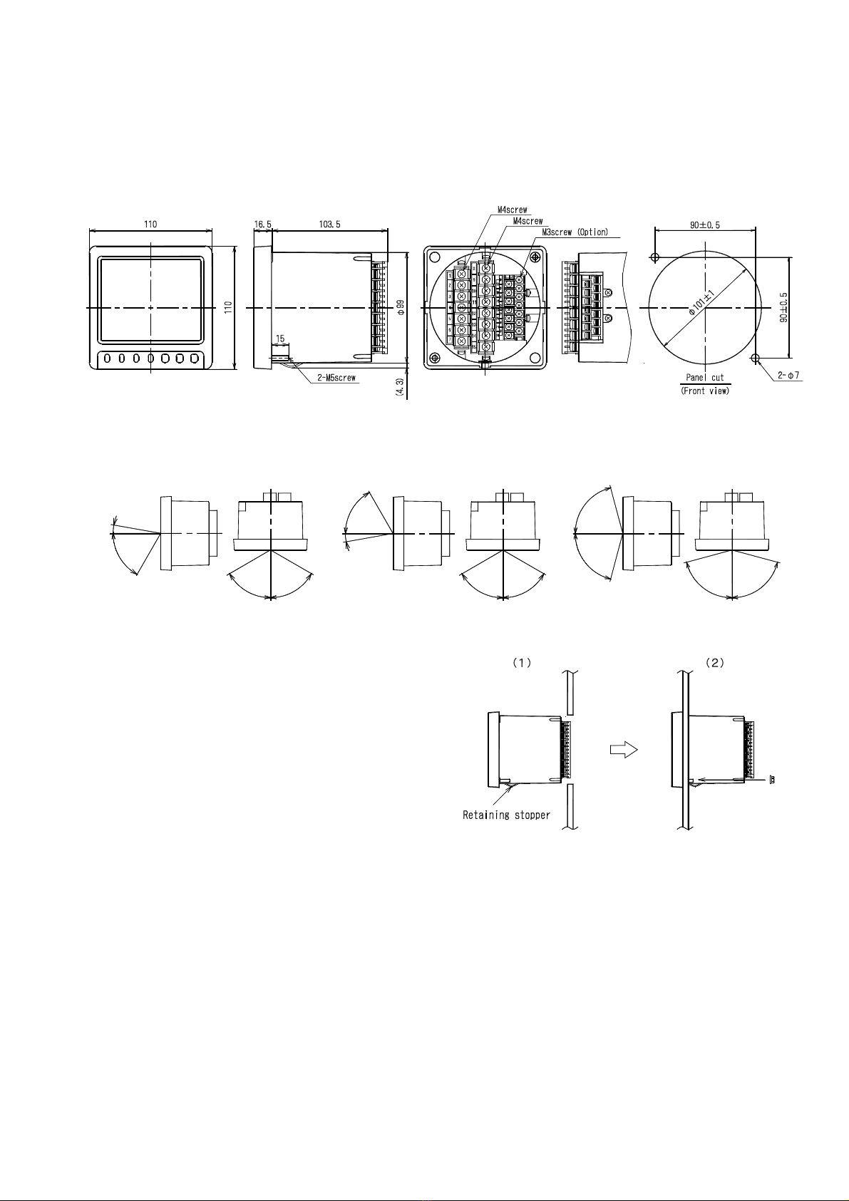
Mounting and wiring
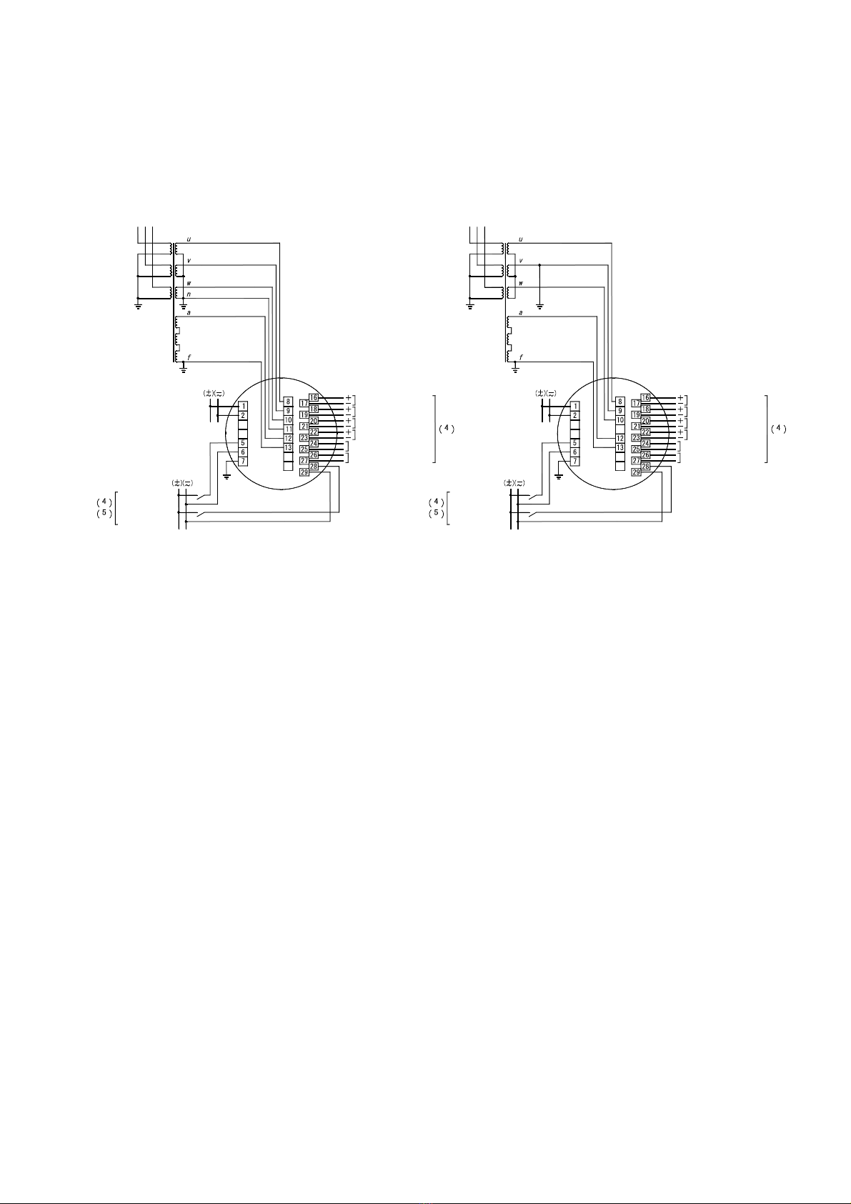
Please refer to this instruction manual for mounting and the wiring.
Please refer to connection diagram for the wiring.
Please avoid a hot line work.
Please use an electrical wire size suitable with the rated current.
Please check the tightening of the screw.
Preparation
This product must be set before use. Please set correctly after reading this instruction manual.
About dew condensation
If the temperature and humidity of an installation change rapidly when a product is a non-energization, the waterdrop
by dew condensation may adhere to a display inner side. (The display filter and the LCD surface stick and the pattern
of the shape of a circle or an ellipse occur.)
This phenomenon does not cause any trouble. Disappears when control power is applied for 2 hours.
Maintenance and inspection
Inspection in energized state is dangerous.
No replacement in periodic inspection.
After wiring change and maintenance, attach the terminal cover.
Please wipe off lightly with the dry soft cloth. Please do not use the organic solvent, chemicals, cleaners, etc.,
such as an alcohol, for cleaning.
The LCD may light up during cleaning on the LCD screen. This is a phenomenon that static electricity occurs in
the filter. There is no problem with the product. Leave the unit as it is for a while, and the display goes out
due to natural discharge.
Do not press the LCD screen strongly. Pressing the LCD screen may cause the filter and the liquid crystal surface
to remain in contact (such as a round pattern).
Storage
Please store in a place that meets the following conditions.
The ambient temperature is within -25 to +70 ℃ (storage temperature).
Daily average temperature 40 ℃ or less.
Location corresponding to the usage environment and use conditions.
Aluminum electrolytic capacitors are used for products. Please energize the power supply within one year after
purchase.
Countermeasures against troubles.
If this product breaks down within the warranty period, it will be repaired by DAIICHI ELECTRONICS.