IOM 1206-13 • TRAILBLAZER®MODEL AGZ CHILLERS 6 www.DaikinApplied.com
General Description
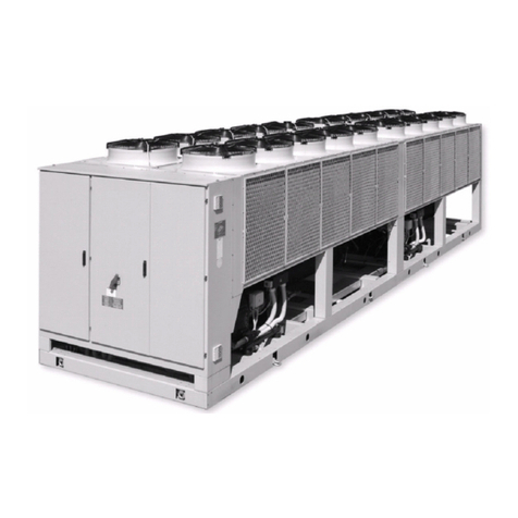
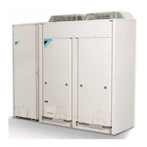
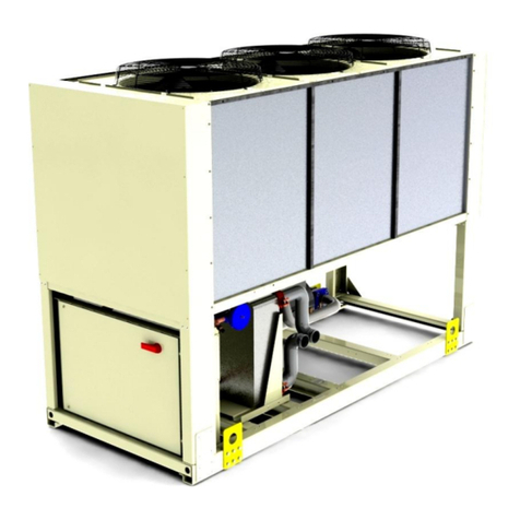
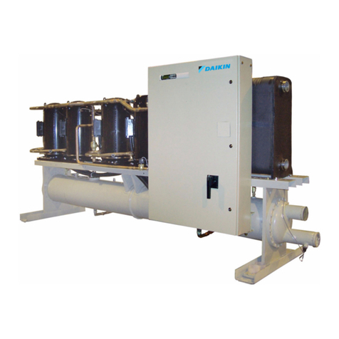
Daikin Trailblazer®air-cooled water chillers are complete, self-
contained, automatic chillers designed for outdoor installation.
Packaged units are completely assembled, factory wired,
charged, and tested.
The electrical control center includes all equipment protection
and operating controls necessary for dependable automatic
operation. Components housed in a centrally located, weather
resistant control panel with hinged and tool-locked doors.
NOMENCLATURE
A G Z XXX E D SE
Table 1: Operating Limits for AGZ-E Chillers
Maximum standby ambient temperature 130°F (54°C)
Maximum operating ambient temperature 105°F (41°C)
-with optional high ambient package (see information under High Ambient Operation) 125°F (52°C)
Minimum operating ambient temperature (standard control) 32°F (0°C)
Minimum operating ambient temperature (with optional low-ambient control) -10°F (-23°C)
Leaving chilled water temperature 40°F to 65°F (4°C to 18°C)
Leaving chilled uid temperatures (with anti-freeze) - Note that in cases of high ambient
temperature, the lowest leaving water temperature settings may be outside of the chiller
operating envelope; consult Daikin Tools to ensure chiller is capable of the required lift.
15°F to 65°F (-9°C to 18°C)
Operating chilled water delta-T range 6°F to 16°F (3.3°C to 8.9°C)
Maximum evaporator operating inlet uid temperature 81°F (27°C)
Maximum evaporator non-operating inlet uid temperature 100°F (38°C)
Nameplates
Identication nameplates on the chiller:
• The unit nameplate is located on the exterior of the Unit
Power Panel. Both the Model No. and Serial No. are
located on the unit nameplate; the Serial No. is unique to
the unit. These numbers should be used to identify the
unit for service, parts, or warranty questions. This plate
also has the unit refrigerant charge and electrical ratings.
• Evaporator data plate is under insulation and contains
the serial number.
• Compressor nameplate is located on each compressor
and gives pertinent electrical information.
Installation is to be performed by qualied personnel who are
familiar with local codes and regulations.
CAUTION
Sharp edges and coil surfaces are a potential injury hazard.
Avoid contact with them.
Inspection
Check all items carefully against the bill of lading. Inspect
all units for damage upon arrival. Report shipping damage
and le a claim with the carrier. Check the unit nameplate
before unloading, making certain it agrees with the power
supply available. Daikin Applied is not responsible for physical
damage after the unit leaves the factory.
Handling
Be careful to avoid rough handling of the unit. Do not push or
pull the unit from anything other than the base while sitting on
appropriately-sized roller dollies.
To lift the unit, 2-1/2” (64mm) diameter lifting eyes are provided
on the base of the unit. Arrange spreader bars and cables to
prevent damage to condenser coils or cabinet (see Figure 1).
CAUTION
All lifting locations must be used to prevent damage to unit.
Air-Cooled
Global Design
Scroll Compressor
Application, Eciency, Unit Type
Design Vintage
Nominal Tons # of Compressors
D = Tandem per Circuit
T = Trio per Circuit
