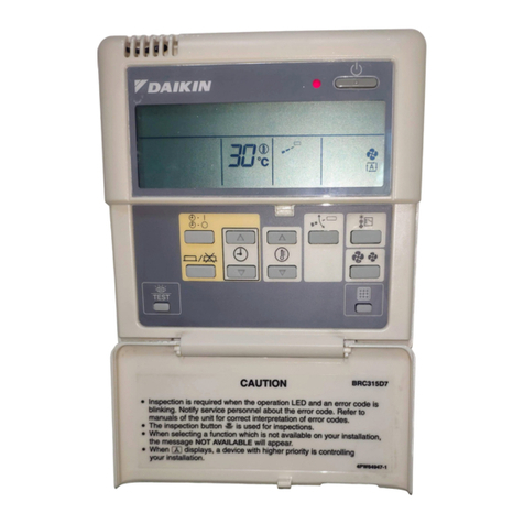
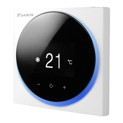
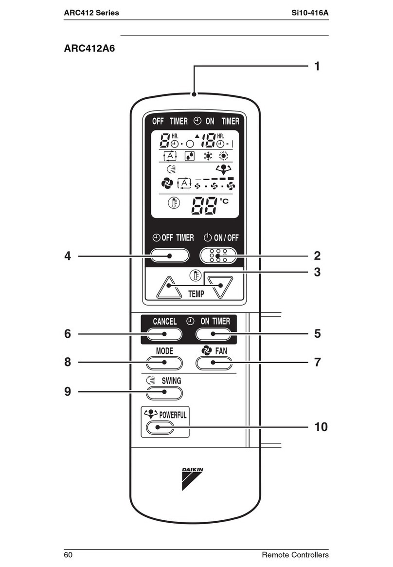
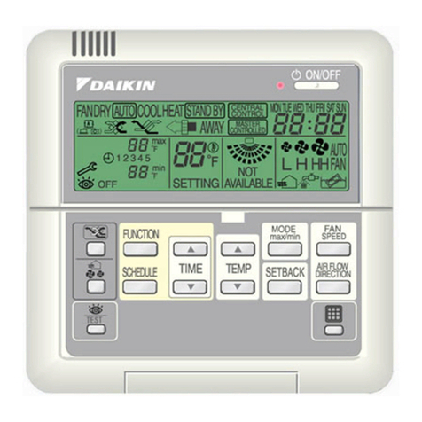
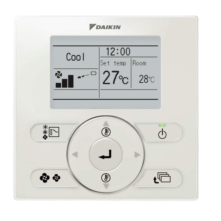
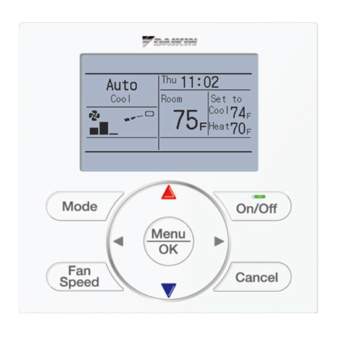
Daikin BRC2E61 User manual

WIRED REMOTE
CONTROLLER
Installation and Operation manual
• Thank you for purchasing this product.
• This manual describes safety precautions required for the use of the product.
Read this manual carefully and be sure you understand the
information before installing and using the product.
Keep this manual where it is readily accessible after reading it through.
If another user operates the product in the future, be sure to hand over this
manual to the new user.
Refer to the installation and operation manuals attached to the indoor and
outdoor units, etc.
BRC2E61
00_CV_4P543053-1C.indd 1 07/05/2019 17:38:36

Disposal requirements
Your product and the batteries supplied with the
controller are marked with this symbol. This symbol
means that electrical and electronic products and
batteries shall not be mixed with unsorted household
waste.
For batteries, a chemical symbol can be printed beneath
the symbol. This chemical symbol means that the battery
contains a heavy metal above a certain concentration.
Possible chemical symbols are:
Pb: lead (>0.004%)
Do not try to dismantle the system yourself: the
dismantling of the product, treatment of the refrigerant, of
oil and of other parts must be done by a qualied installer
in accordance with relevant local and national legislation.
Units and waste batteries must be treated at a
specialized treatment facility for re-use, recycling and
recovery.
By ensuring correct disposal, you will help to prevent
potential negative consequences for the environment
and human health.
Please contact the installer or local authority for more
information.
00_CV_4P543053-1C.indd 2 07/05/2019 17:38:37

1
CONTENTS
1. Safety precautions .................................................. 2
For the installer ........................................................................... 2
For the user................................................................................. 4
2. Accessories ............................................................. 5
3. Button locations and descriptions ........................ 5
4. Names and functions .............................................. 6
4.1 Basic screen....................................................................... 6
For the installer
5. Remote controller installation procedure ............. 8
6. Power-on ................................................................ 13
7. Field settings ......................................................... 14
8. Test operation method
(in the case of SPLIT system)............................... 17
9. Connection diagram.............................................. 19
For the user
10. Basic operation...................................................... 21
10.1 Cool/Heat/Auto/Fan operation .......................................... 21
10.2 Dry operation.................................................................... 24
10.3 Setting the Cool/Heat selection eligibility (VRV only) ....... 25
10.4 Program timer operation................................................... 28
11. Maintenance........................................................... 30
11.1 Cleaning of the remote controller ..................................... 30
12. Reference Information........................................... 31
12.1 Malfunction (Error) code display....................................... 31
12.2 After-sales service............................................................ 31
01_EN_4P543053-1C.indd 1 10-May-19 4:13:13 PM

2
1.
Safety precautions
Also refer to the installation and operation manuals attached to the
indoor unit.
Please read these “Safety precautions” carefully before installing and
using the remote controller.
• Thisproductisnotintendedforusebychildrenorinrmpersonswithoutsupervision.
Childrenshouldbesupervisedtoensurethattheydonotplaywiththeproduct.
• ThismanualclassiestheprecautionsintoWARNINGSandCAUTIONS.
Besuretofollowalltheprecautionsbelow:Theyareallimportantforensuringsafety.
WARNING Indicatesapotentiallyhazardoussituationwhich,ifnotavoided,could
result in death or serious injury.
CAUTION
Indicatesapotentiallyhazardoussituationwhich,ifnotavoided,may
result in minor or moderate injury.
Itmayalsobeusedtoalertagainstunsafepractices.
For the installer
• Aftercompletinginstallation,conductatestoperationtocheckforfaultsandexplaintothecustomer
howtooperatetheremotecontrollerandcleaningofitwiththeaidoftheoperationmanual.Askthe
customertostoretheinstallationmanualalongwiththeoperationmanualforfuturereference.
WARNING
Askyourlocaldealerorqualiedpersonneltocarryoutinstallationwork.
Do not attempt to install the remote controller yourself.
Improperinstallationmayresultinelectricshockorare.
Consult your local dealer regarding relocation and reinstallation of the remote controller.
Improperinstallationmayresultinelectricshockorare.
Installtheremotecontrollerinaccordancewiththeinstructionsinthisinstallationmanual.
Improperinstallationmayresultinelectricshockorare.
Besuretouseonlythespeciedaccessoriesandpartsforinstallationwork.
Failuretousethespeciedpartsmayresultintheremotecontrollerfallingdown,electricshockorare.
Installtheremotecontrolleronafoundationthatcanwithstanditsmass.
Insufcientstrengthmayresultintheremotecontrollerfallingdownandcausinginjury.
Makecertainthatallelectricalworkiscarriedoutbyqualiedpersonnelaccordingtotheapplicable
legislation(Note1)andthisinstallationmanual,usingaseparatecircuit.
Inaddition,evenifthewiringisshort,makesuretouseawiringthathassufcientlengthandnever
connectadditionalwiringtomakethelengthsufcient.
Insufcientcapacityofthepowersupplycircuitorimproperelectricalconstructionmayleadto
electricshockorare.
(Note1)
applicablelegislationmeans“Allinternational,nationalandlocaldirectives,laws,regulations
and/orcodeswhicharerelevantandapplicableforacertainproductordomain”.
Turnoffthepowerbeforeperforminginstallationwork.
Touchwithlivepartsmaycauseelectricshock.
01_EN_4P543053-1C.indd 2 10-May-19 4:13:13 PM

3
WARNING
Donotdisassembly,reconstructorrepair.
Electricshockoraremaycause.
Makesurethatallwiringissecured,usingthespeciedwiringsandensuringthatexternalforcesdo
notactontheterminalconnectionsorwirings.
Improperconnectionsorxingmaycauseanoverheatorare.
Thechoiceofmaterialsandinstallationsmustcomplywiththeapplicablenationalandinternational
standards.
CAUTION
Toavoidelectricshockduetoentryofwaterorinsects,llthewiringthroughholewithputty.
Donotoperatewithwethandstoavoidelectricshock.
Donotwashtheremotecontrollerwithwater.
Itmayresultinelectricshockorare.
Installtheairconditioner,powersupplywiring,remotecontrollerwiringandtransmissionwiringat
least1meterawayfromtelevisionsorradiostopreventimageinterferenceornoise.
(Dependingontheradiowaves,adistanceof1metermaynotbesufcienttoeliminatethenoise.)
Donotinstalltheremotecontrollerinthefollowinglocations:
1.Wherethereisoilmist,oilsprayorvapourforexampleakitchen.
Resin parts may deteriorate and fall off.
2.Wherecorrosivegas,suchassulfurousacidgas,isproduced.
3.Wherethereismachinerywhichemitselectromagneticwaves.
Electromagneticwavesmaydisturbthecontrolsystem,andcauseamalfunctionofthe
equipment.
4.Whereammablegasmayleak,wherethereiscarbonbreorignitabledustsuspensions
intheair,orwherevolatileammablessuchasthinnerorgasolinearehandled.
Operatingtheunitinsuchconditionsmayresultinare.
5.Hightemperatureareaordirectlyamedpoint.
Itmaycauseanoverheatorare.
6.Moistarea,orplacewheremaybeexposedtowater.
Ifwaterentersinsideoftheremotecontroller,electricalcomponentsmayfail.
Itmayresultinelectricshockorare.
Whenremotecontroller’sthermostatsensorisused,selecttheinstallationlocationconsideringthe
followings.
• Aplacewhereaveragetemperatureintheroomcanbedetected.
• Aplacewhereisnotexposedtodirectsunlight.
• Aplacewhereisfarapartfromheatsource.
• Aplacewhereisnotaffectedbyoutdoorairduetodooropening/closingorthelike.
01_EN_4P543053-1C.indd 3 10-May-19 4:13:13 PM

4
For the user
WARNING
Do not install the remote controller by yourself.
Improperinstallationmayresultinelectricshockorare.
Consult your local dealer.
Do not modify or repair the remote controller.
Itmayresultinelectricshockorare.
Consult your local dealer.
Do not relocate or reinstall the remote controller by yourself.
Improperinstallationmayresultinelectricshockorare.
Consult your local dealer.
Donotuseammablematerialssuchashairsprayorinsecticideneartheproduct.
Itmayresultinelectricshockorare.
Donotwipetheproductwithbenzine,thinner,chemicaldustcloth,etc.
The product may get discolored or the coating peeled off.
Theuseoforganicsolventsmaycausecrackingoftheproduct,electricshockorare.
CAUTION
Donotallowchildrentoplaywiththeremotecontroller.
Accidental operation by children may result in health impairment.
Do not disassemble the product.
Touchingtheinteriorpartsmayresultinelectricshockorare.
Consult your local dealer for internal inspections and adjustments.
Donotpressthebuttonoftheremotecontrollerwithahard,pointedobject.
The remote controller may be damaged.
Donotpullortwisttheelectricwireoftheremotecontroller.
Itmaycausetheunittomalfunction.
Donotoperatewithwethandstoavoidelectricshockorare.
Donotwashtheremotecontroller.
Itmaycauseelectricleakageandresultinelectricshockorare.
Donotlocatetheremotecontrollerwhereverthereisariskofwetting.
Ifwatergetsintotheremotecontrollerthereisariskofelectricleakageanddamagetoelectronic
components.
Itmayresultinelectricshockorare.
01_EN_4P543053-1C.indd 4 10-May-19 4:13:13 PM
5
2.
Accessories
Thefollowingaccessoriesareincluded.
Wiredremotecontroller Woodscrew Smallscrew Installation&Operationmanual
(M3.5 × 16) (M4 × 16)
(1 pc.) (1 pc.) (2 pcs.) (2 pcs.) (1 pc.)
3.
Button locations and descriptions
1. ON/OFF button
2. Operation lamp
(Green)
6. Temperature
Setting button
7. Air ow Direction
Adjustment button
3. Mode Selector
button
4. Display (LCD)
5. Fan Speed Control
button
1. ON/OFF button
• Pressthisbuttonandthesystemwillstart.
• Pressthisbuttonagainandthesystemwill
stop.
2. Operation lamp (Green)
• This lamp lights up during operation.
• Thislampblinksifamalfunctionoccurs.
3. Mode Selector button
Press this button to select the operation mode
of your preference.
•
Availablemodesvarywiththeconnectedmodel.
4. Display (LCD)
Showsthestatusanddetailofoperation.
5. Fan Speed Control button
Press this button to select the fan speed of
your preference.
6. Temperature Setting button
Press this button to set the temperature.
:Eachpressraisesthe
set temperature by 1°C
:Eachpresslowersthe
set temperature by 1°C
The variable temperature range is 16°C to 32°C.
7. Air ow Direction Adjustment
button
Pressthisbuttontoadjusttheairowdirection
(orapposition).
• Ifswingmodeisnotavailableonthemodel
(Ductmodelforexample),“ ”
maybedisplayedfor3secondswhenthis
button is pressed.
01_EN_4P543053-1C.indd 5 10-May-19 4:13:15 PM

6
4.
Names and functions
4.1
Basic screen
1
4
5
2
3
6
7
1. DISPLAY “ ” (CHANGEOVER
UNDER CONTROL)
ItisimpossibletochangeoverHeat/Coolwith
theremotecontrollerwhenitshowsthis
display.(Asfordetails,see“SETTINGOF
MASTERREMOTECONTROLLER”inthe
operation manual attached to the indoor unit.)
2. DISPLAY “ ” “ ” “ ” “ ” “ ”
(OPERATION MODE)
ThisdisplayshowscurrentOPERATION
MODE.“ ”isnotavailableinoutdoorunits
specially designed for cooling only.
“ ”isreservedonlyforoutdoorunits
capable of heat recovery.
3. DISPLAY “ ” (MALFUNCTION)
Indicatesmalfunctionandblinksiftheunit
stops operating due to malfunction.
(Asfordetails,see“TROUBLESHOOTING”in
the operation manual attached to the indoor
unit.)
4. DISPLAY “ ” (NON
FUNCTION DISPLAY)
Iftheparticularfunctionisnotavailable,
pressingthebuttonmaydisplaythewords
“ ”forafewseconds.
Whenrunningmultipleunitssimultaneously,
the “ ”messagewillonlybe
appearifnoneoftheindoorunitsisequipped
withthefunction.Ifevenonunitisequipped
withthefunction,thedisplaywillnotappear.
5. DISPLAY “ ” (SET
TEMPERATURE)
Thisdisplayshowsthesettemperature.Only
given during a Cooling operation or Heating
operation.
6. DISPLAY “ ” (DEFROST/
HOT START)
Indicatesthatdefrostorhotstart(duringwhich
the fan is stopped until the temperature of air
supply rises enough at the start of a Heating
operation) is in progress.
7. DISPLAY “ ” (UNDER
CENTRALIZED CONTROL)
Whenthisdisplayshows,thesystemis
UNDERCENTRALIZEDCONTROL.
(Thisisnotastandardspecication)
01_EN_4P543053-1C.indd 6 10-May-19 4:13:17 PM

7
8
10
12
13
11
9
8. DISPLAY “ ” (UNIT NO.
MODE)
Duringeldsetting(settingperindoorunit
duringgroupcontrolfunction),thedisplay
showstheselectedunitno.
9. DISPLAY “ ” (VENTILATION/
AIR CLEANING)
Thisdisplayshowsthatthetotalheat
exchangeandtheaircleaningunitarein
operation. (These are optional accessories).
10. DISPLAY “ ” (AIRFLOW
RATE [AIRFLOW LEVEL/FAN
SPEED])
Thedisplayshowstheairowrate[Lv.1,Lv.2,
Lv.3,Lv.4,Lv.5andAuto]thatissetforthe
indoor unit.
Theairowratewillnotbedisplayedifthe
indoorunitdoesnothaveairowratecontrol
function and the number of available fan
speeds may differ depending on the indoor
unitspecications.
11. DISPLAY “ ” (AIRFLOW
DIRECTION)
Thedisplayshowswhentheairowdirection
andswingareset.Thisiconisnotdisplayedif
the indoor unit does not have a function to set
airowdirections.
12. DISPLAY “ ” (TIMER MODE
ON/OFF)
Thedisplayshowswhenthetimerfunctionof
theremotecontrollerissettoON/OFF.
13. DISPLAY “ ” (GROUP
NO.)
Duringeldsetting,thedisplayshowsthe
mode no. function concerned.
01_EN_4P543053-1C.indd 7 10-May-19 4:13:18 PM

8
For the installer
5.
Remote controller installation procedure
1) Determine where to install the remote controller.
Makesuretofollow“1. Safety precautions”whendeterminingthelocation.
2) Determine the direction of controller wiring outlet
(Top right outlet, Right outlet, Bottom centre outlet).
1) Top right outlet
2) Right outlet 3) Bottom centre outlet
Cutawaythethinarea(hatchedarea)with
nippersorthelikeandthenremoveburrs
withaleorthelike.
Cutawaythethinarea(hatchedarea)with
nippersorthelikeandthenremoveburrs
withaleorthelike.
Cutawaythethinarea(hatchedarea)with
nippersorthelikeandthenremoveburrs
withaleorthelike.
Front side
Front side Front side
Backside
Backside Backside
01_EN_4P543053-1C.indd 8 10-May-19 4:13:19 PM

9
3) Conduct wiring
1.Switchboxandtransmissionwiringarenotattached.
2. Do not directly touch the PCB (Printed Circuit Board).
CAUTION
Wiringspecications
WiringType Sheathed vinyl cord or cable (2 cores) (*1)
WiringSize 0.75~1.25 mm2
WiringLength Max.500m(*2)
* 1.Somecountriesmayrequireashieldedwiring.
Refer to the installation manual attached to the indoor unit.
* 2.Thiswillbethetotalextendedlengthinthesystemwhendoinggroupcontrol.
Preparethewiringforconnectiontotheremotecontrollerfollowingtheseinstructions.
Approx.10mm
Foreasywiring,itisbetterto
keepapprox.10mmdifference
betweenthelengthof2wires.
Cutting guideline
ofthewiring
Peel the insulator and sheath
Sheathstrippinglength:
• Approx.135mmfortoprightoutlet
• Approx.125mmforrightoutlet
• Approx.105mmforbottomcentreoutlet
Connecttheterminals(P/P1,N/P2)oftheremotecontrollertotheterminals(P1,P2)oftheindoor
unit. (P1 and P2 have no polarities.)
Top right outlet
P1 P2
Uppercase Lowercase
Indoorunit
01_EN_4P543053-1C.indd 9 10-May-19 4:13:20 PM

10
Right outlet
Uppercase Lowercase
Indoorunit
P1 P2
Bottom centre outlet
Uppercase Lowercase
Indoorunit
P1 P2
Performthewiringatadistancefromthepowerlinesoasnottoreceiveelectricalnoise
(externalnoise).
CAUTION
01_EN_4P543053-1C.indd 10 10-May-19 4:13:20 PM

11
4) Fix the lower case to a wall.
IncaseofwiringaremotecontrollerthroughToprightoutlet,Rightoutlet,orBottomcentreoutlet,
performwiringthoughtheoutletholeinthelowercasebeforeinstallingonthewall.
Securebyusingtheattachedwoodscrews(2pcs.)orsmallscrews(2pcs.).Fixthetopscrew
holerst,thenxthebottomscrewhole.
Woodscrews(M3.5×16)
orSmallscrews(M4×16)
• Selectasataplaceaspossiblefortheinstallationface.
• Donottightentheinstallationscrewstoomuchsoasnottodeformthelowercase.
CAUTION
01_EN_4P543053-1C.indd 11 10-May-19 4:13:20 PM

12
5) Install the upper case in the original position.
•
Aligntheuppercasewiththetabsonthelowercase(4points),theninsertandinstalltheuppercase.
Carefullycheckthatthereisnogapbetweentheupperandlowercaseswhentheyareclosed.
Nogap
Good Wrong
There is a gap.
Ifthereisagap,removetheuppercaseandrearrangewireharnesspositionthenreinstall
theuppercase.(Fortheremovalmethodoftheuppercase,seethenote.)
• Installthewiringwithcaretopreventpinching.
• Peelofftheprotectivesheetwhichisattachedtotheuppercase.
Note:
When removing the upper case
Insertascrewdriverintherecessoflowercasetoremovetheuppercase(2points).
Remote controller PCB is installed
on the upper case.
TakecarenottodamagethePCB
withthescrewdriver.
Takecarethatdustormoisturedoes
not touch the PCB.
Uppercase
Lowercase
Screwdriver
Insertandtwistthe
screwdriverlightlyforremoval.
01_EN_4P543053-1C.indd 12 10-May-19 4:13:21 PM

13
6.
Power-on
• Checkforcompletionofindoor/outdoorunitswiring.
• Checkforclosingofcontrolboxlidofindoorandoutdoorunitsbeforeturningonthepower.
• When1indoorunitiscontrolledby2remotecontrollers.
BesuretosetthesubremotecontrollerbychangingtheSS1switchonthesideofthePCBfromthe
MASTERtotheSLAVEposition.
Fortheconnectionbetweenthemainremotecontrollerandsubremotecontroller,pleasereferto
Connection diagram “Group control: main controller + sub controller”onpage20.
SS1MASTERSLAVE
SS1MASTERSLAVE
SS1MASTERSLAVE
(1) (2)
(1)Factoryset:MASTER (2)MovetoSLAVE
1) “ ”isdisplayedafterturningonthepower.
Theairconditionerwillchecktheconnection.
• Iferrorsaredetected,therelevanterrorcodeblinkson
the screen. Please see more details about error codes
athttps://www.daikin.co.th/en/service-error-code
Aftercorrectingtheerror,thebasicscreenisdisplayed.
• Ifsubremotecontrollerisnotsetwhenturningonthe
powerinthecaseofindoorunitscontrolledby
2 remote controllers.
Incasethescreendisplayshows“ ”,turnoffthe
poweroftheremotecontrollerandbreakerofair
conditioner.ThenchangetheSS1switchfromthe
MASTERtotheSLAVEpositionasdescribedabove,
thenturnonthepoweragain.
Ifthebasicscreenisnotdisplayedmorethan
2minutesafterthesubremotecontrollerisset,turn
offthepoweragainandcheckthewiring.
Incasethescreendisplayshows“ ”formore
than2minutes,turnoffthepoweroftheremote
controllerandbreakerofairconditioner.Then,
pleasemakesuretheswitchSS1positionofmain
remote controller is MASTER and the sub remote
controllerisSLAVE.
2) Whennoerrorsaredetected,thebasicscreenis
displayed.
1)
2)
*Errorcodeblinks
[Main/Sub remote controller]
[Basic screen]
01_EN_4P543053-1C.indd 13 10-May-19 4:13:21 PM

14
7.
Field settings
1) Press and hold both the Mode
Selector button ( ) and the
TemperatureSetting(down)button
( ) for 4 seconds or longer.
2) Selectthedesired“ModeNo.”by
usingtheAirowDirection
Adjustment button ( ).
Forcommonlyusedeldsetting
items,refertothetableonpage16.
3) Inthecaseofsettingperindoorunit
duringgroupcontrol(whenaMode
No.suchas20,21,22,23or25is
selected),selectthe“IndoorunitNo.”
to be set by using the Fan Speed
Control button ( ).(Inthecaseof
groupsetting,thisoperationisnot
needed.)
4) SelecttheFIRSTCODENO.tobe
changed by using the Temperature
Setting (up) button ( ) and
SECONDCODENO.tobechanged
by using the Temperature Setting
(down)button( ).
Multiple identical mode number
settings are available.
5) Press the Mode Selector button
( ).
Field setting mode is set.
6) Inthecaseofmultiplesetting
changes,repeat2) to 4).
Press and hold
2 buttons for
4 seconds or longer.
Field setting mode is set
1)
2)
3)
4)
5)
[Basic screen]
[Field setting mode screen]
FIRSTCODENO.
4)
SECONDCODENO.
01_EN_4P543053-1C.indd 14 10-May-19 4:13:23 PM

15
7)
Afterallsettingchangesarecompleted,
press both the Mode Selector button
( ) and the Temperature Setting
(down)button( ) for 1 second.
“ ”isdisplayedduringinitialization.
8) Aftertheinitialization,thebasic
screen returns.
7)
8)
[Initialization screen]
[Basic screen]
•
Whenanoptionalaccessoryisinstalledontheindoorunit,settingsoftheindoorunitmaybe
changed. Refer to the manual of the optional accessory.
•
Foreldsettingdetailsoftheoutdoorunit,refertotheinstallationmanualattachedtotheoutdoor
unit.
CAUTION
01_EN_4P543053-1C.indd 15 10-May-19 4:13:23 PM

16
[Commonly used eld setting items]
ModeNo.
Note1)
FIRST
CODENo.
Description of setting
SECONDCODENo.
01 02 03
10(20)
0
Note3)
FilterContamination-Heavy/Light
(Setting for spacing time of display
timetocleanairlter)
(Settingforwhenltercontamination
isheavy,andspacingtimeofdisplay
timetocleanairlteristobehalved)
Ultra-long-
life type
Light
Approx.
10,000Hrs
Heavy
Approx.
5,000Hrs
–
Longlife
Filter
Approx.
2,500Hrs
Approx.
1,250Hrs
Standard
Filter
Approx.
200 Hrs
Approx.
100 Hrs
1
Note3)
Long-lifeltertype
(Settingofltersignindicationtime)
(ChangesettingwhenUltra-long-lifelteris
installed)
Long-life
lter
Ultra-long-
lifelter –
2 Thermostat sensor in remote controller Use Notuse –
11(21) 0
SettingnumberofconnectedSkyairsimultaneous
operation System indoor unit
(Setting for Simultaneous operation system)
Pair Twin –
12(22) 1 ON/OFFinputfromoutside ForcedOFF ON/OFF
operation –
13(23)
0
HighCeilingSetting(Settingforwheninstalledin
a Ceiling higher than 2.7m)
* Height depends on the connected model.
Refer to the installation manual attached to the
indoor unit to be connected for details.
≤2.7m* 2.7m<,
≤3.0m*
3.0m<,
≤3.5m*
1
SelectionofAirowDirection
(Settingforwhenablockingpadkithasbeen
installed)
4-wayow 3-wayow 2-wayow
3
AirowDirectionAdjustmentFunction
(Tobesetwhendecorationpanelforairoutlet
installed)
Equipped No
Equipped –
4AirowDirectionRangeSetting Upper Normal Lower
6
SettingtheExternalStaticpressure
(Setting according to the connected duct
resistance)
(ForFHYK,followthehighCeilingSetting)
Normal High static
pressure
Lowstatic
pressure
15(25)
1HumidifyingwiththermostatOFF No
Equipped Equipped –
3Drainpumpoperationwithhumidifying No
Equipped Equipped –
Note:
1)Incasethereisaneedtoperformanysettingnotlistedinthetableabove,pleaserefertothe
installation manual of each indoor unit.
2)Somefunctionswillbenotdisplayediftheindoorunitisnotequippedwiththatfunction.
3)Thismodeisusedtosetthetimeuntilthedisplaytimetocleanairlterlightsupwhenusinga
central remote controller.
01_EN_4P543053-1C.indd 16 10-May-19 4:13:23 PM

17
8.
Test operation method (in the case of
SPLIT system)
• InthecaseofVRVsystem,refertothemanualattachedtotheoutdoorunit.
Also refer to the installation manuals attached to the indoor unit and the outdoor unit.
• Checkthatwiringworkoftheindoorunitandtheoutdoorunitiscompleted.
• Checkthatcontrolboxlidoftheindoorunitandtheouterpanelandpipingcoveroftheoutdoorunit
are closed.
• Afterrefrigerantpiping,drainpipingandelectricwiringarecompleted,cleantheinsideoftheindoor
unit and decoration panel.
• Performthetestoperationaccordingtofollowingprocedure.
1) Toprotectthecompressor,turnonthe
powertotheoutdoorunitatleast6
hours prior to test operation.
2) Conrmthatstopvalvesofbothliquid
side and gas side are opened.
Makesurethatouterpanelandpiping
cover are closed before operation (danger
ofelectricshock).
CAUTION
•
Afterairpurgebyvacuumpump,
refrigerant pressure may not rise even
though the stop valve is opened. The
reason is that refrigerant system of the
outdoorunitisblockedbyelectric
expansionvalveorthelike.
Operationisnoproblem.
3) Press the Mode Selector button ( ) to
select Cool mode.
4)
Press and hold 3 buttons --the Mode
Selector button ( ),theAirowDirection
Adjustment button ( ),andthe
Temperature Setting (up) button ( )-- for
4 seconds or longer to enter Test
operation.
“ ”isdisplayedonthebasicscreen.
3)
[Basic screen]
4)
3)
4)
Press and hold
3 buttons for
4 seconds or longer.
01_EN_4P543053-1C.indd 17 10-May-19 4:13:24 PM

18
5)
Checktheoperationstatusoftheremote
controllerbycheckingifthegreenlampon
theON/OFFbuttonlightsupornot.
• IftheremotecontrollerisON(Green
lamplightsup),continuetostep6).
•
IftheremotecontrollerisOFF(Green
lampdoesn’tlightup),presstheON/
OFFbuttonwithin10secondsafter
“ ”isdisplayedonthebasic
screen.
6) Checktheoperationofthebuttonsby
pressingthefollowingbuttons
• PresstheAirowDirection
Adjustment button (
) for setting
airow.
• Press the Mode Selector button
( ) for setting operation mode.
• Press the Fan Speed Control button
(
) for setting fan speed.
7) Press and hold 3 buttons --the Mode
Selector button ( ),theAirow
Direction Adjustment button ( ),
and the Temperature Setting (up) button
( ).
The basic screen returns and normal
operation is conducted.
Note:
Testoperationwillautomaticallynishin
30 minutes.
8) Checkthefunctionsaccordingto
“10. Basic operation”.
9) Whenthedecorationpanelisnot
installed,turnoffthepowerafterthetest
operationnishes.
5)
7)
[Basic screen]
•
Iftheinteriornishworkisnotcompletedwhenthetestoperationisnished,forprotectionoftheair
conditioneraskthecustomernottooperatetheairconditioneruntiltheinteriornishworkis
completed.
Iftheairconditionerisoperated,theinsideoftheindoorunitsmaybepollutedbysubstances
generatedfromthecoatingandadhesivesusedfortheinteriornishworkandcausewatersplash
andleakage.
CAUTION
01_EN_4P543053-1C.indd 18 10-May-19 4:13:25 PM
Table of contents
Other Daikin Remote Control manuals

Daikin
Daikin BRC1H71W System manual

Daikin
Daikin Madoka BRC1H82K User guide

Daikin
Daikin MicroTech II User manual

Daikin
Daikin BRC1D61 User manual

Daikin
Daikin BRC1H51W User guide

Daikin
Daikin BRC1H519W7 User guide

Daikin
Daikin BRC51D64 User manual

Daikin
Daikin BRC1E73 User manual

Daikin
Daikin DCS302C71 User manual

Daikin
Daikin BRC1E52A7 User manual

Daikin
Daikin BRC1D52 User manual

Daikin
Daikin BRC1H71W User manual

Daikin
Daikin BRC1H81W7 User guide

Daikin
Daikin Madoka User manual

Daikin
Daikin BRC1H71W User manual

Daikin
Daikin BRC51D61 User manual

Daikin
Daikin BRC1D619 User manual

Daikin
Daikin BRC1E62 User manual

Daikin
Daikin BRC1E51 User manual

Daikin
Daikin Madoka User manual