EWWP045~065KAW1M + ECB1~3MUW
Packaged water-cooled water chillers
4PW30041-1A
Operation manual
4
Safety devices
■
Overcurrent relay
The overcurrent relay (K*S) is located in the switch box of the
unit and protects the compressor motor in case of overload,
phase failure or too low voltage.The relay is factory-set and may
not be adjusted. When activated, the overcurrent relay has to be
reset in the switch box and the controller needs to be reset
manually.
■
High-pressure switch
The high-pressure switch (S*HP) is installed on the discharge
pipe of the unit and measures the condenser pressure (pressure
at the outlet of the compressor). When the pressure is too high,
the pressure switch is activated and the circuit stops.
When activated, it resets automatically, but the controller needs
to be reset manually.
■
Low pressure switch
The low-pressure switch (S*LP) is installed on the suction pipe
of the unit and measures the evaporator pressure (pressure at
the inlet of the compressor). When the pressure is too low, the
pressure switch is activated and the circuit stops.
When activated, it resets automatically, but the controller needs
to be reset manually.
■
Reverse phase protector
The reverse phase protector (R1P) is installed in the switch box
of the unit. It prevents the compressor from running in the wrong
direction. If the unit does not start, two phases of the power
supply must be inverted.
■
Discharge thermal protector
The discharge thermal protector (Q*D) is activated when the
temperature of the refrigerant leaving the compressor becomes
too high. When the temperature returns to normal, the protector
resets automatically, but the controller needs to be reset
manually.
■
Freeze-up protection
The freeze-up protection prevents the water in the evaporator
from freezing during operation. When the outlet water
temperature is too low, the controller disables the circuit. When
the outlet water temperature returns to normal, the circuit can
start up again.
When freeze-up protection occurs several times in a certain
period, the freeze-up alarm will be activated and the circuit will
be shut down. The cause of freezing up should be investigated
and after outlet water temperature has risen enough, the alarm
indicator on the controller needs to be reset manually.
■
Additional interlock contact
To avoid that the unit could be started or run without water
circulating through the water heat exchanger, an interlock
contact (S11L) of e.g. a flow switch must be installed in the start-
up circuit of the unit.
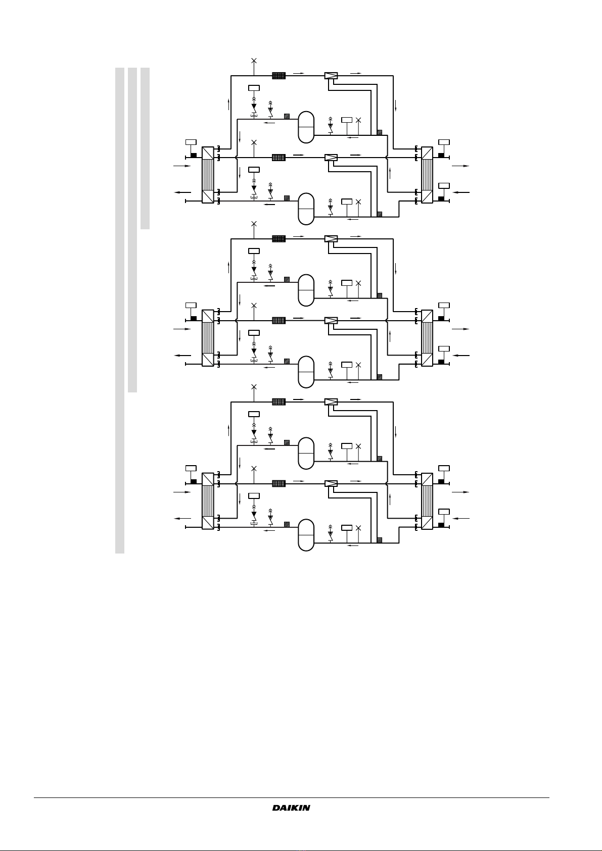
Internal wiring - Parts table
Refer to the internal wiring diagram supplied with the unit. The
abbreviations used are listed below:
A1P........................ PCB terminal unit
A2P.................**.... PCB address card
F1,2,3U...........# .... Main fuses for the unit
F5B,F6B ................ Automatic fuse for the control circuit/secondary
of TR1
F8U........................ Surge-proof fuse
F9U.................## .. Surge-proof fuse
H1P.................* ..... Indication lamp alarm
H3P.................* ..... Indication lamp operation compressor (M1C)
H4P........................ Indication lamp operation compressor (M2C)
K1A........................ auxiliary contactor for alarm (for 16~24Hp only)
K1A........................ auxiliary contactor for high pressure
(for 32~72Hp only)
K1M ....................... Compressor contactor (M1C)
K1P ................ * .....Pumpcontactor
K2M........................Compressor contactor (M2C)
K4S ........................Overcurrent relay (M1C)
K5S ........................Overcurrent relay (M2C)
K19T ......................Timer, time delay for M2C
M1C,M2C...............Compressor motor
PE ..........................Main earth terminal
Q1D........................Discharge thermal protector (M1C)
Q2D........................Discharge thermal protector (M2C)
R1P........................Reverse phase protector
R3T ........................Evaporator inlet water temperature sensor
R4T ........................Evaporator outlet water temperature sensor
(Freeze up sensor)
R5T ........................Condenser inlet temperature sensor
S1HP,S2HP............High pressure switch
S4LP,S5LP.............Low pressure switch
S7S ........................Switch for remote cooling/heating selection
(for 16~24Hp only)
S7S ........................Changeable digital input 1(for 32~72Hp only)
S9S ................ * .....Switch for remote start/stop (for 16~24Hp only)
S9S ................ * .....Changeable digital input 2 (for 32~72Hp only)
S10L............... #.....Flowswitch
S11L............... #.....Contact that closes if the pump is working
S12S .............. #.....Main isolator switch
TR1 ........................Transfo 230 V
➞
24 V for power supply of
controllers
Y1R........................Reversing valve
Y1S ........................Solenoid valve for injection line
X1
...........................Connector for digital inputs, analog inputs, analog
outputs and for power supply controller (A1P)
X2...........................Connector for digital outputs (A1P)
X3...........................Connector for (A1P)
X4,X5,X6................Interconnection connector Main
↔
Control
switchbox
Terminal unit: Digital Inputs
X1 (ID1-GND) ........flowswitch
X1 (ID2-GND) ........remote cooling/heating selection
X1 (ID3-GND) ........high pressure switch + discharge protector +
overcurrent
X1 (ID4-GND) ........low pressure switch
X1 (ID5-GND) ........remote On/Off
Terminal unit: Digital outputs (relays)
X2 (C1/2-NO1).......compressor M1C on
X2 (C1/2-NO2).......compressor M2C on
X2 (C3/4-NO3).......voltage free contact for pump
X2 (C3/4-NO4).......voltage free contact for reversing valve
X2 (C5-NO5)..........alarm voltage free contact
Terminal unit: Analog inputs
X1 (B1-GND)..........evaporator inlet water temperature
X1 (B2-GND)..........evaporator outlet water temperature (Freeze up
sensor)
X1 (B3-GND)..........condenser inlet water temperature
Not included with standard unit
Not possible as option Possible as option
Obligatory # ##
Not obligatory * **