Freightliner M2
COMPANY CO NFIDENTI AL
© 2019 SmartDrive Systems, Inc. This information is intended for use by SmartDrive customers only. Any other use without the express written consent of SmartDrive Systems, Inc. is strictly prohibited. Rev 5, December 11, 2019
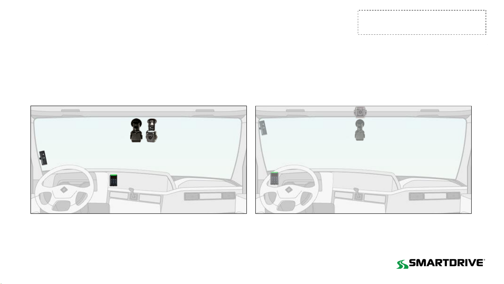
Approved ADAS Forward-facing Camera location
Mounting Location
Mount the ADAS shroud 1" from the top
and center of the windshield
The camera cannot interfere with a driver’s line of sight
of the road, traffic signals, or road signs.
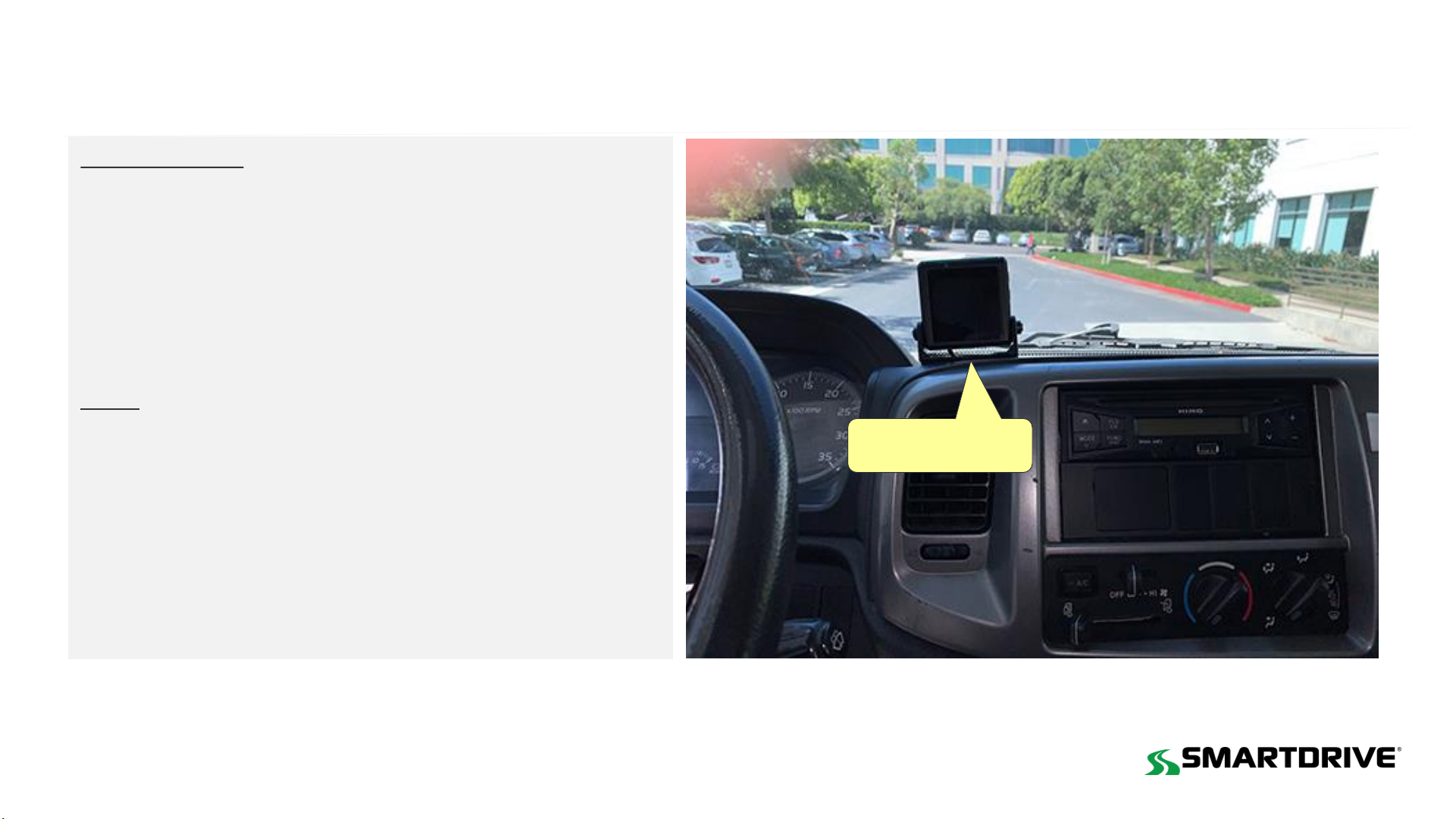
Details
1. Before removing the adhesive backing, check to make sure the camera
fits properly
2. Using an alcohol pad clean the windshield and wipe dry with a lint-free
clean cloth
3. Critical: Use a pocket level to ensure that the bottom of the camera
is mounted level looking from left to right.
4. Press firmly on camera bracket for 10 seconds to ensure adhesion
5. Run camera cable under the headliner towards the driver side
6. Remove the A-pillar cover and run the camera cable down to the
controller. Ensure the cable doesn’t get pinched.
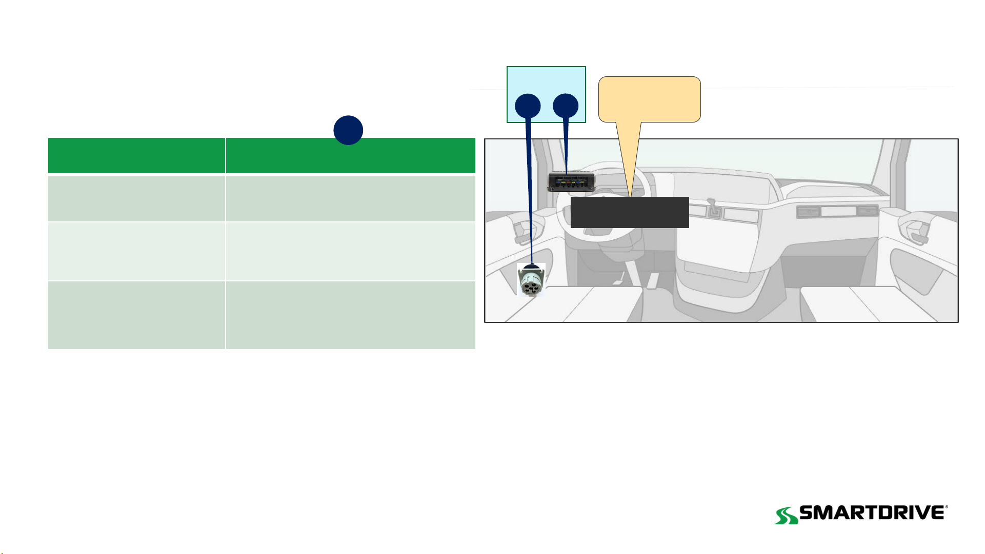
This camera requires calibration.
Details are available in the
ADAS installation and Calibration guide
Camera Location