DAIREN SSW 24-4ND User manual

Operation Manual of 24V UPS
Revision: 01
Date: Dec.5. 2021
Page 1 of 10
Uninterruptible Power Supply (UPS)
EBOPS Vision
Model : SSW 24-4ND

Operation Manual of 24V UPS
Revision: 01
Date: Dec.5. 2021
Page 2 of 10
1) Block Diagram
Standby Mode
UPS consists of a rectifier, a set of batteries, and an inverter. It enables
the batteries to be charged through the rectifier and, at the same time,
provides supply to the load during normal conditions. (Figure 1)
Emergency Mode
The battery will restore its energy in the form of DC currents to the
inverter, and the inverter will supply AC currents to the load when the mains
fails (Figure 2).
When the AC mains resumes, the batteries will be recharged
immediately through the electrical change over contact. The mains will
supply to the loads as shown in (Figure 1).

Operation Manual of 24V UPS
Revision: 01
Date: Dec.5. 2021
Page 3 of 10
2) Wiring connection
The wire connection of AC supplies, load, and battery to the terminal
block are shown as below:
Terminals
Connection
Cable size (sq.mm)
220V_L
Mains line wire
>1.5
220V_N
Mains neutral wire
>1.5
E
Earth wire
>2.5
LS/LT
Loads line wire
>1.5
NS/NT
Loads neutral wire
>1.5
BAT+
Battery positive
>4.0
BAT-
Battery negative
>4.0
P1/P2
DC loads positive
>1.5
N1/N2
DC loads negative
>1.5
Cautions : Ensure power supply at the input MCB and maintenance switch is
switched off before making any connections.
Observe correct polarity of battery terminals. Batteries are
connected in series (24V system)
220VAC
Input
MAX
120W
Load
MAX
120W
Load

Operation Manual of 24V UPS
Revision: 01
Date: Dec.5. 2021
Page 4 of 10
3) Definitions of Control Port Terminals
Volt+,
to TMS02 card
Volt-
AMP+
, AMP-
P75+,
To elevator control system
P75-
T_P
NC( Auxiliary power)
T_S
NC( Auxiliary power)
+5V if emergency operating successes
0V if emergency operating fails
24VDC
Battery
24VDC
Output
24VDC
Output

Operation Manual of 24V UPS
Revision: 01
Date: Dec.5. 2021
Page 5 of 10
4) Battery Temperature Sensor
4.1 Purpose
The battery temperature sensor can detect the temperature of the battery
casing in real time. If the battery temperature exceeds the maximum
threshold during the float charging, the UPS charging voltage will be
reduced to compensate for the temperature increase.
4.2 Installation
It is necessary to tape the metal probe of the battery temperature sensor
onto the side of the battery casing.
4.3 Testing
The metal probe of the battery temperature sensor can be brought close
to the heat source. When the sensor temperature increases, float charging
voltage should be reduced.
Battery
Temperature
Sensor

Operation Manual of 24V UPS
Revision: 01
Date: Dec.5. 2021
Page 6 of 10
5) Timer Setting
Upon clicking the button Timer Switch, the LED panel will display
the voltage and current for 4 hours.
6) Definitions of MCB
The Input MCB is installed on the left side of the door panel and will input
230VAC to the UPS.
The Output MCB is installed on the right side of the door panel and will output
230VAC to the load.

Operation Manual of 24V UPS
Revision: 01
Date: Dec.5. 2021
Page 7 of 10
The battery switch (maintenance switch) is used to isolate the AC supply from
the rectifier and also to cut off the DC supply to the inverter during maintenance.
This battery switch must be turned off when the battery is replacing. Likewise it
is also recommended to turn off all UPS circuit breakers.
7) Use environment
Item
Range
Operating temperature
-10℃~60℃
Ambient humidity
20%~90% (non-condensing)
Storage temperature
-25℃~55℃
Battery
Switch

Operation Manual of 24V UPS
Revision: 01
Date: Dec.5. 2021
Page 8 of 10
8) Start up with AC present
Procedures for start up :
1、Switch on the AC
supply at the AC
distribution panel
2、Switch on the Battery Switch and
the following can be observed :
a) The DC Voltmeter will indicate the
battery terminal voltage.
b) The "MAINS ON" LED indicator
on the panel lights up.
c) The DC Ammeter will reflect to
the battery charge current.
3、Switch the
"OUTPUT ON / OFF"
MCB on the panel to
the position "ON".
4、To ensure the UPS
to operate as per
specification, the
batteries must be
charged for not less
than 24 hours.

Operation Manual of 24V UPS
Revision: 01
Date: Dec.5. 2021
Page 9 of 10
9) Simulation of mains failure
Simulation of mains failure by Switch off input MCB
1、The inverter Red LED
indicator will lights up at
the same time, the mains
Green LED indicator goes
off.
2、The DC Ammeter will
reflect the battery output
discharge current.
3、If required to test the
UPS for longer duration,
the AC supply to the UPS is
advisable to be switched
off.
4、When the batteries
discharged to its critical low
voltage level, the Electronic
Low-Voltage .
Cut Off Circuit will activate.
5、Switch on the AC supply
to the UPS to resume its
normal operation.

Operation Manual of 24V UPS
Revision: 01
Date: Dec.5. 2021
Page 10 of
10
9) Battery Installation and Wiring
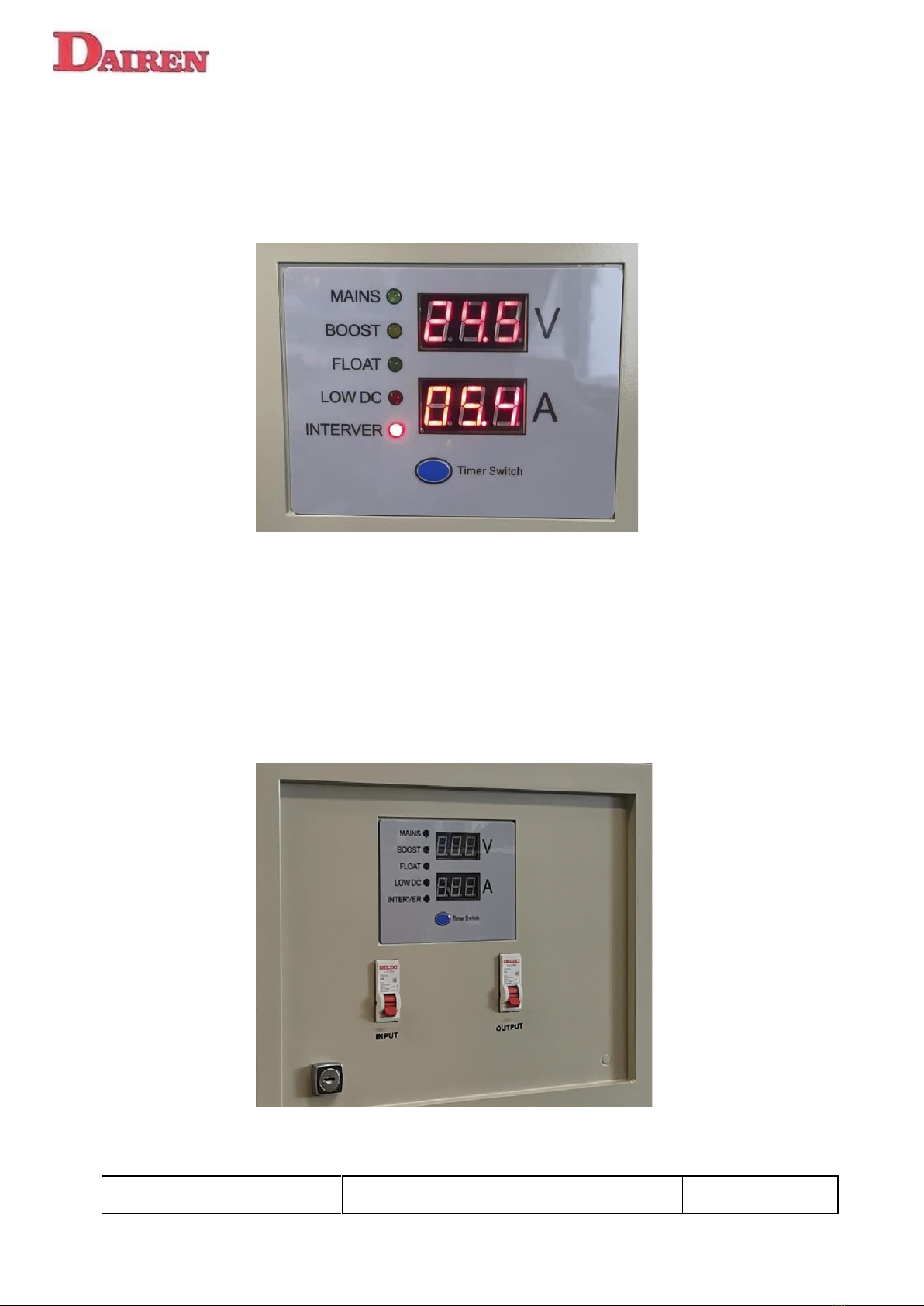
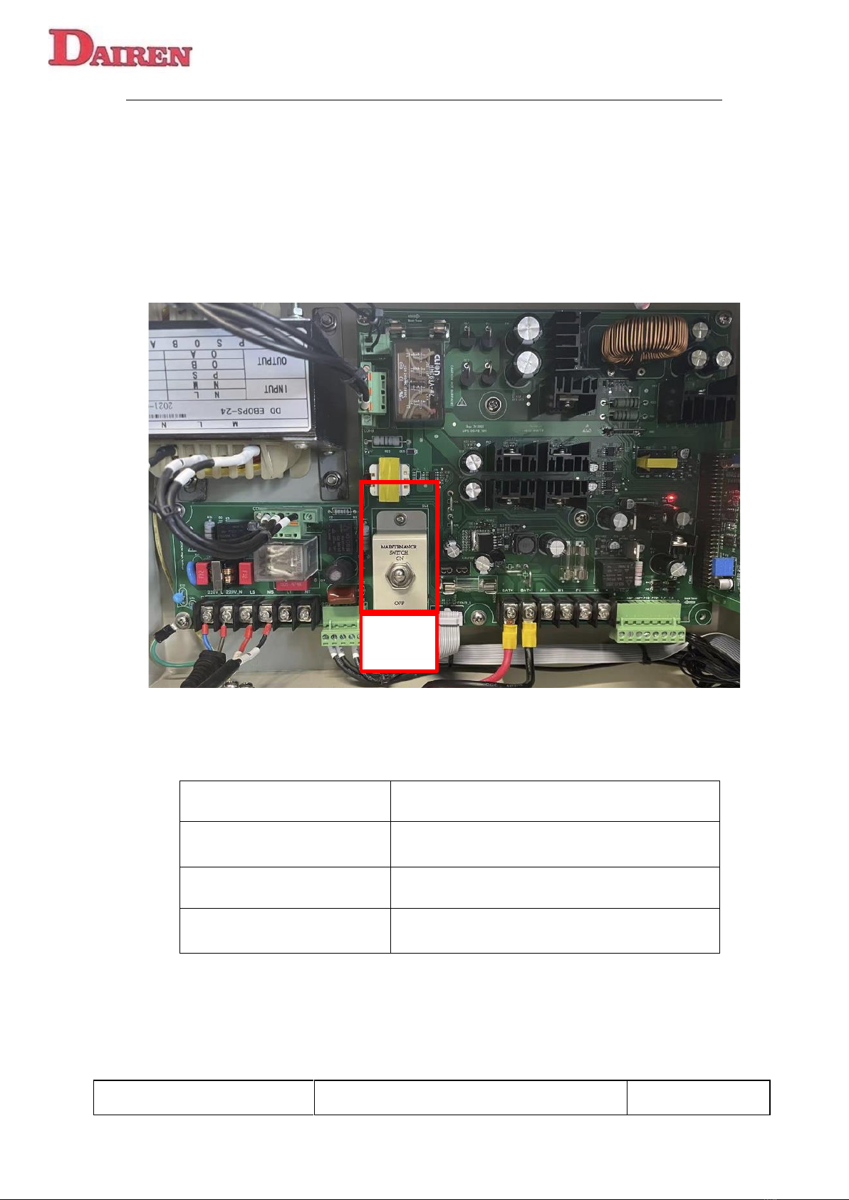
9.1 Ensure the INPUT MCB and OUTPUT MCB on the UPS door panel
and the MAINTENANCE SWITCH on the PCB card must be at off
position .
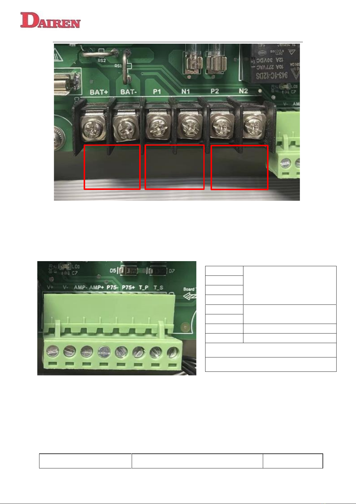
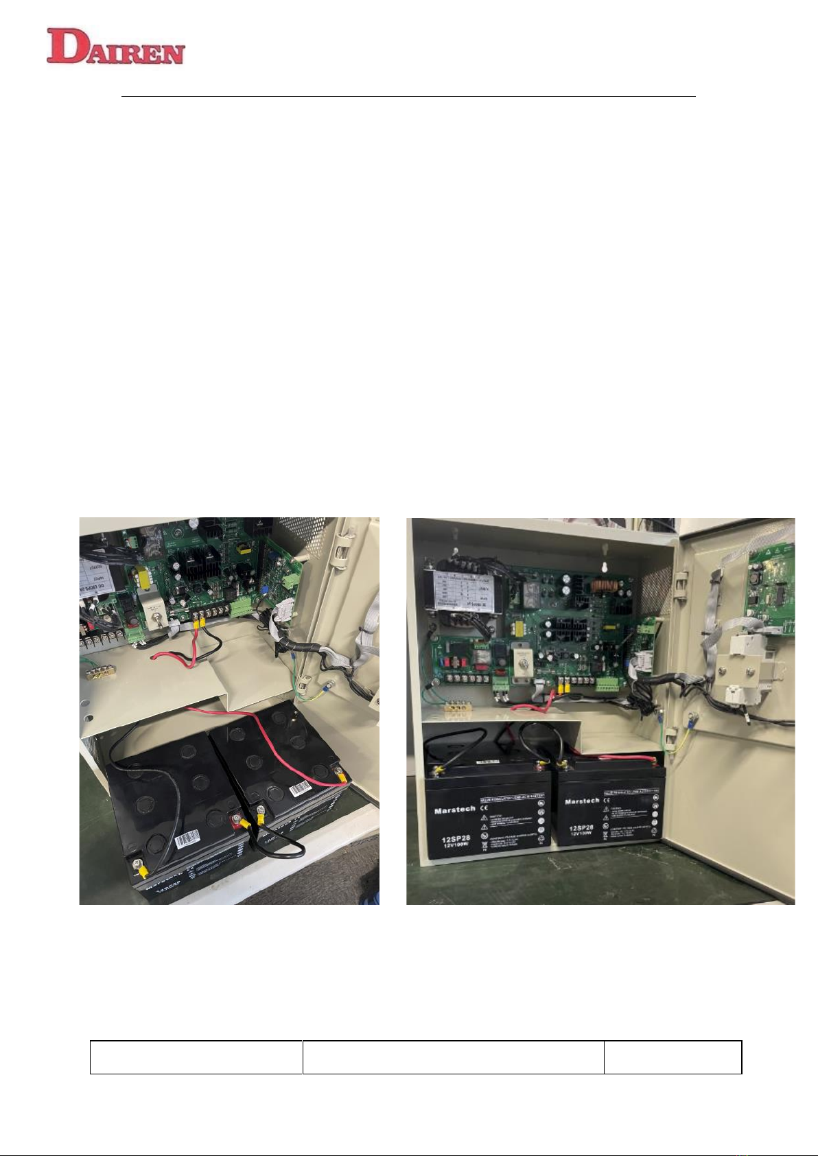
9.2 The positive and negative wires of the battery are installed on the
BATT+ and BATT- of the PCB card respectively.
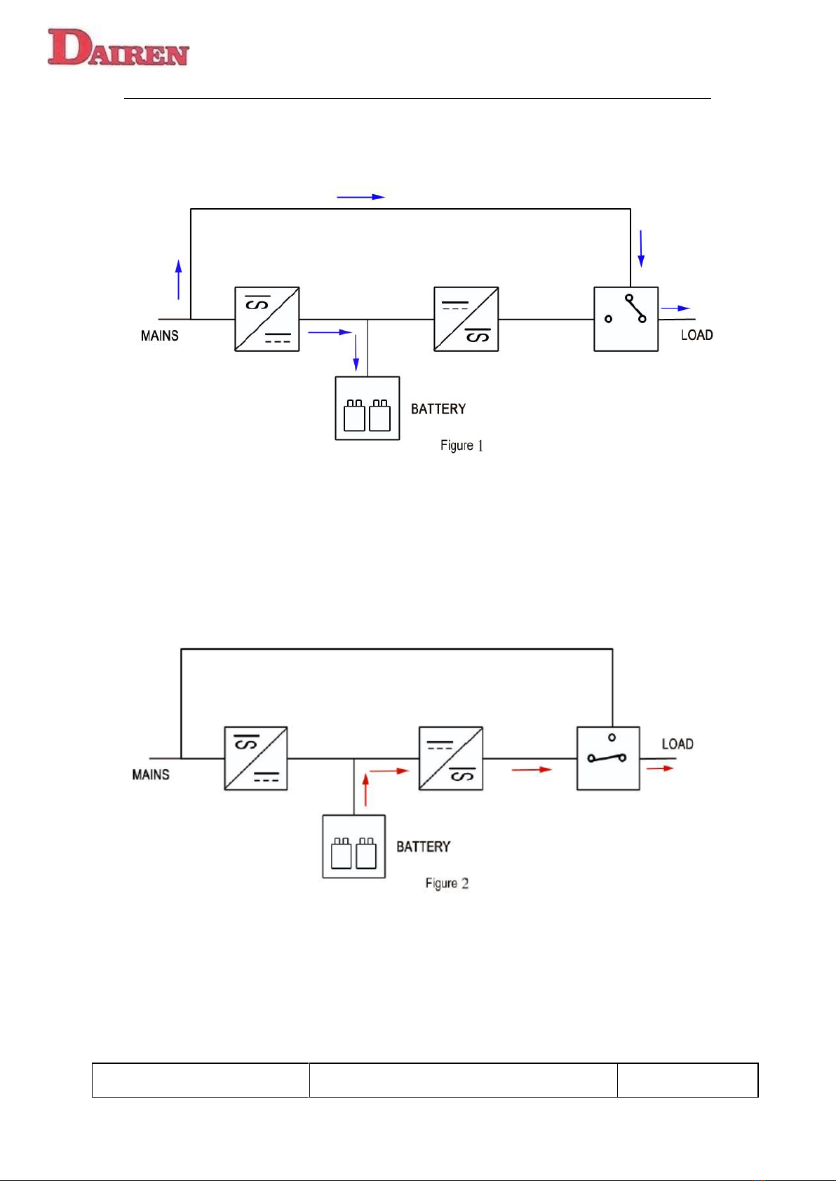
9.3 Connect the battery cables one by one and confirm the positive and
negative polarity of the battery. (Figure 1)
9.4 Arrange the battery cable and push the battery into the cabinet
battery compartment.(Figure 2)
9.5 Battery installation and wiring completed.
Note: Before turning on OUTPUT MCB, must ensure the AC load is not short
circuited or overloaded (more than 120W)
Figure 1 Figure 2
Table of contents
Other DAIREN UPS manuals
Popular UPS manuals by other brands

Eaton
Eaton 93PR Series User and installation guide

Voltronic Power
Voltronic Power Nano 400 quick guide

Intex
Intex KOM0315 user manual

Toshiba
Toshiba 1400XL Plus Series Operation manual

Emerson
Emerson Liebert itON BX quick start guide

Ever Power Systems
Ever Power Systems POWERLINE RT PLUS 1000 instruction manual

Tripp Lite
Tripp Lite AVR750U owner's manual

Tripp Lite
Tripp Lite SmartPro Rackmount SMX500RT1U Features and specifications

Tripp Lite
Tripp Lite SmartPro SMART1000RM2U technical information

Tescom
Tescom ML100EX user manual

Speco
Speco UPS-1000VA Specifications

Liebert
Liebert UPStation GXT700MT-120 user manual