Daisy 1200 User manual
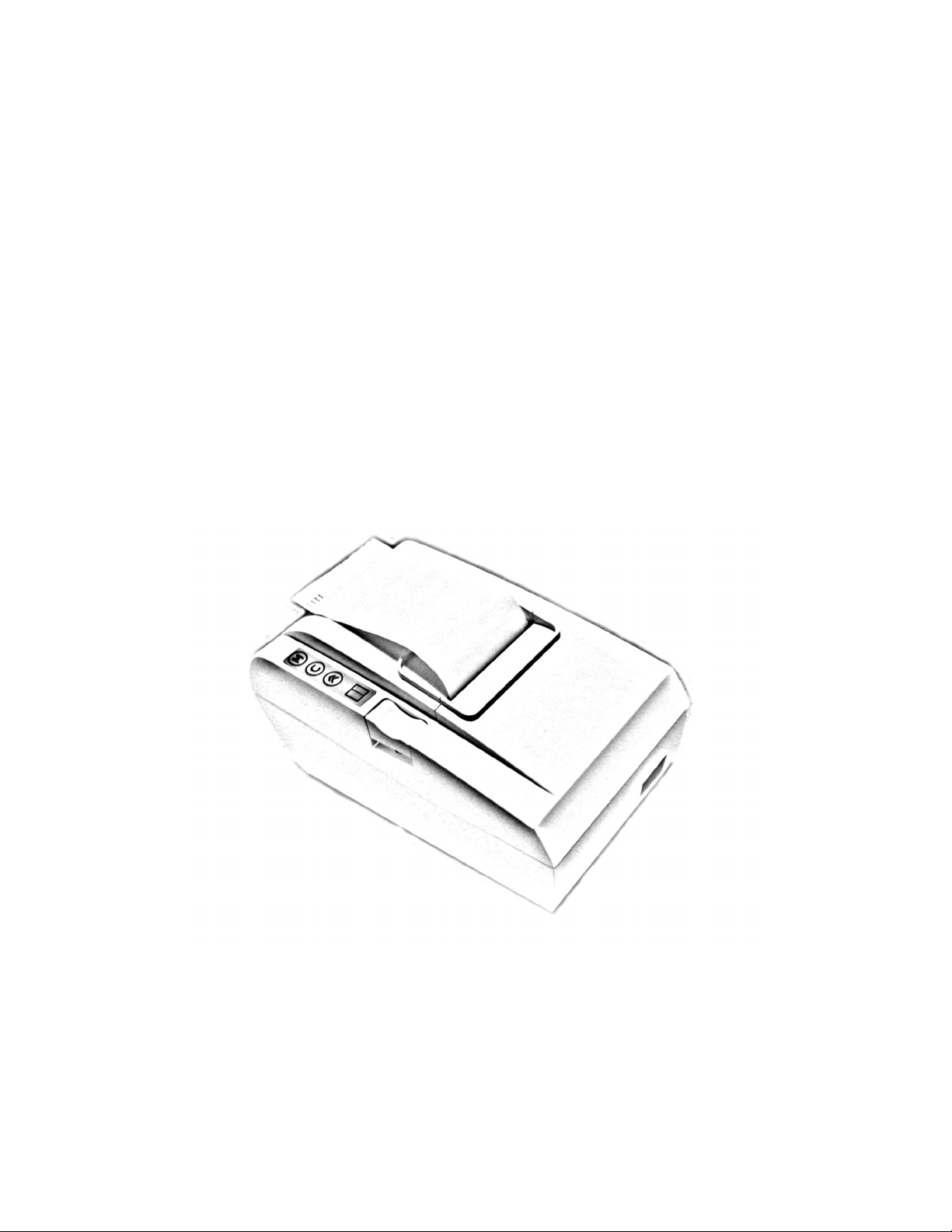
Daisy 1200
ESC/POS PRINTER
User's manual

CONTENTS
1. GENERAL OUTLINE
1.1. eatures
1.2.Unpacking
1.3.Specifications
2. PREPARATION
2.1.Connecting the AC adapter and AC power cord
2.2.Connecting the interface cables
2.3.Loading the paper
3. OPERATION PANNEL
3.1.LED indicators
3.2.Buttons unctions
3.3.Wireless Bluetooth communication
4. COMMAND LIST

1 GENERAL OUTLINE
1.1 Features
The Daisy 1200 Printer is a line thermal printer which can be used in
different applications like communication terminals, ESC POS terminals &
networks, and more.
•ESC POS printer
•Compact design
•Low-noise printing
•Auto cutter mechanism provided as a standard unit
•Built-in input buffer
•Bar code printing
•High-speed printing at 150 mm s max.
•Power supply - AC adapter
•Built-in Drawer Kick-out interface
•Optional Wireless Bluetooth communication feature
1.2 Unpacking
When unpacking the printer, confirm that the following items are provided:
•Printer ............................................................ 1 unit
•AC adapter .................................................... 1 unit
•AC power cord ............................................... 1 piece
•Sample paper roll .......................................... 1 piece
•CD…............................................................... 1 piece
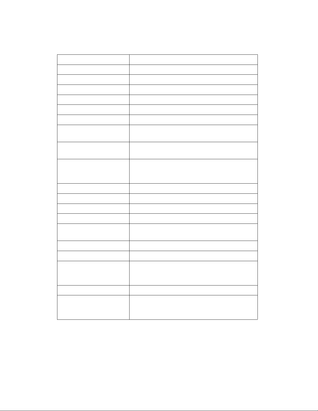
1.3 Specifications
Item Specifications
Print Method Line thermal print method
Printer SEIKO CAP G247A
Print Width 54 mm, 432 dots
Dot Density 8 dots mm (Horizontal Vertical)
Paper Feed Pitch 0.125 mm
Print Speed 100 mm sec, Max 150 mm sec
Number of print
columns
36 (Font A)
43 (Font B)
Character Size Font A: 12x22
Font B: 10x20
Bar Code Types EAN13, EAN8, UPC-A, UPC-E, Codebar,
Interleaved 2 of 5, Code 39, Code 93,
Code 128
Paper Thermal roll: Max W57mm, ø55mm
Paper Thickness 60-65 µm
Interface RS-232C Interface, max 115200 bps
Power Consumption 60W max
Adapter Input: AC 100-240V, 1.0A, 50 60Hz
Output: DC +24V, 2.5A
Weight
External Dimensions
Operating
Temperature
and Humidity
5 ÷ 40 ºC, 30 ÷ 85% RH
Storage Temperature -10 ÷ 60 ºC, 10 ÷ 90% RH
Reliability Print head life: 100 million pulses or 100
km print length.
Auto Cutter life: 1 million cuts.

2 PREPARATION
2.1 Connecting the AC adapter and AC power cord
2.1.1 Switch the printer's power button off.
2.1.2 Insert the power cable connector into the power connector
on the back side of the printer.
2.1.3 Connect the AC power cord to the AC adapter, and insert the
AC-power cord plug into a suitable wall outlet.

2.2 Connecting the interface cables
2.2.1 Turn the printer off.
2.2.2 Insert the RJ connector into the interface connector on the
back panel.
2.2.3 Connect the other end of the interface cable to the host
computer.
If the printer has a Bluetooth module you may not need to
connect the interface cable. Refer to section 3.3 for details.

2.3 Loading the paper
2.3.1 Turn the printer off.
2.3.2 Push the eject button and open the printer cover.
2.3.3 Place the paper roll into the the roll holder as shown on the
picture above.
2.3.4 Push on the printer cover until a “click” is heard.

3 OPERATION PANEL
3.1 LE indicators
•Power LED
The LED is activated when
printer's power is turned
on.
•Mode LED
The LED is activated when
the printer is printing.
On error the LED is blinking
until the error is cleared.
3.2 Buttons functions
•EED
When FEED button is pressed the printer feeds one line of paper.
When the FEED button is held down for 2-3 seconds the printer
feeds the paper continuously.
•CLEAR
When an error occurrs the user needs to press the CLEAR button to
clear the error and to continue printing.
•MODE
There are two modes depending on the other buttons:
SELF-TEST mode.
Turn the printer off. Press simultaneously MODE and FEED buttons.
Turn the printer on. Wait until it beeps three times, then release the
buttons. The printer will print its current configuration.
RESET SETTINGS TO DEFAULTS mode.
Turn the printer off. Press simultaneously MODE, CLEAR and FEED
buttons. Turn the printer on. Wait until it three times, then release the
buttons. The printer will print a message:

“Restore default settings ”
“* press MODE for Yes”
“* press FEED for No”
Press MODE to restore the defaults settings or
FEED to cancel the operation.
3.3 Wireless Bluetooth communication
If your printer has a Bluetooth module installed You will be able to
establish connections to the host computer without communication
cable. To enable the Bluetooth module You have to press and hold
down MODE and CLEAR buttons simultaneously while the printer is
powered (the Power LED is on). The following message will be
printed:
“Bluetooth ON”
Press and hold down MODE and CLEAR buttons simultaneously
once again to disable the Bluetooth module. The following message
will be printed:
“Bluetooth OFF”
NOTE: The Bluetooth module is enabled and disabled by pressing
buttons while the printer is on. For Self-test and Reset settings
modes You have to turn the printer off before pressing and holding
down any button.
NOTE: The Bluetooth module supports the following baud rates:
9600 bps, 19200 bps, 38400 bps, 57600 bps, 115200 bps.
The baud rate is set by the application running on the PC.

4 COMMAND LIST
1HT Horizontal tab command
2L Print and Line feed
3CR This command is ignored
4ESC SP Set character spacing
5ESC $ Set absolute position
6ESC % Select cancel user character set
7ESC & Define user characters
8ESC ! Print mode collective specification
9ESC * Set bit image mode
10 ESC - Set cancel underline mode
11 ESC . Print diagnostic information
12 ESC 2 Set 1 6-inch line spacing
13 ESC 3 Set n 256-inch line spacing
14 ESC = Data input control
15 ESC @ Initialize printer
16 ESC D Set horizontal tab position
17 ESC E Set cancel highlighting
18 ESC G Set cancel double printing
19 ESC J Print and feed paper n 256 inch
20 ESC M Select character font A or B
21 ESC R Set international character set
22 ESC T Print short diagnostic information
23 ESC t Set encoding table
24 ESC X Set maximum print speed
25 ESC Y Set intensity level (1st variant)
26 ESC Z Transmit identification string
27 ESC \ Set relative position
28 ESC a Set text alignment
29 ESC d Print and feed the paper n lines
30 ESC i Cut paper (full cut)
31 ESC m Cut paper (partial cut)
32 ESC p Generate a drawer-kick pulse

33 ESC v Transmit printer’s status
34 ESC s Save configuration to the non-volatile memory
35 GS D n Set intensity level (2nd variant)
36 GS ( A Print a self-test
37 GS L Set left print margin
38 GS V Cut paper
39 GS W Set width of printable area
40 GS k Print barcode
41 GS w Set barcode horizontal size (scale factor)
42 GS h Set barcode height
43 GS H Set HRI code printing position
44 GS f Select HRI code font
45 GS v 0 Print raster bit image
46 GS * Download bit image
47 GS / Print downloaded bit image
48 GS T Turn Bluetooth module on off
49 GS B Set communication speed
1. HT
Horizontal Tab command
[Code] [09h]
[Outline] Shifts the printing position to the next horizontal tab position.
• Ignored when the next horizontal tab position has not been set.
• The horizontal tab position is set by ESC D.
• Initial setting of the horizontal tab position is each 8 characters in
9th, 17th, 25th columns.
[See Also] ESC D
2. L
Print and feed the paper
[Code] [0Ah]
[Outline] Prints data contained in the input buffer.
[See Also] ESC 2, ESC 3
3. CR
Print command
[Code] [0Dh]
This command is ignored.

4. ESC SP n
Set character spacing
[Code] [1Bh] + [20h] + n
[Range] {0 <= n <= 0Fh}
[Outline] The rightward spacing is set in dot units (1 203 inch unit).
[Caution] The rightward spacing is doubled if double width print mode is
enabled.
[Default] n = 0
5. ESC $ n1 n2
Set absolute position
[Code] [1Bh] + [24h] + n1 + n2
[Range] {0 <= n1 <= FFh}
{0 <= n2 <= 2}
{0 <= n1+n2*256 <= 216}
[Outline] The printing start position is specified by the number of dots (1 203
inch unit) from the beginning of line.
The printing start position is equal to n1 + n2 x 256 from the
beginning of line.
[Default] The initial value is not specified.
[See Also] ESC \
6. ESC % n
Select/cancel user character set
[Code] [1Bh] + [25h] + n
Only bit 0 of n is significant
Value 0: Selected
Value 1: Not selected
[See also] ESC &
7. ESC & m n1 n2 [ d ] k
Define user characters
[Code] [1Bh] + [26h] + m + n1 + n2 + D1 + … + D(m-n+1)k
[Range] {m = 0-3 Subcommand}
{20h <=n1 <= FFh }
{n1 <= n2 <= FFh }
{k = (n2-n1+1)*44 when m=2 and k = (n2-n1+1)*40 when m=3 }
[Outline] Defines a group of user characters.
m=0: Copy internal character set A to user character set A
(Parameters n1, n2 and d are omitted)
m=1: Copy internal character set B to user character set B
(Parameters n1, n2 and d are omitted)
m=2: Define character group with ASCII codes between >=n1
and <=n2 for character set A (12x22). Every character is 44 bytes,
two bytes for each line.
m=3: Define character group with ASCII codes between >=n1
and <=n2 for character set B (10x20). Every character is 40 bytes
long.

n1 is the ASCII code of the first and n2 is the ASCII code of the
last of (n2-n1+1) consecutive symbols.
To define a single symbol choose n1=n2.
d is the data that defines the symbols. Every Font A symbol
consists of 44 bytes while every Font B symbol consists of 40
bytes.
Every font symbol is defined left to right, top to bottom, two bytes
for each horizontal line. Every bit denotes one dot. A bit set to ‘1’
means black dot. The most significant bit is the starting one.
[See Also] ESC %
8. ESC ! n
Print mode collective specification
[Code] [1Bh] + [21h] + n
[Range] {0 <= n <= FFh}
[Outline] Each n bit sets a print modifier according to the table:
Bit unction Value “0” Value “1”
0 Character Font Font A Font B
1 Quadruple Height Canceled Set
2 Quadruple Width Canceled Set
3 Condensed Canceled Set
4 Double Height Canceled Set
5 Double Width Canceled Set
6 Not Used
7 Underlined Canceled Set
[Default] n = 0
[See Also] ESC E, ESC –
9. ESC * m n1 n2 [ d ] k
Set bit image mode
[Code] [1Bh] + [2Ah] + m + n1 + n2 + D1+ … + Dk
[Range] {m= 0, 1, 32, 33 bit image mode (See the table below.)}
{0 <= n1 <= FFh}
{0 <= n2 <= 3}
{0 <=d <=FFh)
{k = n1 + 256 x n2 (m = 0, 1)
{k = (n1+256 x n2) x 3} (m = 32, 33)
[Outline] Prints a graphic line.
According to the number of dots specified by n1, n2, specify the bit
image of mode m.
• The total number of dots printed in the bit image is equal to n1 +
(256 x n2).
• When bit image data has been sent in excess of dot position of
one line (432 dots), the excess data is discarded.
• d is bit image data, the bits subject to printing are set (“1”) and

those not – cleared (“0”).
• The bit image modes specified by m are as follows:
Vertical Direction Horizontal Direction
m Mode Dots Dot Density Dot Sensity Max. Dots
08-dot single density 8 67 dpi 101 dpi 216
18-dot double density 8 67 dpi 203 dpi 432
32 24-dot single density 24 203 dpi 101 dpi 216
33 24-dot double
density
24 203 dpi 203 dpi 432
[Caution] • When the value of m (bit image mode) is out of the above range,
the data following after n1 is processed as normal printing data.
• After completion of a bit image printing, the printer returns to
normal data processing mode.
The command has another variant with four new modes:
ESC * m n[ d ] k
ESC * m n a f [ d ] k
Specifying the Bit Image Mode (Sending graphics data horizontally)
[Code] [1Bh] + [2Ah] + m + n + { a + [00h] } +D1 + … +Dk
[Range] {m = 16, 17, 18, 20 bit image mode}
{0 <= n <= 40h}
{0 <= d <= FFh}
{k = n * 24 * 48} (m = 16)
{k = n * 24 * 48} (m = 17) {After decompression}
{k = n * h * 48} (m = 18) {After decompression}
{k = n * 24 * 48} (m = 20) {After decompression}
{0 <= a <= 24 (Used only for mode 18.)}
{f = 0 (Used only for mode 18.)}
[Outline] In these graphics modes is sent a graphics block with variable
width n*8 dots and height 24 dots for modes 16,17 and a dots for
mode 18. In mode 17 data is compressed, and the bytes count
specified is before the compression. In mode 16 the same data is
without compression. Mode 20 is similar to mode 17, but every
byte is mirrored before putting in the print buffer (bits 0 and 7, 1
and 6, 2 and 5, 3 and 4 change places). All modes are high
resolution (203 x 203 DPI).
• When bit image data have been input in excess of dot position of
one line (432 dots) , the excess data are discarded.
• d is bit image data, the bits subject to printing are taken as “1”
and those not as “0”.
[Caution] • When the values set in m (bit image mode) are out of the above
range, the data following after n is processed as normal printing
data.
• After completion of bit image printing, printer returns to normal
data processing mode.

[Compression procedure for mode 17 and 18]
A simple RLE encoding like this in PCX files is used. If two most
significant bits of the byte are set, the 6 LSB contain a repeat counter
(1-63), and the next byte contains the data to be repeated. A single
data byte with 2 MSB set must be sent as two bytes.
10. ESC – n
Set/cancel underline mode
[Code] [1Bh] + [2Dh] + n
[Range] {0 <= n <= 2}
[Outline] Set cancel underline mode.
• Types of underlines by n value are shown below:
0 Cancel underline.
1 1-dot width underline.
2 2-dot width underline
[See Also] ESC !
11. ESC .
Self-test
[Code] [1Bh] + [2Eh]
[Outline] Prints the character table, character samples with different
attributes and diagnostic information.
[See also] ESC ,
12. ESC 2
Set 1/6-inch line spacing
[Code] [1Bh] + [32h]
[Outline] The line spacing is specified in units of 1 6 inch.
13. ESC 3 n
Set n/256-inch line feed spacing
[Code] [1Bh] + [33h] + n
[Range] {0 <= n <= FFh}
[Outline] The line spacing is specified in units of 1 203 inch.
[Default] The initial value is n = 34 (1 6 inch) (22h), being 4.23 mm line
spacing.
14. ESC = n
Data Input Control
[Code] [1Bh] + [3D] + n
[Range] {0 <= n <= FFh}
[Outline] Only bit 0 is significant:
Value 0: Selected
Value 1: Not selected
When the printer is not selected, it ignores all the received data
until it is selected by this command.
[Caution] • Even when the printer has not been selected, it can enter BUSY
state through printer operation.
[Default] • The initial value of n is “1”.

15. ESC @
Reset printer
[Code] [1Bh] + [40h]
[Outline] Clears data stored in the print buffer and resets the following
settings to their default values:
•remove all attributes from the printing mode;
•set the character spacing to 0;
•turn off the inverse mode;
•set the absolute position to 0;
•deselects User Font.
[See also] ESC ^ and ESC _
16. ESC D [ n ] k NUL
Set Horizontal Tab position
[Code] [1Bh] + [44h] + n1 + … + nk + [00h]
[Range] {0 <= n <= 18h}
{0 <= k <= 20h}.
[Outline] Sets a horizontal tab position.
• “n” indicates the number of columns from the beginning to the
horizontal tab position. For example, to set the position at 9-th
column, n=8 is to be specified. The maximum value allowed to be
set is 24.
• “k“ denotes the number of horizontal tab positions you want to
set. At most 32 tab positions can be set.
• <n> k denotes a list of setting positions in ascending order,
terminated with <00h>.
• ESC D NUL clears all tab positions previously set.
[Caution] When nk is equal to or smaller than nk-1, it is assumed that tab
setting is finished. If this is the case, the next data onward will be
processed as normal data.
[Default] • Initial value is specified for each eight characters(9th, 17th, 25th
column).
[See Also] HT
17. ESC E n
Set/cancel character highlighting
[Code] [1Bh] + [45h] + n
[Range] {0 <= n <= FFh}
[Outline] Set cancel the highlighting characters.
Only bit 0 of n is significant:
0 Cancel highligh mode.
1 Set highlight mode.
[Caution] The print result of double printing and highlighted character
printing is completely the same.
[See Also] ESC !

18. ESC G n
Set/cancel Double Printing
[Code] [1Bh] + [47h] + n
[Range] {0 <= n <= FFh}
[Outline] Set cancel double printing mode.
Only bit 0 of n is valid:
0 Cancel double printing.
1 Specify double printing.
[Caution] The print result of double printing and highlighted character
printing is completely the same.
[See Also] ESC E
19. ESC J n
Print and feed paper n/203 inch
[Code] [1Bh] + [4Ah] + n
[Range] {0 <= n <= FFh}
[Outline] Prints data contained in the print buffer and feeds paper by n 203
inches. Since the actual mechanical pitch is 1 203 inch, it is
internally converted approximately to the value specified with this
command.
20. ESC M n
Select character ont A or B
[Code] [1Bh] + [4Dh] + n
[Range] {0 <= n <= FFh}
[Outline] Selects character font.
Only bit 0 of n is significant:
0 Selects font A (12x22).
1 Selects font B (10x20).
[See also] ESC !
21. ESC R n
Select international character set
[Code] [1Bh] + [52h] + n
[Range] {0 <= n <= 10}
[Outline] Depending on the value of „n“, one of the following character sets
is selected:

22. ESC T
Print short diagnostic information
[Code] [1Bh] + [54h]
[Outline] Prints short diagnostic information.
[See also] ESC .
23. ESC t n
Set encoding table
[Code] [1Bh] + [74h] + n
[Outline] Sets text encoding table
n Text Encoding
0 CP1250
1 CP1251
2 CP1252
3 CP1253
4 DOS866
5 Daisy fiscal printers
24. ESC X n
Set maximum printing speed
[Code] [1Bh] + [58h] + n
[Range] {0 <= n <= 9}
{‘0’ <= n <= ‘9’}

[Outline] Selects the maximum printing speed according to the value of ‘n’:
0 or ‘0’ about 100 mm s
1 or ‘1’ about 90 mm s
2 or ‘2’ about 85 mm s
3 or ‘3’ about 75 mm s
4 or ‘4’ about 70 mm s
5 or ‘5’ about 65 mm s
6 or ‘6’ about 60 mm s
7 or ‘7’ about 55 mm s
8 or ‘8’ about 50 mm s
9 or ‘9’ about 45 mm s
These values are approximate. The real maximum speed depends
on the print intensity and the printing head’s temperature.
[Default] The default value is 0 – maximum printing speed.
25. ESC Y n
Select the intensity level
[Code] [1Bh] + [59h] + n
[Range] {0 <= n <= 2}
[Outline] Set the intensity level.
0 or ‘0’ Set low intensity;
1 or ‘1’ Set middle intensity;
2 or ‘2’ Set high intensity.
[Caution] Higher intensities lead to lower speed. There is another variant of
this command (see GS commands).
[Default] The initial value of n is 1.
[See also] GS D
26. ESC Z
Transmit identification string.
[Code] [1Bh] + [5Ah]
[Outline] The printer transmits 32 bytes of information with the following
structure:
1 – 22: Printer name complemented(padded) with ‘space’ up to 22
symbols.
23 – 25: Firmware version – 3 digits (in ASCII format).
26 – 27: Language version – 2 letters.
28 – 32: 5 bytes flags. Each bit describes a printer feature, as ‘1’
means that the feature is present, while ‘0’ means its absence. Bits
are described as follows:
Bits Meaning:
28.0 Supports IrDA mode
28.1 Supports magnetic stripe card reader
28.2 Supports simultaneous reading of three tracks from a
magnetic stripe card
28.3 ASCII codes above 127 contain Katakana symbols
28.4 Supports JIS and Shift-JIS symbols
28.5 Printer supports ESC . and ESC T commands
28.6 Not Used
28.7 Reserved – always 1
29.0 Supports downloadable fonts and firmware

29.1 Korean support
29.2 Black mark support
29.3 Bar code reader support
29.4 USB A installed
29.5 USB B installed
29.6 Not Used
29.7 Reserved – always 1
Bytes 30, 31 and 32 are always 0x80
27. ESC \ n1 n2
Set Relative Position
[Code] [1Bh] + [5Ch] + n1 + n2
[Range] {0 <= n1 <= FFh}
{0 <= n2 <= FFh}
[Outline] The printing start position is defined as the number of dots (1 203
inch unit) from the current position. Rightward direction is taken as
plus and leftward direction as minus. To specify N dot in minus
(left) direction, use a complement of N for assignment (– N dots =
65536 – N). The number of dots is divided by 256, whose quotient
is taken as n2 and the residual as n1.
[Caution] If the resulting relative position is out of the printable area the
command will be ignored.
[Default] The initial value is not specified.
[See Also] ESC $
28. ESC a n
Aligning the characters
[Code] [1Bh] + [61h] + n
[Range] {0 <= n <= 2}
[Outline] This command is extended and has the following format:
0 or ‘0’ Text is left aligned;
1 or ‘1’ Text is centered;
2 or ‘2’ Text is right aligned.
[Default] The initial value of n is 0.
29. ESC d n
Print and feed the paper by n lines
[Code] [1Bh] + [64h] + n
[Range] {0 <= n <= FFh}
[Outline] Prints data from the print buffer and feeds paper by n lines.
[Default] The initial value is not defined.
30. ESC i
Cut the paper (full cut)
[Code] [1Bh] + [69h]
[Outline] The command performs a full cut.
The command is valid only at the beginning of a line.
Table of contents
Other Daisy Printer manuals