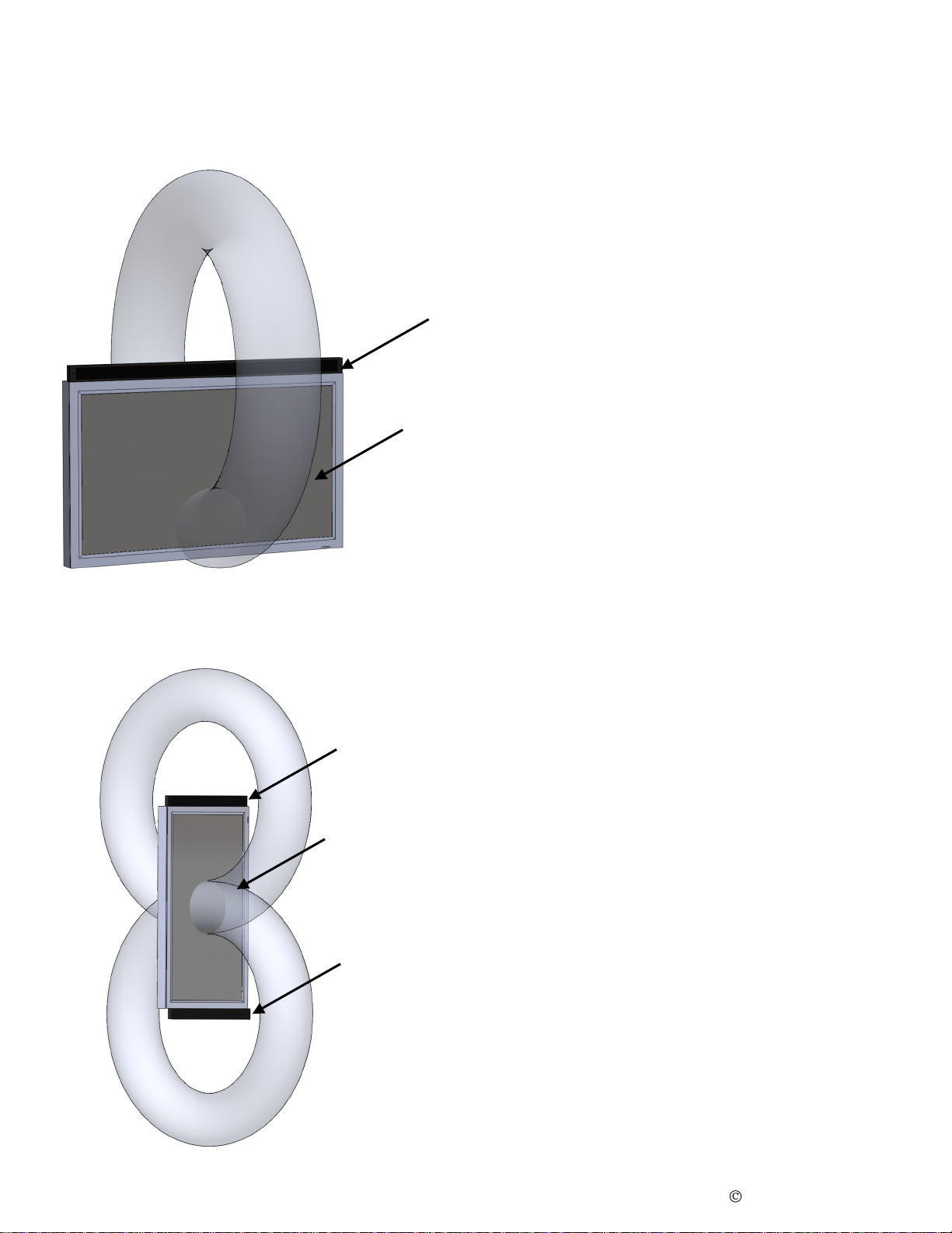
DAKOTA AUDIO MA-5 User manual

DAKOTA AUDIO INC.
MINI-ARRAYS
MA-5 & MA-4
DAKOTA AUDIO INC.
1815 MICHIGAN AVE.
BISMARCK, ND, 58504 USA
PHONE: 701-224-9331
FAX: 701-223-1296
WWW.DAKOTAAUDIO.COM
2011 Dakota Audio Inc.Page 1

SOUND PATTERN
This shows the area of maximum sound level.
The sound extends 360 degrees around the axis of the speaker array.
It gives good sound isolation side-to-side, with very little directionality vertically.
A child in a wheelchair or a pro basketball player will be in the pattern vertically.
It is almost never necessary to “tip” the arrays up or down, there is no directionality up or down.
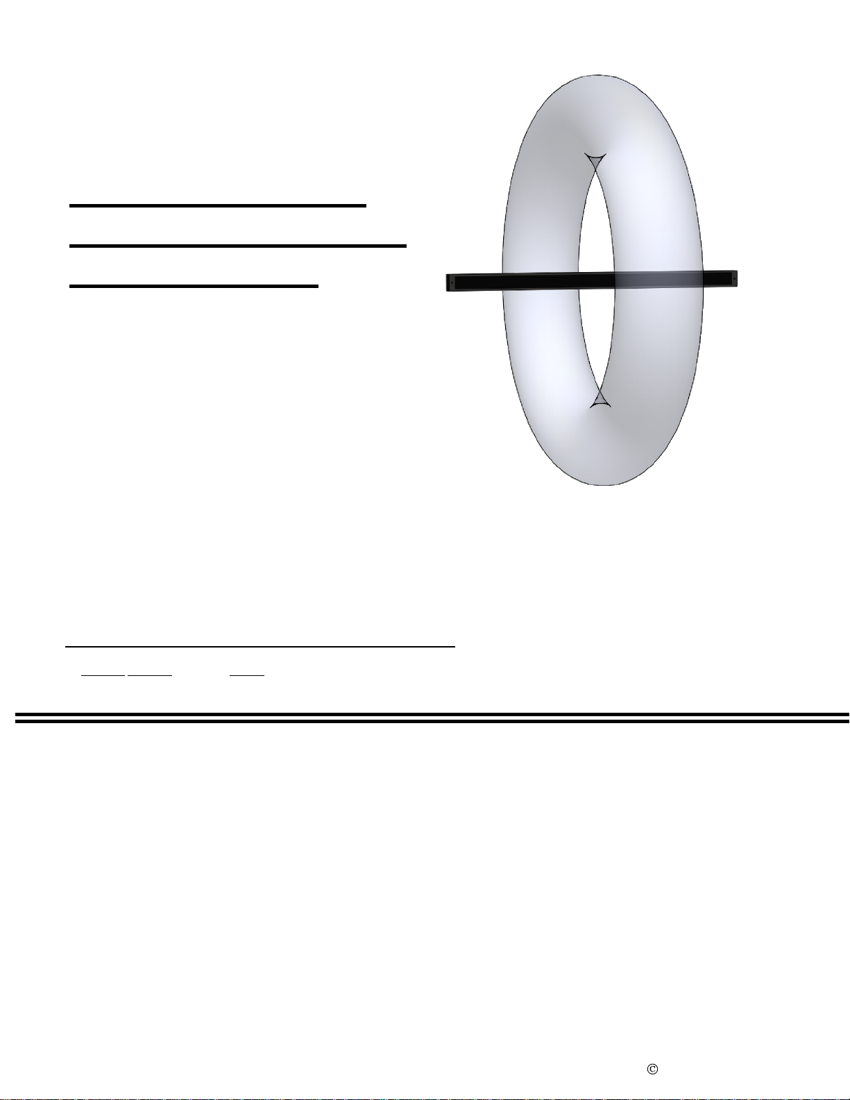
It is not meant to represent all of the sound emitted from the array
. There will be sound outside of the indicated area, but it will be
at a lower level than the sound in the focal area. It is important to note that our ears are logarithmic. In order to achieve a ¾ reduction
in apparent loudness, the sound energy has to be reduced approximately 99%. In quiet areas with reflective surfaces, this can be difficult to achieve.
If you have any questions, please read our white papers that explain this in more detail.
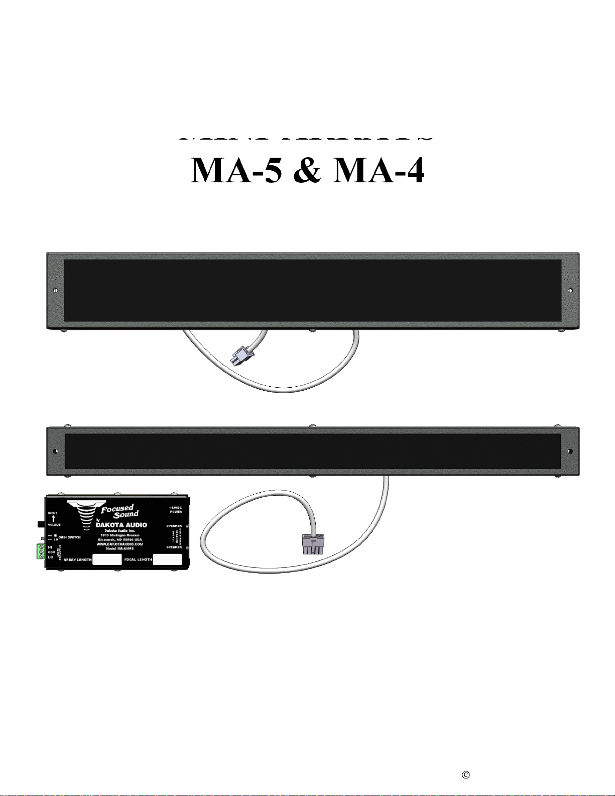
MA-4 OR MA-5
WHICH IS BETTER FOR MY APPLICATION?
MA-4 MA-5
The MA-4 was originally designed for science
museums to have good intelligibility in a noisy
environment. It is smaller than the MA-5.
The low frequency response is limited, it is
designed for voice, not optimal for music.
They come in various lengths, the lengths are
for looks, to match a screen or kisok dimensions.
All the lengths have the same pattern
The MA-5 was originally designed for digital
Signage as in malls, for voice and for incidental
music. The frequency response is tailored for
good voice intelligibility with acceptable low
frequency response.
They come in various lengths, the lengths are
for looks, to match a screen or kiosk dimensions.
All the lengths have the same pattern.
THIS SHOWS THE
AREA OF MAXIMUM
SOUND LEVEL.
IT IS NOT MEANT TO
REPRESENTALL OF THE
SOUND EMITTED BY THE
ARRAY.
2011 Dakota Audio Inc.
Page 2

SPEAKER
SPEAKER
MONITOR IN
PORTRAIT
MODE
SPEAKER
MONITOR IN
LANDSCAPE
MODE
SPEAKER ARRAY MOUNTING
LANDSCAPE MONITOR
In most cases, the speaker array will be mounted
at the top of the video monitor.
Please note that the sound projects from the back
of the array almost as loud as from the front. If
this is a problem it may be necessary to place a
baffle behind the speaker array.
(SEE INFORMATION ON NEXT PAGE)
PORTRAIT MONITOR
A large monitor mounted in portrait mode may
require two speaker arrays to provide satisfactory
vertical coverage. The included amplifier has
two speaker outputs to drive two arrays.
Please note that the sound projects from the back
of the array almost as loud as from the front. If
this is a problem it may be necessary to place a
baffle behind the speaker array.
(SEE INFORMATION ON NEXT PAGE)
2011 Dakota Audio Inc.
Page 3

SPEAKER
SPEAKER
SUGGESTED MOUNTING METHODS
DESK
By mounting the speaker at the bottom of
the monitor, the monitor and the surface of
the desk help reduce the sound spill to the
rear.
SPEAKER
WORK STATION
For increased isolation, especially where
the workstations are mounted back to
back, a physical barrier is recommended
to prevent interference between the
workstations.
FREE STANDING
The sound spill to the rear of a free
standing exhibit can be reduced by
adding a sign or other flat surface above
the speaker array.
ADDED SIGN
(SOUND BAFFLE)
2011 Dakota Audio Inc.
Page 4

PRIVACY BOOTH
PERFORATED METAL
OR FABRIC
FIBERGLASS
OR TECTUM
SPEAKER
ARRAY
SOUND ABSORBING MATERIAL
TYPICAL OF
BOTH SIDES
As it becomes more common to enter private information into a computer, privacy is
becoming an issue.
By combining our mini-arrays with sound absorbing material, privacy can be enhanced
considerably.
With the addition of background noise masking, very good sound isolation can be achieved.
2011 Dakota Audio Inc.
Page 5

3.5mm (1/8”) mini-phone jack input.
Automatically combines stereo to mono.
This input is unbalanced and is
susceptible to noise and hum pickup.
Volume control
This controls the 3.5mm input jack. It
does not have any effect on the
balanced input
Gain switch
Always try the ‘HI” setting first. It’s
better to increase the signal level from
the audio source if possible to reduce the
possibility of noise or hum.
Balanced input
This input is balanced, transformer
isolated. It is generally used with
professional equipment or if the sound
source is located some distance from the
amplifier.
Power jack
12 volt, 0.5 amp power. The power
supply must be regulated, low noise.
The jack is 5.5 / 2.1 mm
Center pin is positive.
Speaker outputs.
The amplifier can drive two speaker
arrays, use either output.
NOTE.
The cables from the speakers should
not be extended. Please contact us for
information.
ALWAYS CONTACT US BEFORE ATTEMPTING TO EXTEND
THE CABLES FROM THE SPEAKER HOUSING TO THE AMPLIFIER.
IF YOU HAVE HUM OR NOISE, GIVE US A CALL,
WE PROBABLY HAVE A SOLUTION.
AMPLIFIER
2011 Dakota Audio Inc.
Page 6

MOUNTING
2011 Dakota Audio Inc.
Page 7
MA-4 MOUNTING WITH INCLUDED SCREWS AND CAPS
DETAIL A
SCALE 2 : 3
# 8 x 1.5" SCREW
DETAIL B
SCALE 2 : 3
PLASTIC CAP
SNAP CAP ONTO
SCREWHEAD
B
A
MA-4 & MA-5 WITH USER SUPPLIED MOUNTING SCREWS
AB
HEAD
PAN
.
.
DETAIL B
SCALE 1 : 1
WASHER
PLASTIC
CAP
DETAIL A
SCALE 1 : 1
FLAT HEAD SCREW
USER SUPPLIEDUSER SUPPLIED
PAN HEAD SCREW
FLAT
HEAD

1.06 5.94
6.28
3.063.25
A B C D
18" 17.11 16.4 8.18
22" 21.26 20.5 10.25
23" 22.26 21.5 10.75
25" 24.16 23.4 11.71
30" 29.16 28.4 14.21
36" 17.21 34.4 35.07
38" 37.16 36.4 18.21
D1.0
.187
A
B
1.52.0
C
2.19
A
3.143.33
C
B
2.54
.187
A B C D
22" 21.50 20.5 10.44
23" 22.25 21.5 10.94
25" 24.25 23.5 11.94
30" 29.25 28.5 14.44
36" 35.25 34.5 17.44
38" 37.25 36.5 18.44
D
2.0
THESE DIMENSIONS ARE SUBJECT TO CHANGE
MA-5 DIMENSIONS
MA-4 DIMENSIONS
AMPLIFIER DIMENSIONS
DIMENSIONS
2011 Dakota Audio Inc.
Page 8
We need to give credit to Mr. William Lobb who, while employed at Jaffe Holden Acoustics, co-
invented this technology.
Some of the ideas presented here the result of conversations with Bill over the years.
This manual suits for next models
1
Table of contents