Dakota Digital COMMANDER Series User manual

CMDX
COMMANDER SERIES REMOTE CONTROL ENTRY SYSTEM
MAN# 650026-A

Switch Position Output function
1 ON 1A momentary 1B latching
OFF 1A and 1B are toggling momentary
2 ON 2A momentary 2B latching
OFF 2A and 2B are toggling momentary
3 ON 3A momentary 3B latching
OFF 3A and 3B are toggling momentary
4 ON 4A momentary 4B latching
OFF 4A and 4B are toggling momentary
5 ON 5A momentary 5B latching
OFF 5A and 5B are toggling momentary
6 ON 6A momentary 6B latching
OFF 6A and 6B are toggling momentary
Terminal Connection
GND chassis ground
PWR to constant +12V power
IGN to key on +12V power
1A grounding(-) output to relay
coil
1B grounding(-) output to relay
coil
2A grounding(-) output to relay
coil
2B grounding(-) output to relay
coil
3A grounding(-) output to relay
coil
3B grounding(-) output to relay
coil
4A grounding(-) output to relay
coil
4B grounding(-) output to relay
coil
5A grounding(-) output to relay
coil
5B grounding(-) output to relay
coil
6A grounding(-) output to relay
coil
6B grounding(-) output to relay
coil
2

3
INTRODUCTION
Thank you for purchasing the CMDX Commander from Dakota Digital. This, along with
many other products that Dakota Digital has to offer, represent the latest in electronics
technology for your street rod, classic car, truck, or custom vehicle.
The CMDX package includes:
•Receiver/controller
•2 key chain style transmitters
•2 dual relay packs
•2 single relay packs
The CMDX can control nearly any configuration of auxiliary outputs through use of the
provided external relays. The CMDX has a total of twelve outputs that can be programmed for a
momentary-on or latch-on and latch-off. Common applications include: power windows, electric
door locks, power trunk, electric tonneau covers, tilt front ends, moon roof control, and other lights
or motors.
A safety feature partially disables the system when the ignition is on to avoid the accidental
opening of a door, or some other undesired function, during vehicle operation. With the ignition
on, the only functions that are allowed to work are outputs 1A, 1B, 2A, and 2B. The ignition will
disable all other outputs, and keep latched outputs at their current state, on or off.
ADDITIONAL TRANSMITTERS
The transmitters supplied with your remote system have a unique serial number coded into
each one for security. Each unit can “learn” up to 7 transmitters. Lost or stolen transmitters are
easily erased by simply reprogramming the remaining transmitters into the system again.
Transmitters from other manufacturers, such as car alarm systems, will not work with the CMDX.
RADIO FREQUENCY INTERFERENCE STATEMENT
FCC IDENTIFIER: KNF6TX
This device complies with part 15 of FCC rules. Operation is subject to the following
two conditions: (1) This device may not cause harmful interference, and (2) This device must
accept any interference received, including interference that may cause undesired operation.

INSTALLATION
The receiver should be mounted in the interior of the vehicle so that it is not exposed to
moisture. It can be secured using the two mounting holes or with a double sided adhesive
tape, such as Velcro. Power, ground, ignition, and all outputs are connected to the push-and-
lock terminal strip along the front edge of the controller. The antenna plugs into the 3 pin
connector, next to the terminal strip. The antenna should be mounted away from any power
wires or motors higher up in the vehicle.
The connections to the main terminal strip are listed on Page 1. The unit only needs
power and ground connected to operate. The others should be hooked up according to your
application. The IGN terminal can be connect to a key on +12V source to disable outputs 3-6
to prevent accidental function while the key is on. The CMDX should only be connected to a 12
volt battery for power and never solely to a battery charger.
All outputs are grounding, or negative, outputs designed to ONLY turn on external relays.
NEVER DIRECTLY CONNECT A CMDX OUTPUT TO A MOTOR, SOLENOID, LIGHTS, OR
SIMILAR LOAD, INTERNAL CIRCUIT DAMAGE WILL RESULT. Figure 1 shows how to wire
ground switched relays to outputs 1A – 6B shown on the first page. Single and dual relay
packs can be used for the CMDX outputs. Additional relay packs are available separately from
Dakota Digital.
FIGURE 1 Wiring a high current relay (ground switched).
If wiring through the door jambs, consider DAKOTA DIGITAL MAGNUM SHOOTERS
to eliminate having any wires running through your door jams. Refer to the following diagrams
for connection to your particular actuators and power windows.
Wiring through door jamb Using MAGNUM SHOOTERS!
4

The following pages of the manual show some common applications and how to wire relays to
the CMDX outputs. These are only suggestions and other relay configurations are possible
depending on your application or device to be driven.
DOOR AND TRUNK LATCH WIRING.
Latches and latch actuators are not included in the kit. These are available separately. If door
motors or solenoids are already mounted in the vehicle, the CMDX system can be used to
control them. All outputs need to be wired through an external relay. Latch motors and
actuators also need to be connected to a momentary output, NEVER hook a latch actuator to
a latching output or motor damage could result. All of the relays in Figure 2 are connected to
‘A’ outputs, or momentary outputs to ensure the latch motor is only powered while a button is
pressed. Holding a button for an extended period of time could also damage latching motors.
FIGURE 2 Door and trunk latch wiring diagram.
FIGURE 3 Wiring to control actuator with the remote and an inside switch.
5

POWER WINDOW WIRING
Power window regulators are not included with the remote system base kit. They are
available separately from Dakota Digital. This remote system is designed to wire into existing
power windows or installed at the same time as power windows are added to the vehicle. Use
the diagram which matches the way your power windows are connected. The relays are
designed to duplicate the function of the power window switch you are using and provide up
and down window motion. The CMDX should be set up for toggling momentary outputs, and A
and B from one channel will be used for drivers side and another channel for the passengers.
Because the switch pin-out varies with different switch types and between different
manufacturers, refer to your power window wiring instructions for window regulator and switch
color code and pin location. The diagram below shows how to hook up the remote system to
an existing power window harness. It is recommended that the power windows be first wired
up to its own switches and wiring harness without the remote system. Once the power
windows are working correctly with the supplied switches, then connect the remote system
relay packs to the harness. This will simplify correcting any wiring problems that may show up.
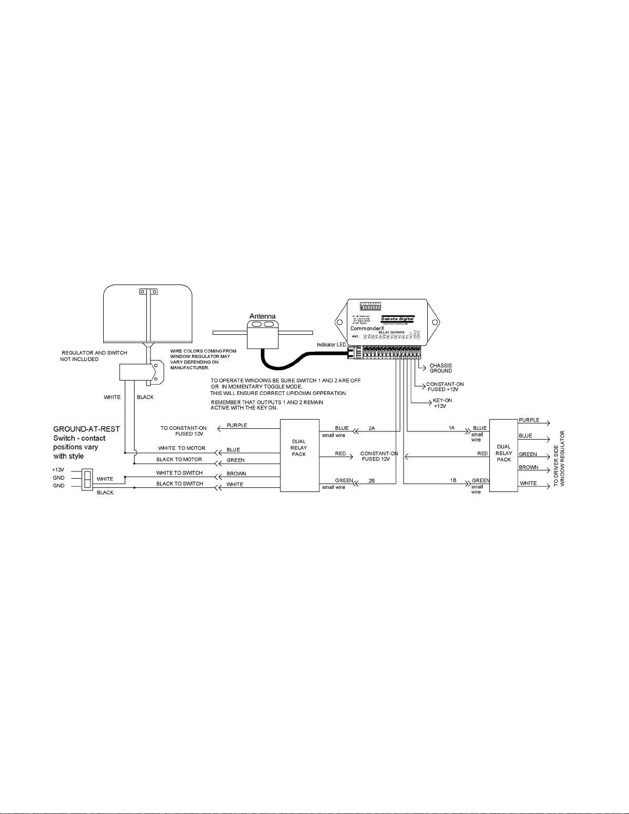
FIGURE 4 Connection to Specialty, Downs, Balls, GM, and other power window regulators
using a 5-wire or center-position grounding switch.
This wiring diagram can be used with most power window and switch combinations.
The existing switch (or in some cases relays) keep the two wires to the motor grounded when
the window is at rest. To move the window up, the “up” wire is switched to 12 volts while the
“down” wire remains grounded. To move the window down, the opposite occurs. For both the
existing switch and the remote system to be able to move the window, the wires between the
switch and the window regulator need to be cut and separated. These wires are then
connected to the supplied dual relay pack. One relay in the pack will roll the window up, the
other down.
While the remote system itself should not be mounted in the door, the relays can be.
Mount them so the wires are going out the bottom. This will prevent water from collecting
inside.The wiring for the passenger side is identical to the driver’s side.
6

FIGURE 5 Connection to power window regulators with a three wire 12 volt switch.
FIGURE 6 Connection to power windows with 4-wire switch (not center position grounding).
7

POWER TRUNK LIFT WIRING
The trunk lift motor is not included in the base package. These are available from
Dakota Digital separately.
FIGURE 7 Connection to power trunk lift motor.
SINGLE RELAY WIRING FOR AUXILIARY OUTPUTS
There are two single and two dual relay packs included with the CMDX. There are
additional relays available from Dakota Digital (RLY-1 & RLY-2), however any 12 volt,
automotive relay will work. This diagram will show how to wire a relay to supply +12V to the
desired load. Depending on the desired operation, a latching or momentary output could be
used.
FIGURE 8 Connection to relays for operating accessories with auxiliary outputs.
8

POWER DOOR LOCK WIRING
The trunk raise/lower channels can also be used for power door locks to add more
security to the vehicle. The door lock actuators are not included with the base package. These
are sold separately if needed for your application. The CMDX should be setup for momentary
toggling outputs to operate door lock motors, extended power to the lock motor could damage
the motor.
FIGURE 9 Connection to power door locks with 3-wire, +12V switch.
FIGURE 10 Connection to power door locks with 3-wire grounding switch.
9

POWER DOOR LOCK WIRING
FIGURE 11 Connection to power door locks with a 5-wire switch.
TRANSMITTER BUTTON NUMBERING OUTPUT CONTROLLED
10

11
OPERATION FOR MODE 1, DIP switch OFF momentary toggling outputs
The key chain transmitter has six buttons. They are labeled with roman numerals I, II,
III, IV, V, and VI. The red light next to the programming switches will flash once briefly each
time a button is pressed to verify the command has been received.
Button I controls outputs 1A and 1B, button II controls outputs 2A and 2B, button III
outputs 3A and 3B, button IV outputs 4A and 4B, button V outputs 5A and 5B, and button VI
outputs 6A and 6B.
There are 7 dip switches on the top of the CMDX. Switches 1 – 6 are the channel mode
control switches. Mode 1 is where the dip switch for a channel is OFF. This places that
channel in the momentary toggle mode.
In momentary toggle mode the first time a button is pressed output A is activated,
switched to ground, as long as the button is held. The next time the button is pressed output B
is activated as long as the button is held.
When the ignition key is on, the only buttons that will work are I and II Buttons III, IV, V,
and VI are disabled. Outputs 1A, 1B, 2A, and 2B stay active will the key on so door latches, or
other devices that are not intended to operate when the vehicle is running should not be
controlled by these outputs. This safety feature will not allow the doors or trunk to accidentally
release while the vehicle is in motion if connected to the appropriate output.
OPERATION FOR MODE 2, DIP switch ON momentary and latching outputs
The key chain transmitter has six buttons. They are labeled with roman numerals I, II,
III, IV, V, and VI. The red light next to the programming switches will flash once briefly each
time a button is pressed to verify the command has been received.
Button I controls outputs 1A and 1B, button II controls outputs 2A and 2B, button III
outputs 3A and 3B, button IV outputs 4A and 4B, button V outputs 5A and 5B, and button VI
outputs 6A and 6B.
There are 7 dip switches on the top of the CMDX. Switches 1 – 6 are the channel mode
control switches. Mode 2 is where the dip switch for a channel is ON. This places that
channel in the momentary latch mode.
In momentary latch mode output A is activated, switched to ground, as long as the
button is held, each time the button is pressed. Output B is the latching output. The first the
button is pressed outputs B is latched on, switched to ground. The next time the button is
pressed output B is shut off.
When the ignition key is on, the only buttons that will work are I and II Buttons III, IV, V,
and VI are disabled. Outputs 1A, 1B, 2A, and 2B stay active while the key on so door latches,
or other devices that are not intended to operate when the vehicle is running should not be
controlled by these outputs. This safety feature will not allow the doors or trunk to accidentally
release while the vehicle is in motion if connected to the appropriate output.

12
REMOTE SYSTEM TRANSMITTER LOCK FUNCTION
Due to the long range of this system, some customers may wish to avoid accidentally pressing a button
and opening a door when they are out of sight of the vehicle. Pressing buttons V and VI at the same time will
lock the receiver from activating any of the outputs. It will remain locked until buttons V and VI are pressed again.
To lock the system:
1. Press and release buttons V and VI at the same time.
2. Press one of the other buttons to verify that the system is locked.
To unlock the system:
1. Press and release buttons V and VI at the same time.
2. Press one of the other buttons to verify that the system is operating normally.
PROGRAMMING SWITCHES
There are seven programming switches located at the top of the CMDX. They are used to set up the
operation of the remote system and to enter the programming mode to program additional transmitters. For
output A momentary and output B latching the switch for that channel should be ON. For toggling momentary
outputs the switch for the channel should be OFF. Switch 7 is used for programming additional transmitters,
covered below in detail.
Switch #1 Select operation mode. (changes output 1A and 1B, momentary or momentary/latch)
Switch #2 Select operation mode. (changes output 2A and 2B, momentary or momentary/latch)
Switch #3 Select operation mode. (changes output 3A and 3B, momentary or momentary/latch)
Switch #4 Select operation mode. (changes output 4A and 4B, momentary or momentary/latch)
Switch #5 Select operation mode. (changes output 5A and 5B, momentary or momentary/latch)
Switch #6 Select operation mode. (changes output 6A and 6B, momentary or momentary/latch)
Switch #7 Enter testing and programming mode.
BATTERY REPLACEMENT
Should the transmitter function become weak or erratic, the battery in the key chain transmitter may be
weak. An indication of a weak battery is that the red indicator may have a dim glow to it when any button is
pressed. The battery is replaced in the following manner:
1. Use a small, straight screwdriver to pry the two halves apart at the key ring attachment.
2. Carefully separate the two case halves.
3. Remove the battery, noting the (+) and (-) position.
4. Replace the battery with a new 12 volt type GP23A battery which is available at most electronic stores
(Radio Shack, battery stores, etc.).
5. Carefully replace the top cover and snap the two pieces together.
INSTRUCTIONS FOR TESTING AND PROGRAMMING TRANSMITTERS
All of the transmitters to be programmed into the system should be available. This sequence will erase
any previously programmed transmitters. If a transmitter is lost or stolen, go through the programming sequence
with the remaining transmitters and the lost one will be erased. The programming light is located next to terminal
strip, next to the ground connection. The IGN terminal must be connected to enter the programming/testing mode
as well as the power and ground terminals.
Placing receiver into programming/testing mode.
1. Turn Switch #7 on.
2. Turn on the ignition switch(applying power to the IGN terminal).
3. The red programming light should come on and remain on steady.
Testing the transmitters.
4. Press button V. The programming light should flash as long as the button is held.
5. Press button I. The programming light will flash if the transmitter is currently programmed in. This will
also resyncronize the transmitter with the decoder. The number of flashes will indicate the transmitter
number.
Programming the transmitters.
6. Turn Switch #7 off. The programming light should go off.
7. Press and release button number III. The programming light should come on.
8. Press and release button number III again. The programming light should flash and then go out. It will
flash once for the first transmitter, twice for the second, etc.
9. The transmitter is now stored. If you have more transmitters, take the next transmitter and go back to
step 7.

13
10. When you are finished, turn the ignition key off to exit the programming mode and restart the system.

TROUBLE SHOOTING GUIDE
Symptom Possible Problem Solution
----------------------------------------------------------------------------------------------------------------------------------------------------
System will not operate. Receiver is not getting Check 12 volt connection.
power. Check ground connection.
Checkfuses.
Transmitter is locked. Press V and VI at the same
time.
Antenna is not plugged in. Check antenna connection.
System is in test/program mode Check Switch #7
Door latch actuators ‘jump’ Weak or poor 12 volt connection. Check 12 volt connection to
or ‘chatter’. Relays.
Move to new terminal point.
Windows change direction in Over loaded 12 volt power circuit. Place receiver and windows on
mid-travel. separate circuits.
Check for loose connections.
Increase wire size on power.
Weak car battery. Recharge or replace car battery.
Transmitter signal is being disrupted. Move antenna away from power
wires.
Outputs 1 and 2 work, but all others Ignition key is on. Turn off ignition key.
will not . IGN terminal has 12 volts at all times. Move IGN wire to a
terminal
that is powered only when the
key is on.
Transmitter has very short range Transmitter battery is weak. See Battery Replacement.
on all functions. Antenna needs repositioning Move antenna out away from
any high current wires.
If none of these solutions solve the problem, or the problem occurring is not listed here, please call the Dakota
Digital technical assistance line at (605) 332-6513 for further assistance or email to:
CMDX COMMANDER SERIES REMOTE ENTRY SYSTEM LIMITED LIFETIME WARRANTY
DAKOTA DIGITAL (the Company) warrants to the ORIGINAL PURCHASER of this remote control product that should any included
control relays, electronic module, or transmitters under normal use and condition, be proven defective in material or workmanship DURING
THE LIFETIME OF THE CAR IN WHICH IT WAS ORIGINALLY INSTALLED, such defect(s) will be repaired or replaced (at the Company’s
option) without charge for parts or labor directly related to repairs of the defect(s).
To obtain repair or replacement within the terms of this Warranty, the product is to be delivered with proof of warranty coverage (e.g.
dated bill of sale), specification of defects, transportation prepaid, to the factory. This Warranty is valid for the original purchaser only and may
not be transferred.
This warranty does not cover batteries, nor extend to damage to vehicle electrical system. This Warranty does not apply to any
product or part thereof which in the opinion of the Company has been damaged through alteration, improper installation, mishandling, misuse,
neglect, or accident.
This Warranty is in lieu of all other express warranties or liabilities. ANY IMPLIED WARRANTIES, INCLUDING ANY IMPLIED
WARRANTY OF MERCHANTABLITY, SHALL BE LIMITED TO THE DURATION OF THIS WRITTEN WARRANTY. ANY ACTION FOR
BREACH OF ANY WARRANTY HEREUNDER INCLUDING ANY IMPLIED WARRANTY OF MERCHANTABLITY MUST BE BROUGHT
WITHIN A PERIOD OF 30 MONTHS FROM DATE OF ORIGINAL PURCHASE. IN NO CASE SHALL THE COMPANY BE LIABLE FOR ANY
CONSEQUENTIAL OR INCIDENTAL DAMAGES FOR BREACH OF THIS OR ANY OTHER WARRANTY, EXPRESSED OR IMPLIED,
WHATSOEVER. No person or representative is authorized to assume for the Company any liability other that expressed herein in connection
with the sale of this product.
The Company does not warrant that this product cannot be compromised or circumvented. THE EXTENT OF THE COMPANY’S
LIABILITY UNDER THIS WARRANTY IS LIMITED TO THE REPAIR OR REPLACEMENT PROVIDED ABOVE AND, IN NO EVENT, SHALL
THE COMPANY’S LIABILITY EXCEED THE PURCHASE PRICE PAID BE THE PURCHASER FOR THE PRODUCT.
Some states do not allow limitations on how long an implied warranty lasts or the exclusion or limitation if incidental or consequential
damage so the above limitations or exclusions may not apply to you. This warranty gives you specific legal rights and you may also have
other rights which vary from state to state.
4510 W. 61ST St. N., Sioux Falls, SD 57107
Phone: (605) 332-6513 FAX: (605) 339-4106
www.dakotadigital.com
©Copyright 2005 Dakota Digital Inc.
14
Other manuals for COMMANDER Series
2
This manual suits for next models
1
Table of contents
Other Dakota Digital Control System manuals
Popular Control System manuals by other brands

CURB
CURB CURB Installation & user guide

Elsner
Elsner KNX CasaConnect KNX Installation, setting, operation

Burkert
Burkert NAMUR 6517 operating instructions

Briggs & Stratton
Briggs & Stratton Symphony II Installation & operator's manual

Raven
Raven SCS-330 Installation & service manual

Woodward
Woodward MicroNet TMR 5009 Installation/Hardware Manual