manuals.online logo
Brands
  1. Home
  2. •
  3. Brands
  4. •
  5. HEIDENHAIN
  6. •
  7. Control System
  8. •
  9. HEIDENHAIN TNC 150 B User manual

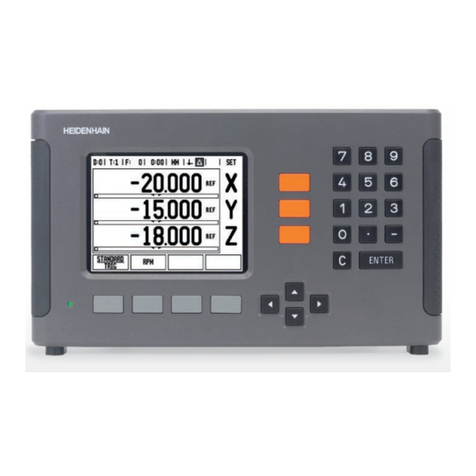
HEIDENHAIN TNC 150 B User manual

Other manuals for TNC 150 B

1

This manual suits for next models

1

Other HEIDENHAIN Control System manuals

HEIDENHAIN TNC 620 User manual

HEIDENHAIN

HEIDENHAIN TNC 620 User manual

HEIDENHAIN TNC 320 User manual

HEIDENHAIN

HEIDENHAIN TNC 320 User manual

HEIDENHAIN ITNC 530 - CONVERSATIONAL PROGRAMMING User manual

HEIDENHAIN

HEIDENHAIN ITNC 530 - CONVERSATIONAL PROGRAMMING User manual

HEIDENHAIN POSITIP 880 User manual

HEIDENHAIN

HEIDENHAIN POSITIP 880 User manual

HEIDENHAIN ITNC 530 - CONVERSATIONAL PROGRAMMING User manual

HEIDENHAIN

HEIDENHAIN ITNC 530 - CONVERSATIONAL PROGRAMMING User manual

HEIDENHAIN TNC 620 User manual

HEIDENHAIN

HEIDENHAIN TNC 620 User manual

HEIDENHAIN TNC 150 B User manual

HEIDENHAIN

HEIDENHAIN TNC 150 B User manual

HEIDENHAIN POSITIP 880 User manual

HEIDENHAIN

HEIDENHAIN POSITIP 880 User manual

HEIDENHAIN TNC 407 User manual

HEIDENHAIN

HEIDENHAIN TNC 407 User manual

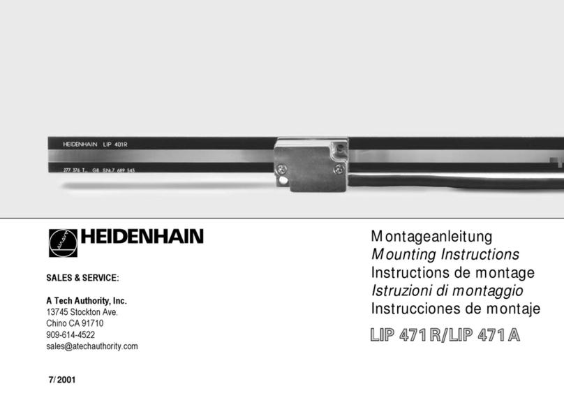
HEIDENHAIN LIP 471R User manual

HEIDENHAIN

HEIDENHAIN LIP 471R User manual

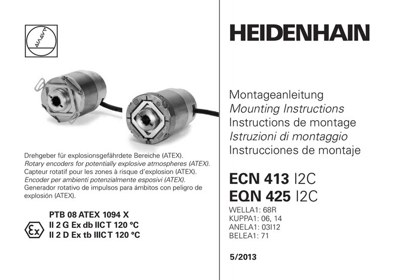
HEIDENHAIN ECN 413 2C User manual

HEIDENHAIN

HEIDENHAIN ECN 413 2C User manual

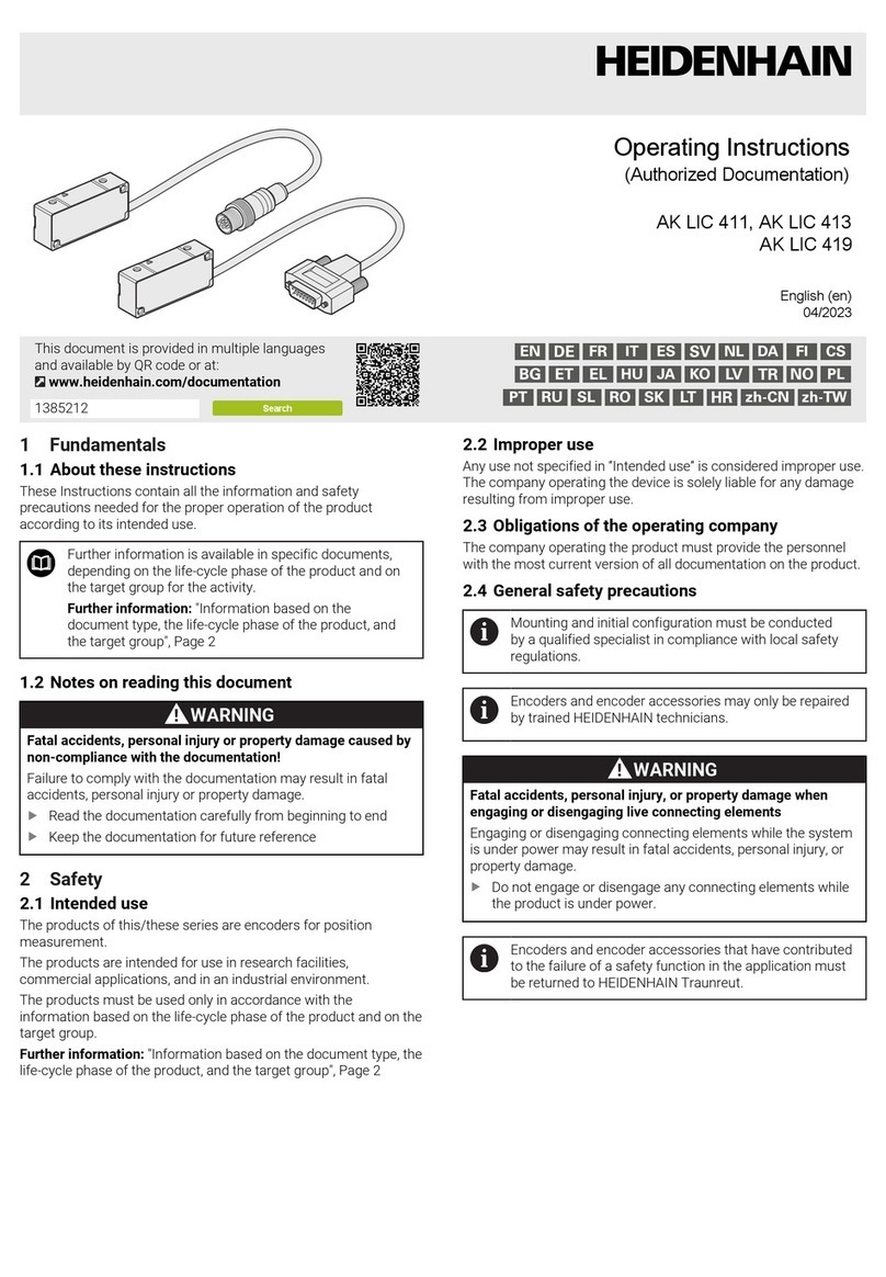
HEIDENHAIN AK LIC 413 User manual

HEIDENHAIN

HEIDENHAIN AK LIC 413 User manual

HEIDENHAIN TNC 620 Programming Station User manual

HEIDENHAIN

HEIDENHAIN TNC 620 Programming Station User manual

HEIDENHAIN LIF 181 R User manual

HEIDENHAIN

HEIDENHAIN LIF 181 R User manual

HEIDENHAIN ND 780 User manual

HEIDENHAIN

HEIDENHAIN ND 780 User manual

HEIDENHAIN ITNC 530 - CONVERSATIONAL PROGRAMMING User manual

HEIDENHAIN

HEIDENHAIN ITNC 530 - CONVERSATIONAL PROGRAMMING User manual

HEIDENHAIN TNC 620 User manual

HEIDENHAIN

HEIDENHAIN TNC 620 User manual

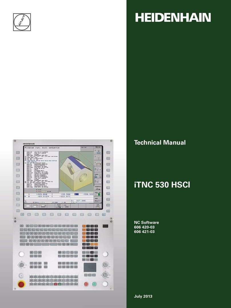
HEIDENHAIN iTNC 530 HSCI User manual

HEIDENHAIN

HEIDENHAIN iTNC 530 HSCI User manual

HEIDENHAIN CNC PILOT 640 User manual

HEIDENHAIN

HEIDENHAIN CNC PILOT 640 User manual

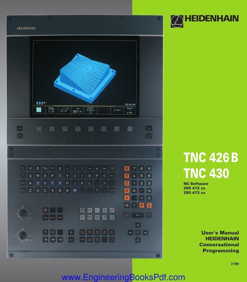
HEIDENHAIN TNC 426 B User manual

HEIDENHAIN

HEIDENHAIN TNC 426 B User manual

HEIDENHAIN AK ECM 2410 User manual

HEIDENHAIN

HEIDENHAIN AK ECM 2410 User manual

HEIDENHAIN TNC 320 User manual

HEIDENHAIN

HEIDENHAIN TNC 320 User manual

HEIDENHAIN TNC151B Operating instructions

HEIDENHAIN

HEIDENHAIN TNC151B Operating instructions

HEIDENHAIN TNC 370 D Manual

HEIDENHAIN

HEIDENHAIN TNC 370 D Manual

Popular Control System manuals by other brands

Comunello BORDER 400 Installation and user manual

Comunello

Comunello BORDER 400 Installation and user manual

Verlinde EUROBLOC Variator VTN Service manual

Verlinde

Verlinde EUROBLOC Variator VTN Service manual

Diginet DGOZ-TCSW-LR35 installation guide

Diginet

Diginet DGOZ-TCSW-LR35 installation guide

VADDIO ControlVIEW Xtreme manual

VADDIO

VADDIO ControlVIEW Xtreme manual

Duke HSHU 13 SERIES Installation and operation manual

Duke

Duke HSHU 13 SERIES Installation and operation manual

AIRTRONICS Blazer Sport manual

AIRTRONICS

AIRTRONICS Blazer Sport manual

Pentair Pool Products Compool Installation and user guide

Pentair Pool Products

Pentair Pool Products Compool Installation and user guide

ComfortNET CTK04 manual

ComfortNET

ComfortNET CTK04 manual

CAME G3000 installation manual

CAME

CAME G3000 installation manual

Idemia MorphoAccess VP MD installation guide

Idemia

Idemia MorphoAccess VP MD installation guide

Doosan DVF Series Operation user's manual

Doosan

Doosan DVF Series Operation user's manual

Axis P1445-LE-3 user manual

Axis

Axis P1445-LE-3 user manual

CNC-Step High-Z T-Series operating instructions

CNC-Step

CNC-Step High-Z T-Series operating instructions

Honeywell KAP 140 Maintenance manual

Honeywell

Honeywell KAP 140 Maintenance manual

Honeywell vk41 series Handbook

Honeywell

Honeywell vk41 series Handbook

Cypress HHR-3160 product manual

Cypress

Cypress HHR-3160 product manual

Zonex GEN II -VVT Installation and application manual

Zonex

Zonex GEN II -VVT Installation and application manual

Altronics K 9650 quick start guide

Altronics

Altronics K 9650 quick start guide

manuals.online logo
manuals.online logoBrands
  • About & Mission
  • Contact us
  • Privacy Policy
  • Terms and Conditions

Copyright 2025 Manuals.Online. All Rights Reserved.

RGB ELEKTRONIKA AGACIAK CIACIEK
SPÓŁKA JAWNA
Jana Dlugosza 2-6 Street
51-162 Wrocław
Poland
biuro@rgbelektronika.pl
+48 71 325 15 05
www.rgbautomatyka.pl
www.rgbelektronika.pl
DATASHEET
www.rgbautomatyka.pl
www.rgbelektronika.pl
OTHER SYMBOLS:
223 836 05
22383605, 223836 05, 223 83605, 223 836 05
HEIDENHAIN
YOUR
PARTNER IN
MAINTENANCE
At our premises in Wrocław, we have a fully equipped servicing facility. Here we perform all the repair
works and test each later sold unit. Our trained employees, equipped with a wide variety of tools and
having several testing stands at their disposal, are a guarantee of the highest quality service.
OUR SERVICES
ENCODERS
SERVO
DRIVERS
LINEAR
ENCODERS
SERVO AMPLIFIERS
CNC
MACHINES
MOTORS
POWER
SUPPLIERS
OPERATOR
PANELS
CNC
CONTROLS
INDUSTRIAL
COMPUTERS
PLC
SYSTEMS
Repair this product with RGB ELEKTRONIKA ORDER A DIAGNOSIS ∠
Buy this product at RGB AUTOMATYKA BUY ∠
-.,
PLC-Description
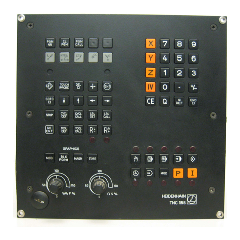
HEIDENHAIN TNC 150 B/TNC 150 0
Contouring Control
DR. JOHANNES HEIDENHAIN
Precision Mechanics, Optics and Electronics Precision Graduations
P.O.Box 1260. D-8225 Traunreut Telephone (08669) 31-O
Telex: 56831 Telegramme: DIADUR Traunreut
Issue 11184
Pocket for PLC-PROGRAMMING KEYBOARD-FOIL
Contents
Introduction
Section
A)
Page
5
Connection and technical data
Connection and technical data TNC 150 B
Connection and technical data TNC 150 Q
Connection of TNC 150 Q
Grounding diagram
Technical data for PLC
Layout of inputs and outputs of PLC-boards
PLC-boards PL 100 B/PL 110 B as first PLC-board
PLC-boards PL 100 B/PL 110 B as second PLC-board
EPROM for the PLC-Programme
B) . 6
B 1) 6
B 2) 7
B2.1) 7
B 2.2) 8
B 2.3) 9
B 2.4) 12
B 2.4.1) 12
B 2.4.2) 13
B 3) 14
Programming of the HEIDENHAIN PLC Cl
Description of the PLC-Commands c 1)
No Operation: NOP c 1.1)
Assignment: = c 1.2)
AND-Command: U c 1.3)
AND-Command with inverted operand: UN c 1.4)
OR-Command: 0 c 1.5)
OR-Command with inverted operand: ON C 1.6)
Exklusive OR-Command: X0 c 1.7)
Exklusiv OR-command with inverted operand: XON C 1.8)
Programming of logic sequences I c 1.9)
Logic sequences with U-commands c 1.9.1)
Logical sequences with UN-commands C 1.9.2)
Logical sequences with O-commands c 1.9.3)
Logic sequence with ON-commands c 1.9.4)
Logic sequence with XO/XON commands c 1.9.5)
Programming of an arbitrary logic sequence C 1.9.6)
Setting and resetting of a marker c 1.10)
Address allocation for PLC-markers c 2)
User markers: Address letter M C2.1)
Markers for the signal exchanges between PLC and NC:
Address letter M c 2.2)
Markers for the axis release: X, Y, Z, IV c 2.2.1)
Markers for axes in position: X, Y, Z, IV c 2.2.2)
Markers for traverse-dependent lubrication impulses: X, Y, Z, IV- C 2.2.3)
Markers for M-S-T-Code-Outputs C 2.2.4)
Markers for coded M-S-T-Code Outputs - C 2.2.4.1)
Markers for decoded M-Code output C 2.2.4.2)
Markers for analogue output of the spindle speed C 2.2.5)
Marker for tapping cycle C 2.2.6)
Markers for the currently activated axis button: X, Y, Z, IV- C 2.2.7)
Markers for selected operating mode C 2.2.8)
Markers for operating mode-code C 2.2.8.1)
Markers for the decoded operating ‘mode-code C 2.2.8.2)
Markers for the first PLC-program cycle after power on and
after interruption of PLC-programme C 2.2.9)
Markers affected by machine parameter 158 c 2.2.10)
15
15
15
15
16
16
16
17
17
17
18
18
19
20
21
22
22
23
24
24
24
24
25
25
26
26
28
30
31
32
32
32
32
33
33
Section Page
Markers for inhibiting buttons c 2.2.11) 34
Markers for control status and error messages ___ c 2.2.12) 36
Markers for inhibiting the Servo Loop C 2.2.13) 39
Markers for transfer of actual position values as
nominal values (Teach-in) C 2.2.14) 39
Markers for external buttons and switches C 2.2.15) 40
Marker-d for the PLC-Positioning C 2.2.16) 42
Code for the external selection of TNC-buttons - C 2.2.17) 44
PLC-Inputs and PLC-Outputs:
Address letters E, A C 2.3) 46
I Summary ___- C 2.3.1) 46
Bipolar PLC-outputs for PL 110 B C 2.3.2) 48
Output “Emergency Stop” C 2.3.3) 48
Counters -- c 3) 49
Timers __- c 4) 50
1 Macro-progralmmes 51
Selecting and exiting from the PLC-modes 51
“PLC Programme editor”:
PCE
button
0 52
Keyboard layout for PLC-programming 53
Button functions 54
Programming PLC-commands 55
Call-up of a specific PLC-command 55
Sequential checking of PLC commands 56
Deleting PLC-commands 56
Entering PLC-commands into an existing programme 56
Deleting a PLC-Programme 56
Transfer of a programme from the main memory into
read/write-store 57
Input/Output of PLC-programmes on magnetic tape 57
Operating mabde “PLC-Programme trace function”:
Operating mode “Table E/A/&T/M”:
Off-line PLC pr&rammmg
PLC-command format
PLC-Operation codes for PLC-Commands C 7.2) 61
PLC-Address for PLC-Commands c 7.3) 61
EPROM Add;ress list c 7.4) 61
Standard TNC 150 B 4 TNC 150 Q PLC-program description D) 62
Address list ,_ II D 1) 62
Reference listing for markers, inputs / outputs and timers - D 2) 64
Standard PLC-program for the TNC 150 B / TNC 1513 0 D 3) 68
Terminal layout for input / output signals for
TNC 150 B /TNC 150 Q D 4) 82
Programming list -_ El 83
List of machine paralmeters TNC 150 F) 88
List of markers for signal exchange between PLC and NC _ G) 92
3
This PLC-description is valid for the controls:
TNC 150versions with ilnterface for an external machine PLC
Transducer inputs: sinusoidal signals Transducer inputs: square wave signals’
TNC 150 B TNC 150 BR
TNC 150 F (without 3D-movement) TNC 150 FR
TNC-versions with PLC-power board(s)
Transducer inputs: sinusoidal signals Transducer inputs: squar’e wave signals
TNC 150 Q TNC 150 QR
TNC 150 W (without 3D-movement) TNC 150 WR
4
A) Introduction
Logiccircuits operate in binary i.e. two unique, dedicated switching states.
The two possible logic states will be represented by the figures “1” and “0” in this description.
Example:
Switch closed = “1”
Switch open = “0” ’
Lamp on = “1”
Lamp off = “0”
This relationship can be represented with the aid of a function table (truth table). The switch state is
represented as an input variable (operand) El and the lighted lamp as a logic result Al.
Truth Table:
Digital switching signals can be combined (logic circuits). The basic logic elements in the switching
algebra are: AND
OR
NOT
The logic results of digital switching signals can be realised in the following ways:
.through relays
.through integrated circuits
.through software programmes
Since the implementation of logic sequences using software programmes allows greater flexibility in the event
of alterations, the programmable interface (PLC = Programmable Logic Controller) has gained ground in the
application to machine tool control.
The PLC is integrated in the HEIDENHAIN control TNC 1510, giving the following advantages:
.The signals between NC and PLC are markers, making more input and output signals possible and the control
more flexible
.The hardware interface is simplified
.As the PLC programme can be entered at the control, an ex.ternal programming station is unnecessary
.When programming ,the PLC functions, an immediate check is possible
.Machine faults can b’e displayed on the screen
Please note:
We are constantly working on the further development of out TNC-Controls and a certain control may deviate
from the versions described within this manual.
5
15%, 48 ... 62 Hz
B) Connection and techlnical data
The HEIDENHAIN TNC 150 control is available in two basic versions:
TNC 150 B with interface for external machine adaptation (similar to TNC ‘145 C)
TNC 150 Q with external PLC-power board
Technical data for controls TNC 150 B/TNC 150 Q
Mains voltage supply
Power consumption
Ambient temperature
Selectable 100/l 20/l 40/200/220/240 V + 10 % /
ca. 60 W (with 9” or 12” ‘vDU-screen unit)
Operation 0 ... + 45’C (+ 32 ... + 113’F)
Storage - 30 ... + 70°C (-- 22 ... + 158°F)
Weight Control: 11.5 kg
9”-VDU-screen unit: 6.8 kg,
12”-VDU-screen unit: 10 kg,
PC-power board: 1.2 kg (l-NC 150 Q)
Please note:
All inputs and outputs of the controls TNC 150 B/TNC 150 Q rnay only be connected to circuits having
protective low voltage.
B 1) Connection and technical data TNC 150 B
TNC 150 B is adapted to the machine externally.
The interface of the TNC 150 B function via an internal PLC-program (see section D 3). This program may, if
required, be subjected to slight alterations by the machine tool nanufacturer.
With TNC 150 B only the
inputs EO - E23
and
outputs A0 - A22
are used an extended externally via connectors Jl - J6 (see secl-ion D)
Technical data for control inputs
Potential-free opto-couplers (switched into groups)
Operating voltage max. 30 V; filtered
Optocouplers switched through 2 15v
Optocouplers open f 8V
Loading per input L 1OmA
Technical data of control outputs
Potential-free relay contacts (switched into groups)
Operating voltage max. 30 V =/min. 15 V =/
Operating current per contact max. 50 mA
Permissible load Resistive load;
inductive load only with quenching diode parallel to inductivity.
To prevent welding of contacts during a short circuit, a current limiting resistor of 47 ohms is switched into
series with each contact.
Detailed information coincerning the connection and adaptation of the TNC 150 B is available in the special
interfacing manual.
6
B 2) Connection and technical data of TNC 150 Q
B 2.1) Connection of TNC 150 Q
With TNC 150 Q a clear and simple arrangement of the control-adaptation system is possible.
Due to loss of power the inputs and outputs of the PLC have been accomodated on one (or two) boards which
are separated from the TNC-unit.
Board 2: Board 1:
PL 100 B Id.-No. 223 836 05 PL 100 B Id.-No. 223 836 05
PL 110 B Id:No. 223 216 05 PL 110 B Id:No. 223 216 05 Multipoint connectors Jl, J2 and J3
for analogue signals
Air exit Air exit (Description: see interface manual TNC 150)
4
+zv
4 4
4+&V 4 f f I
I
1'
L
0
11
0 /
-TTl
I \ I-, 1 Transducers
/
1111 IHandwheel
Magnetic tape
cassette unit
t’ ov t t t
!!’ 7
Air entry VDU-unit
max. 20m
I I
Connecting cable 2 Connecting cable 1
Id.-No. 222 662 .. Id.-Nr. 223 616 __
(12 x 2 x 0.14) (12 x 2 x 0.14)
Standard length 1 m: Standard length 5 m:
Id:No. 222 662 01 Id.-No. 223 616 01
Special lengths on request Special lengths on request
(max. 5 m) (max. 20 m)
?
0
1 Installation sizes ::
E
0
2 Screen contact
,
0
‘iease note:
The total length of cable between TNC 150 Q and Board 2 must not exceed 20 m.
The cable length between Board 1 and Board 2 must not e!xceed 5 m.
7
B 2.2) Grounding diagram
-
L-.-.
-----
----
,I3
-.-.-. .-
1
-.-.-.-.-.-.2i
N
+
-.-.
J
1
I
I
I
I
I
I
I
I
I
I
I
I
I
I
I
I
I
I
I
-4 I
I
I
ci
-
/.. .
q# .$sg
Isa.- &”
c;i.
u
k I
Ct2.
L i b (Z
-.-.-. . . --I
_-_---
_--_--
I L---------.
1
r
_.-.-.-.-.-.
19
8