Dakota Digital CMD-2000 Series User manual

CMD-2000 SERIES REV A
REMOTE UP/DOWN DUAL WINDOW CONTROL
OR LOCK/UNLOCK CONTROL
INTRODUCTION
Thank you for purchasing the CMD-2000 series Remote Window Control from Dakota
Digital, Inc. This, along with many other products that Dakota Digital, Inc. has to offer, represents
the latest in electronics technology for the street rod, classic car and truck, and any custom
vehicle.
The CMD-2000 Remote Window Control system comes complete with receiver, two key
chain transmitters, wiring harness, two dual relay packs, and emergency release switch. An
emergency release switch can be concealed on the underside of the vehicle should the door ever
be closed with the transmitters inside and you on the outside. Pressing this button will allow
reentry to the vehicle.
INSTALLATION
While installation of the CMD-2000 is very straightforward, paying a little attention here and
planning out how the system will fit into your specific vehicle will save some time in the long run.
The receiver should be mounted under the dash up on the fire wall for best access to wiring.
The kick panel is also another good location for the receiver.
Connect the CMD-2000 system as is shown in the wiring diagram. While the wiring diagram
is self explanatory, there are several key areas to pay particular attention to. First, the 12 volt
source to the relay packs should be able to supply up to 30 amps. This should have power
whether the key is on or off. The CMD-2000 should only be connected to a 12 volt battery for power
and never solely to a battery charger. The relay packs will typically be mounted inside the doors to
have the fewest wires running through the door jam. The relay packs should be mounted with the
wires exiting the bottom to prevent water from collecting inside the sockets.
ADDITIONAL TRANSMITTERS
The transmitters supplied with your remote system are serial number coded for security. Each
unit can “learn” up to 4 transmitters. It is also possible to program one transmitter into more than one
receiver. If you have more than one vehicle with the CMD-2000 system you can program all of the
transmitters into both units. Transmitters from other manufacturers, such as car alarm systems, will
not work with the CMD-2000.
in-line FUSE RED: +12 BATTERY
BLACK: GROUND
YELLOW
WHITE
GREEN
BLUE
CHANNEL 4
CHANNEL 3
CHANNEL 1
CHANNEL 2
All channels must
be connected to
relays if they are
used.
PINK
PURPLE
BROWN
CHANNEL 7
CHANNEL 6
CHANNEL 5
ANTENNA,
DO NOT GROUND
DAKOTA DIGITAL
not used
not used
GROUND
CH 1
CH 2
1

2
Wiring harness color code.
GREEN driver’s window up relay
RED constant 12 volt battery source
BLUE passenger’s window up relay
BLACK chassis ground
WHITE driver’s window down relay
YELLOW passenger’s window down relay
PINK or GRAY CHANNEL 7 relay (optional)
PURPLE CHANNEL 6 relay (optional)
BROWN CHANNEL 5 relay (optional)
The remote system output wires are negative switched outputs designed to turn on external
relays. These outputs can only handle 0.25 amps and must be used with a relay. Two dual relay
packs are supplied in the kit. To use all 7 channels you will need to purchase three additional
relays.
WINDOW CONTROL OPERATION
Each key chain transmitter has four buttons. Each button will activate its own independent
channel when pressed. Also, an additional 3 channels can be activated by pressing button 1 and
one of the other three buttons at the same time.
•Button 1 activates the driver’s window up. The window will continue to move as long as the
button is held. Button 3 activates the driver’s window down.
•Button 2 activates the passenger’s window up. Button 4 activates the passenger’s window
down.
•Pressing buttons 1 and 2 at the same time can activate an external relay on Channel 5.
•Pressing buttons 1 and 3 at the same time can activate an external relay on Channel 6.
•Pressing buttons 1 and 4 at the same time can activate an external relay on Channel 7.
The emergency release switch can be wired to roll the driver’s window down to provide
emergency entry to the vehicle.
LOCK/UNLOCK OPERATION
Each key chain transmitter has four buttons. Each button will activate its own independent
channel when pressed. Also, an additional 3 channels can be activated by pressing button 1 and
one of the other three buttons at the same time.
•Button 1 activates the door actuator to lock the doors. Button 3 activates the door actuator to
unlock the doors. The door actuator will remain powered for as long as the button is held. The
buttons should not be held more than a couple of seconds to avoid damaging the door lock
actuators.
•Pressing button 2 can activate an external relay on Channel 2. This can be used for a trunk
latch release or other function.
•Pressing button 4 can activate an external relay on Channel 4.
•Pressing buttons 1 and 2 at the same time can activate an external relay on Channel 5.
•Pressing buttons 1 and 3 at the same time can activate an external relay on Channel 6.
•Pressing buttons 1 and 4 at the same time can activate an external relay on Channel 7.

Two additional wires will need to be passed through each door, along with the other power
window wires. This should be done using a flexible rubber tube or rubber grommet to protect the
wires, or by using the optional DAKOTA DIGITAL, INC. MAGNUM SHOOTERS. MAGNUM
SHOOTERS will eliminate the wires running through the door jambs entirely for the cleanest
appearance possible. When these highly conductive brass contacts are mounted to the door and
to the door jamb they eliminate the wires completely. If you would like to use MAGNUM
SHOOTERS they can be ordered directly from DAKOTA DIGITAL, INC. by calling toll free 1-800-
852-3228. Using either the flexible rubber tube, or MAGNUM SHOOTERS, route the remaining
wires under the dash for the best location and appearance.
WIRING DIAGRAMS
3
Fused 12V power.
Do not
connect.
Fused 12V power.
To solenoid or other device.
Wiring a relay to one of the channel outputs
87
BLACK
BLUE 86
85
30
GREEN
RED
WHITE To CMD-2000 channel output.
Using a dual relay pack to operate solenoids or door actuators.
The blue wire can be used for one channel and the green wire for another channel.
FUSED 12V POWER
To solenoid or door actuator.
Do not connect.
Fused 12V power. PURPLE
GREEN
BROWN
WHITE
BLUE
RELAY RED
small wire
GREEN
PACK
BLUE
small wire
DUAL
To CMD-2000
Channel output.
To CMD-2000
Channel output.

GROUND-AT-REST
Switch - contact
positions vary
with style
GND
GND
+12V
BLACK TO MOTOR
WHITE TO MOTOR
BLACK TO SWITCH
WHITE TO SWITCH
FUSED 12V
TO CONSTANT-ON
BLACK
WHITE
WHITE BLACK
BLUE
GREEN
WHITE
BROWN
PURPLE
CHASSIS
GROUND
PACK
RELAY
DUAL
CONSTANT-ON
PACK RED
small wire
GREEN GREEN
FUSED 12V
small wire
BLUE
RELAY
DUAL
BLACK
WHITE
RED
BLUE GREEN
wire
small
YELLOW small
wire
BLUE
GREEN
TO PASSENGER SIDE
WINDOW REGULATOR
WHITE
BROWN
PURPLE
BLUE
NOT INCLUDED
REGULATOR AND SWITCH
MANUFACTURER.
VARY DEPENDING ON
WINDOW REGULATOR MAY
WIRE COLORS COMING FROM
CONSTANT-ON
FUSED +12V RED SEALED
SWITCH
Driver's Window
Emergency Entry
Switch
TAP INTO
WHITE
WIRE
FROM
REMOTE
GROUND
Connection Ball's, GM,
Specialty, Dakota Digital,
Springfield Streed Rod,
and similiar power
window systems.
ANTENNA,
DO NOT GROUND
DAKOTA DIGITAL
not used
not used
GROUND
CH 1
CH 2
4

POWER WIRES
NOT GROUND-AT-REST
4-WIRE or 3-WIRE
BLUE
ON POWER WINDOW SWITCH
IS NO LONGER CONNECTED.
CONNECTING A +12V WIRE
DO NOT CONNECT
DAMAGE THE REMOTE
CONTROL UNIT!
NOTE THAT +12V WIRE
TO THE SWITCH WILL
CHASSIS
GROUND
GROUND
CHASSIS
BLACK
BLUE
REGULATOR AND SWITCH
NOT INCLUDED
FUSED +12V
TO CONSTANT-ON
BLACK
CONNECT TO
RELAY RED GREEN
RELAY
BLUE
WINDOW REGULATOR
TO PASSENGER SIDE
small
wire
RED
GREEN
SWITCH
WINDOW MOTOR WIRES
WHITE
BROWN
GREEN PACK CONSTANT-ON
FUSED +12V
GREEN
PACK
BLUE WHITE
BROWN
wire
small
BLUE
PURPLE
CHASSIS
GROUND
DUAL
BLACK
CONSTANT-ON
FUSED +12V RED
WHITE
DUAL
YELLOW
PURPLE
BLUE
GROUND
TAP INTO
WHITE
WIRE
FROM
REMOTE
Driver's Window
Emergency Entry
Switch
SEALED
SWITCH
Connection to
4-wire, center open
power window
switches.
ANTENNA,
DO NOT GROUND
DAKOTA DIGITAL
not used
not used
GROUND
CH 1
CH 2
5

TO CONSTANT-ON
FUSED +12V
FUSED +12V
TO CONSTANT-ON
SWITCH
POWER WINDOW SPLICE
GREEN
DO NOT USE
DO NOT USE WHITE
BROWN
PURPLE
BLUE RELAY CONSTANT-ON
small wire
GREEN
PACK
GREEN
FUSED +12V
small wire
BLUE
DUAL RED
WHITE
CONNECT TO
an additional relay module
Special regulator or
of wiring connection
required for this style
GROUND
REGULATOR AND SWITCH
NOT INCLUDED
FUSED +12V
CONSTANT-ON
CHASSIS
GROUND
RED
BLACK
RELAY
PACK
DUAL
BLUE small wire
GREEN
RED
YELLOW BLUE
small
wire
TO PASSENGER SIDE
WINDOW REGULATOR
GREEN
BROWN
WHITE
PURPLE
BLUE
GROUND
SEALED
SWITCH
Driver's Window
Emergency Entry
Switch
TAP INTO
WHITE
WIRE
FROM
REMOTE
ANTENNA,
DO NOT GROUND
DAKOTA DIGITAL
not used
not used
GROUND
CH 1
CH 2
6

5-WIRE
SWITCH
GROUND
+12V (BATT)
GROUND WHITE
GREEN
BROWN
PURPLE
BLUE
GROUND
+12V BATTERY
WHITE
GREEN
+12V BATTERY
small wire
small wire
GREEN
RED
BLACK
RED
BLUE+12V BATTERY
Connection to door lock motors with a
5-wire switch.
ANTENNA,
DO NOT GROUND
DAKOTA DIGITAL
not used
not used
GROUND
CH 1
CH 2
7

WHITE
GREEN
BROWN
PURPLE
BLUE
GROUND
+12V BATTERY
WHITE
GREEN
+12V BATTERY
small wire
small wire
GREEN
RED
BLACK
RED
BLUE+12V BATTERY
GROUND
Connection to door lock motors
directly without a switch.
ANTENNA,
DO NOT GROUND
DAKOTA DIGITAL
not used
not used
GROUND
CH 1
CH 2
8

DO NOT CONNECT
GND
+12V
GND
DOOR LOCK
SWITCH
FACTORY DOOR
LOCK SYSTEM
GROUND
+12V BATTERY
WHITE
GREEN
+12V BATTERY
small wire
small wire
GREEN
RED
BLACK
RED
BLUE
+12V BATTERY
Connection to factory door
lock motors with a 3-wire
switch.
* wire colors listed in
( ) are for alternate
relay sockets found
in some units.
ANTENNA,
DO NOT GROUND
DAKOTA DIGITAL
not used
not used
GROUND
CH 1
CH 2
9

TECHNICAL SUPPORT
If you need any assistance with or have any questions about the wiring or operation of your CMD-2000 remote
system, please call the Dakota Digital technical assistance line at (605) 332-6513 or email us at
TRANSMITTER PROGRAMMING
All of the transmitters to be programmed into the system should be available. This sequence will erase any
previously programmed transmitters. If a transmitter is lost or stolen, go through the programming sequence with the
remaining transmitters and the lost one will be erased. The programming light (LED) is located on the side opposite
the antenna, next to the programming switch.
1. Press and release the programming switch 3 times. The LED should come on and remain on steady.
2. Press button 1 on the first remote. The LED should go out and then come back on steady.
3. Press button 1 on the second remote. The LED should go out and then come back on steady.
4. Repeat this for up to 4 remotes total.
5. When all of the remotes have been programmed in, wait for the LED to go out. The system will now operate
normally with all of the remotes.
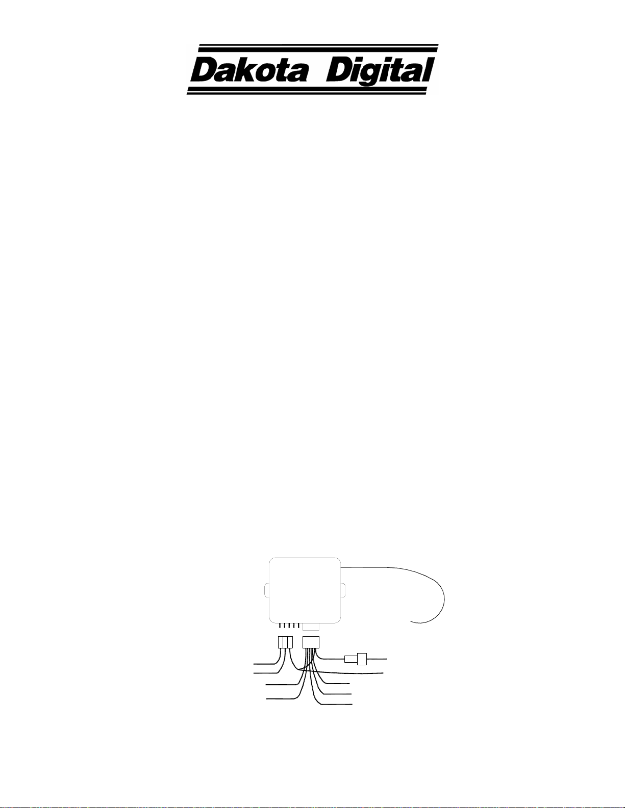
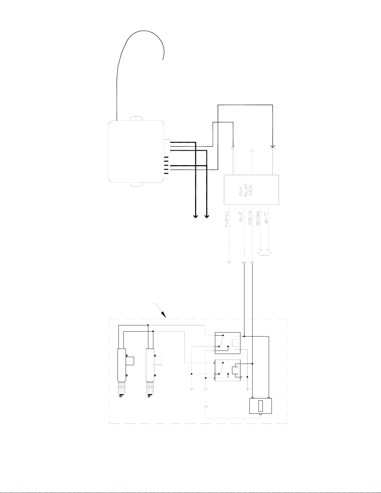
LED
wire harness
programming
switch
BATTERY REPLACEMENT
Should the transmitter function become weak or erratic, the battery in the key chain transmitter may be weak. An
indication of a weak battery is that the red indicator may have a dim glow to it when either button is pressed. If this
occurs, first check the system by using the second transmitter provided. If the second transmitter functions properly,
replace the battery in the defective transmitter by the following method:
A. Use a small, flat screw driver or knife to pry the case apart next to the chain.
B. Carefully separate the two case halves.
C. Remove the battery noting the (+) and (-) position.
D. Replace the battery with a new 12 volt type GP23A battery which is available at most electronic stores (Radio
Shack, etc.).
E. Carefully replace the top cover snap it into place.
F. Check transmitter function.
CMD-2000 REMOTE CONTROL DOOR OPENER SYSTEM
LIMITED LIFETIME WARRANTY
DAKOTA DIGITAL, INC. (the Company) warrants to the ORIGINAL PURCHASER of this remote control product that should any included control relay(s), electronic
module, or transmitters under normal use and condition, be proven defective in material or workmanship DURING THE LIFETIME OF THE CAR IN WHICH IT WAS
ORIGINALLY INSTALLED, such defect(s) will be repaired or replaced (at the Company's option) without charge for parts or labor directly related to repairs of the
defect(s).
To obtain repair or replacement within the terms of this Warranty, the product is to be delivered with proof of warranty coverage (e.g. dated bill of sale), specification
of defect(s), transportation prepaid, to the factory. This Warranty is valid for the original purchaser only and may not be transferred.
This Warranty does not cover batteries, nor extend to damage to vehicle electrical system. This Warranty does not apply to any product or part thereof which in the
opinion of the Company has been damaged through alteration, improper installation, mishandling, misuse, neglect, or accident.
This Warranty is in lieu of all other express warranties or liabilities. ANY IMPLIED WARRANTIES, INCLUDING ANY IMPLIED WARRANTY OF MERCHANTABILITY,
SHALL BE LIMITED TO THE DURATION OF THIS WRITTEN WARRANTY. ANY ACTION FOR BREACH OF ANY WARRANTY HEREUNDER INCLUDING ANY
IMPLIED WARRANTY OF MERCHANTABILITY MUST BE BROUGHT WITHIN A PERIOD OF 30 MONTHS FROM DATE OF ORIGINAL PURCHASE. IN NO CASE
SHALL THE COMPANY BE LIABLE FOR ANY CONSEQUENTIAL OR INCIDENTAL DAMAGES FOR BREACH OF THIS OR ANY OTHER WARRANTY, EXPRESSED
OR IMPLIED, WHATSOEVER. No person or representative is authorized to assume for the Company any liability other than expressed herein in connection with the
sale of this product.
The Company does not warrant that this product cannot be compromised or circumvented. THE EXTENT OF THE COMPANY'S LIABILITY UNDER THIS
WARRANTY IS LIMITED TO THE REPAIR OR REPLACEMENT PROVIDED ABOVE AND, IN NO EVENT, SHALL THE COMPANY'S LIABILITY EXCEED THE
PURCHASE PRICE PAID BY THE PURCHASER FOR THE PRODUCT.
Some states do not allow limitations on how long an implied warranty lasts or the exclusion or limitation if incidental or consequential damage so the above limitations
or exclusion may not apply to you. This Warranty gives you specific legal rights and you may also have other rights which vary from state to state.
4510 W. 61ST St. N., Sioux Falls, SD 57107
Phone: (605) 332-6513 FAX: (605) 339-4106
www.dakotadigital.com
©Copyright 2004 Dakota Digital Inc.
10
Other manuals for CMD-2000 Series
1
Table of contents
Other Dakota Digital Remote Control manuals