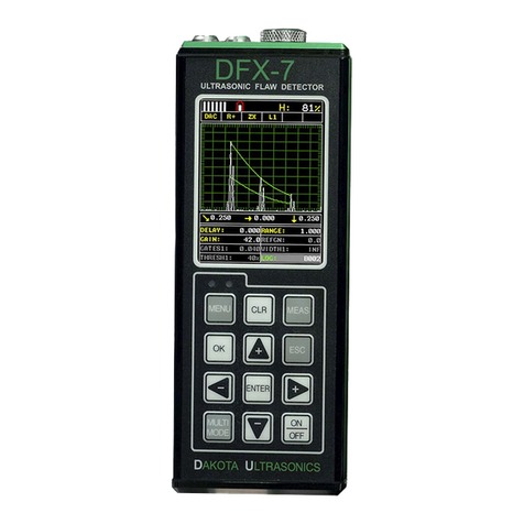
DAKOTA ULTRASONICS DFX-7 User manual

OPERATION MANUAL
DAKOTA ULTRASONICS
D
DF
FX
X-
-7
7
Ultrasonic Flaw Detector
(Manual 2 of 2)
P/N P-220-0006 Rev 2.0, July 2017


CONTENTS
CHAPTER ONE INTRODUCTION ...................................................................... 1
1.1 GENERAL DISCLAIMER .......................................................................................................... 1
1.2 ELECTRICAL WARNING ......................................................................................................... 2
CHAPTER TWO QUICK START GUIDE ............................................................ 3
2.1 GAUGE TYPE ....................................................................................................................... 3
2.2 BASIC FLAW SETUP REFERENCE .......................................................................................... 3
2.3 TOP & SUBMENU REFERENCE .............................................................................................. 4
2.4 LOADING THE DEFAULT SETUP ............................................................................................. 5
CHAPTER THREE KEYBOARD, MENU, & CONNECTOR REFERENCE ........ 7
3.1 MENU KEY (OPERATION & SUB MENUS) ........................................................................... 7
3.2 PROBE – MENU ................................................................................................................ 9
3.3 CAL – MENU .................................................................................................................... 9
3.4 DISP (DISPLAY) – MENU ................................................................................................. 10
3.5 TUNE – MENU ............................................................................................................... 10
3.6 GT1 – MENU .................................................................................................................. 11
3.7 GT2 – MENU .................................................................................................................. 12
3.8 TRIG – MENU ................................................................................................................ 12
3.9 AWS – MENU ................................................................................................................. 13
3.10 TCG – MENU ............................................................................................................... 13
3.11 DAC – MENU ............................................................................................................... 14
3.12 DGS – MENU ............................................................................................................... 14
3.13 SETUP – MENU ........................................................................................................... 15
3.14 DATA – MENU ............................................................................................................. 16
3.15 UTIL (UTILITIES) – MENU .............................................................................................. 16
3.16 XFER (TRANSFER) – MENU .......................................................................................... 17
3.17 CLR (CLEAR) KEY ..................................................................................................... 17
3.18 MEAS (MEASUREMENT MODE) KEY .............................................................................. 17
3.19 OK KEY ...................................................................................................................... 18
3.20 ESC KEY .................................................................................................................... 18
3.21 ARROW KEYS ............................................................................................................... 18
3.22 ENTER KEY ................................................................................................................. 18
3.23 MULTI MODE KEY ..................................................................................................... 18
3.24 ON/OFF KEY .............................................................................................................. 19
3.25 DFX-7 OVERVIEW ............................................................................................................ 19
3.26 NAVIGATING THE HOT MENU ............................................................................................. 21

3.27 TOP & BOTTOM END CAPS ............................................................................................... 22
TRANSDUCER CONNECTORS .................................................................................................... 23
PROBE ZERO DISK & BATTERY COVER ..................................................................................... 23
USB-C CONNECTOR ................................................................................................................ 23
CHAPTER FOUR SETTING UP FOR MEASUREMENT ................................. 24
4.1 SELECTING DISPLAY VIEW .................................................................................................. 24
4.2 ADJUSTING THE DISPLAY .................................................................................................... 25
SETTING DELAY ....................................................................................................................... 25
4.3 GAIN ................................................................................................................................. 28
4.4 GATES ............................................................................................................................... 31
4.5 ACTIVATING AND SETTING UP A GATE ................................................................................. 31
CHAPTER FIVE CALIBRATION ...................................................................... 36
5.1 SETTING UP FOR CALIBRATION .......................................................................................... 36
5.2 STRAIGHT BEAM CALIBRATION ........................................................................................... 41
5.3 ANGLE BEAM CALIBRATION ................................................................................................ 47
CHAPTER SIX TRIGONOMETRY MODE ........................................................ 51
6.1 INTRODUCTION TO TRIG .................................................................................................... 51
6.2 ADDITIONAL COMMENTS ..................................................................................................... 51
6.3 SETUP TRIGONOMETRY MODE............................................................................................ 52
CHAPTER SEVEN AWS – WELD INSPECTION ............................................ 56
7.1 INTRODUCTION TO AWS ..................................................................................................... 56
7.2 ADDITIONAL COMMENTS ..................................................................................................... 56
7.3 SETUP AWS ...................................................................................................................... 56
CHAPTER EIGHT DISTANCE AMPLITUDE CORRECTION (DAC) ............... 61
8.1 INTRODUCTION TO DAC ..................................................................................................... 61
8.2 ADDITIONAL COMMENTS ..................................................................................................... 61
8.3 CREATING A DAC CURVE ................................................................................................... 62
CHAPTER NINE TIME CORRECTED GAIN (TCG) ......................................... 67
9.1 INTRODUCTION TO TCG ..................................................................................................... 67
9.2 ADDITIONAL COMMENTS ..................................................................................................... 67
9.3 CREATING A TCG CURVE ................................................................................................... 67
CHAPTER TEN DISTANCE, GAIN, SIZE (DGS) ............................................. 72
10.1 INTRODUCTION TO DGS (AVG) ........................................................................................ 72
10.2 DGS DIAGRAM ................................................................................................................ 73

10.3 ESTIMATING EFFECTIVE DIAMETER ................................................................................... 73
10.4 PARAMETER DEFINITIONS DGS(AVG) .............................................................................. 75
10.5 ATTENUATION PARAMETERS ............................................................................................. 76
10.6 CREATING A DGS CURVE ................................................................................................. 77
CHAPTER ELEVEN ADDITIONAL FEATURES OF THE DFX-7 .................... 84
11.1 PULSE WIDTH .................................................................................................................. 84
11.2 PULSE REPETITION FREQUENCY (PRF) ............................................................................ 85
11.3 DAMPING ......................................................................................................................... 86
11.4 PULSER VOLTAGE ............................................................................................................ 87
11.5 MATERIAL VELOCITY CHARTS ........................................................................................... 88
11.6 MATERIAL VELOCITY ........................................................................................................ 89
11.7 ZERO ............................................................................................................................... 90
11.8 BRIGHTNESS .................................................................................................................... 92
11.9 COLOR SCHEME ............................................................................................................... 93
11.10 LANDSCAPE ................................................................................................................... 95
11.11 DIM ............................................................................................................................... 96
11.12 GRAPHICS OPTIONS (LOOK & FEEL) ................................................................................ 97
11.13 DETECT MARK ............................................................................................................... 99
11.14 FILTERS (WIDE & NARROW BANDS) .............................................................................. 100
11.15 GAIN STEP SIZE ........................................................................................................... 101
11.16 DETECT MODES ........................................................................................................... 103
11.17 POLARITY .................................................................................................................... 104
11.18 AUTO FIND ................................................................................................................... 106
11.19 COMPARE .................................................................................................................... 107
11.20 SET DATE & TIME ......................................................................................................... 108
11.21 SHOW DATE & TIME ..................................................................................................... 110
11.22 KEY CLICK ................................................................................................................... 111
11.23 FREEZE & CAPTURE ..................................................................................................... 111
11.24 PEAK HOLD .................................................................................................................. 113
11.25 FREEZE WAVEFORM ..................................................................................................... 114
CHAPTER TWELVE DATA STORAGE – SETUP, EDIT, & VIEW FILES ..... 116
12.1 INTRODUCTION TO GRID AND SEQUENTIAL FILE FORMATS ................................................ 116
12.2 CREATING A NEW GRID OR SEQUENTIAL LOG (FILE) ........................................................ 117
12.3 STORING A WAVEFORM ................................................................................................... 129
12.4 VIEWING STORED READINGS ........................................................................................... 130
12.5 DELETING GRIDS (FILES) ................................................................................................ 132
12.6 EDITING A GRID (FILE) .................................................................................................... 135
12.7 CHANGING THE ACTIVE FILE - OPEN ................................................................................ 137
12.8 CLOSING AN ACTIVE FILE - CLOSE ................................................................................... 139

CHAPTER THIRTEEN SETUPS – CREATE, STORE, EDIT, & RECALL ..... 141
13.1 INTRODUCTION TO SETUPS............................................................................................. 141
13.2 OPENING A SETUP ......................................................................................................... 141
13.3 SAVING A SETUP ............................................................................................................ 143
13.4 DELETING A SAVED SETUP ............................................................................................. 146
13.5 USING THE DEFAULT SETUP ........................................................................................... 148
13.6 SELECTING A LANGUAGE ................................................................................................ 150
CHAPTER FOURTEEN USING THE UTILITY SOFTWARE ......................... 151
14.1 COMPUTER SYSTEM REQUIREMENTS .............................................................................. 151
14.2 INSTALLING DAKVIEW ..................................................................................................... 151
14.3 COMMUNICATING WITH THE DFX-7 ................................................................................. 152
14.4 UPGRADING THE DFX-7 ................................................................................................. 152
APPENDIX A - VELOCITY TABLE ................................................................ 154
APPENDIX B - SETUP LIBRARY .................................................................. 156

CHAPTER ONE
INTRODUCTION
The Dakota Ultrasonics model DFX-7 is both, an ultrasonic flaw detector, as well as
an ultrasonic A/B Scan thickness scope, in a single unit. It’s a combination of both
our CMX DL+, as well as our new DFX-7 flaw detector series. Why is this
advantageous? Thickness gauge are specifically setup to very accurately measure
thickness, locate pits, flaws and blind surface corrosion. All the linearity tables,
correction curves for various types of longitudinal transducers and features are built
with dimensional thickness as its primary focus. Flaw detectors are designed to
detect, size, position, and differentiate between flaw types in various materials and
welded joints. A flaw detector must be fast, in terms of its sample and screen refresh
rate, as inspectors are generally scanning the surface of a part or test specimen at a
relatively high speed, rather than looking for the thickness at a specific point or
location. While flaw detectors can also measure material thickness with reasonable
accuracy, they are not designed with precision thickness as their primary focus.
The DFX-7 combines the two types of gauges into one powerful and full featured
instrument, that’s equipped with a number of comprehensive toolkits to provide the
user the arsenal necessary to address a number of common field applications. In
and effort to avoid complexity issues and differential between gauges types, this
manual focuses only on the flaw detector portion of the DFX-7.
Dakota Ultrasonics maintains a customer support resource in order to assist users
with questions or difficulties not covered in this manual. Customer support may be
reached at any of the following:
Dakota Ultrasonics Corporation
1500 Green Hills Road, #107
Scotts Valley, CA 95066 USA
Telephone: (831) 431-9722
Facsimile: (831) 431-9723
www.dakotaultrasonics.com
1.1 General Disclaimer
The manual should be read and understood prior to using the DFX-7. This operating
manual provides the user with all the general information necessary to use and
operate the features of the DFX-7. However, this manual is not a certified NDT
training course, nor is it intended to be one. Ultrasonic training for sound wave
theory, flaw detection and interpretation of defects is highly recommended, and will
be required by most companies and contract services. Contact the local NDT society
in your area to inquire about training available in your locality.

1.2 Electrical Warning
The DFX-7 contains a high voltage pulser. It’s recommended that the gauge be
powered off prior to connecting or disconnecting your transducer, to avoid damaging
the DFX-7.

3
CHAPTER TWO
QUICK START GUIDE
This section will cover a basic quick start guide to initially get up and running with the
DFX-7 for demonstration purposes only. However, in order to use the gauge and
features for actual applications, a thorough review of this manual is recommended.
2.1 Gauge Type
Power up the DFX-7, by pressing the on/off key located in the bottom right corner of
the keypad. During initial boot up, a flash screen and lights will be displayed,
followed by a GAUGE TYPE selection screen. Since this manual will focus on the
flaw detector portion of the DFX-7, use the UP/DOWN arrow keys to select “flaw
detector”, followed by pressing the OK key start the DFX-7 in flaw mode. If this is the
first time the gauge has been used, a general startup configuration will automatically
be loaded and the DFX-7 is ready for general inspections. If this is not the first time
the gauge has been used, and the user would like to reload the basic default setup
parameters, refer to section 13.5 for further info.
Note: The default setup should only be considered as a basic setup. Proper
calibration and parameter settings should be done prior to an actual inspection.
2.2 Basic Flaw Setup Reference
The following table lists all the settings for the basic flaw setup:
PRB CAL DISP TUNE GT1
Type: Single Matl: Steel 1020 View: +Rect Filters: Wide Alarm 1: On

Dakota Ultrasonics
4
Pulse: Thin Matl 1pt: Uncal Delay: 0.000 Gain: 60 Detect: Above
Max PRF: 125 Matl 2pt: Uncal Range: 5.011 Gain Step: 1.0 Gate 1: 0.484
Damping: 600 Velocity: .2320 Units: inches Detect Mode: Z-Cross Gate1 Width: INF
Pulser Volt: 200 Zero: 0.0 Brightness: 15 Threshold 1: 40%
Screen Update: 60Hz Polarity 1: Positive
Colors: Green 2
Dim: Off
Rect Wave: Filled
Detect Mark: None
Note: The following features are set to off: GT2, TRIG, AWS, TCG, DAC, DGS.
2.3 Top & Submenu Reference
The following table is a quick menu reference guide. The DFX-7 has 15 top level
menu titles, and multiple submenu items as illustrated below. Refer to Chapter Three
for additional definitions and information on the keypad and menu items.
Start >>
PRB CAL DISP TUNE GT1 GT2 TRIG AWS
TYPE MAT VIEW FILTER ALARM 1 ALARM TRIG AWS
PULSE MATL 1PT DELAY GAIN DETECT DETECT THICKNESS REFERENCE
GAIN
MAX PRF MATL 2PT RANGE GAIN STEP GATE 1 GATE2 PROBE
ANGLE
SHOW
CURVE
DAMPING VELOCITY UNITS DETECT GATE1
WIDTH
GATE 2
WIDTH
X-OFFSET % SCRN
HEIGHT
PULSER
VOLTAGE
ZERO BRIGHTNESS THRESHOLD
1
THRESHOLD
2
CSC O.D.
COLORS POLARITY 1 POLARITY 2 SHOW LEGS
LANDSCAPE
DIM
RECTWAVE
DETECT
MARK
>> End
TCG DAC DGS SET DATA UTIL XFER
TCG DAC DGS OPEN NEW AUTO FIND UPGRADE
GAUGE
DRAW DRAW REF GAIN SAVE EDIT COMPARE ABOUT
SHOW
CURVE
MEAS TRIGGER
CURVE
DELETE OPEN SET DATE
% SCRN
HEIGHT
SHOW
CURVE
EFF PROBE
DIA
DEFAULT
SETUP
CLOSE SHOW DATE

DFX-7 Ultrasonic Flaw Detector
5
TRIGGER
CURVE
PROBE FREQ LANGUAGE DELETE ONE
FILE
KEY CLICK
DPOLARITY CURV
SIZE(ERS)
DELETE ALL
DATA
GAUGE
FIT ATTENUATION
DELAY
VELOCITY
REFTYPE
REFSIZE
2.4 Loading the Default Setup
If the DFX-7 has previously been used, the basic default settings can be reloaded at
any time, as outlined below:
Load Default Setup
The following section assumes the gauge is powered up, the flaw detector
option selected, and the main measurement screen is being displayed.
1) Press the MENU key once to activate the menu items tab. Press the MENU
key multiple times to tab right and the ESC key multiple times to tab left until
the SET menu is highlighted and displaying the submenu items.
2) Use the UP and DOWN arrow keys to scroll through the sub menu items
until DEFAULT SETUP is highlighted.

Dakota Ultrasonics
6
3) Press the ENTER key to display the confirmation screen.
4) Press the OK key to load the default setup and return to the measurement
screen.

7
CHAPTER THREE
KEYBOARD, MENU, & CONNECTOR REFERENCE
3.1 Menu Key (Operation & Sub Menus)
The Menu key activates the primary menu structure containing 15 menu tab groups.
These tab groups then contain sub menu items, or functions. The sub menu items
have been organized in the tab groups according to how closely they are related to
the individual tab group names. Let’s first get familiar with how to move around in
these tabs before continuing on to the sub menu functions. This procedure is
outlined below:

Dakota Ultrasonics
8
Activating and Navigation of the Menu Items
1) Press the MENU key once to activate the menu items tab. Press the MENU
key multiple times to tab right, and the ESC key multiple times to tab left
until the desired tab group is highlighted and displaying the submenu items.
The tab groups are illustrated above (A).
Now that you’re familiar with activating and moving amongst the tab groups,
let’s have a look at how to move around in the sub menu items as follows:
2) Use the UP and DOWN arrow keys to scroll through the sub menu items
until the desired function is highlighted. The sub menu items are illustrated
in the diagram above (B).
3) Depending on which function is highlighted, use the LEFT, RIGHT, and
Enter keys to scroll the options or activate the Digit Edit and List Box
options.
The sections to follow will provide the user with an explanation of the sub menu
functions:

DFX-7 Ultrasonic Flaw Detector
9
3.2 Probe – Menu
TYPE: Enables the user to select the type of transducer being used, either Single or
Dual.
PULSE: The DFX-7 has an adjustable pulse width for both high penetration and
resolution applications. The pulse width refers to the duration of time the pulser is
on. The options are Spike, Thin, and Wide. Refer to page 84 for a further
explanation.
MAX PRF: This feature controls the pulse repetition frequency of the DFX-7. The
maximum frequency is 333 Hz. However, the DFX-7 will automatically adjust the
PRF according to what the current delay and range settings have been adjusted to.
Larger the range, the slower the repetition frequency will automatically be set for.
Refer to page 85 for a further explanation.
DAMPING: The ability to control the amplifiers output impedance to match the
impedance of the transducer, and optimize overall transducer performance.
Adjustable at: 50, 100, 300, 600, 1500 ohms. Refer to page 86 for further info.
PULSER VOLTAGE: Adjustable pulser voltage: 100, 150, and 200 volt. Refer to
page 87 for a further explanation.
3.3 CAL – Menu
MAT: Select the material velocity from a chart of basic material types when a known
sample thickness, or material velocity cannot be obtained. Refer to page 88 for a
further explanation.
MATL 1PT: Performs a single point calibration. Used in conjunction with the MATL
2PT option for the calibration process. Refer to page 36 for further info.
MATL 2PT: Performs a two-point calibration. This option allows the user to
automatically calculate the velocity by entering a second known sample thickness.
Refer to page 36 for further info.
VELOCITY: Function to calibrate the DFX-7 by setting the velocity to a known
material velocity. Refer to page 89 for further info.
ZERO: Used to zero the transducer and calibrate the screen. The DFX-7 is zeroed
in much the same way that a mechanical micrometer is zeroed. If the DFX-7 is not
zeroed correctly, all of the measurements made using the DFX-7 may be in error by
some fixed value. Refer to the section on page 36 & 90 , for further info.

Dakota Ultrasonics
10
3.4 DISP (display) – Menu
VIEW: Selectable RF, +RECT, -RECT, RECTFW views. Refer to page 24 for further
info.
DELAY: Provides the user the ability to change the start position of the A-SCAN
views. Refer to page 25 for further info.
RANGE: Provides the user the ability to change the overall range/depth of the
viewable measurement area. It functions a lot like a zoom on a camera. Refer to
page 25 for further info.
UNITS: Toggle between English or Metric units. The readout will change from
inches to millimeters.
BRIGHTNESS: AMOLED high speed color display. An arbitrary scale of 1-20 has
been implemented, with the brightest setting at 20. Refer to page 92 for further info.
COLORS: Provides the user with a variety of different color schemes to select from.
There are two schemes for each main color option. Refer to page 93 for further info.
LANDSCAPE: Displays the A-Scan waveform in landscape view for a larger
viewable area, with either right or left hand option. Refer to page 95 for further info.
DIM: Allows the user to conserve battery life by diming the display after idle for a
specific amount of time – OFF, 30, 60, 90, 120 seconds. Once dimmed, a single
press of any key will restore the screen brightness. Refer to page 95 for further info.
RECT WAVE: Provides the user an outlined or filled view option when the display
setting is in RECT (rectified) wave mode only. Refer to page 97 for further info.
DETECT MARK: Selectable graphics option for the point of detection on the
waveform: Line, Box, Dots, None. Offers the user a graphics preference on how
they prefer to view the detection on the waveform. Refer to page 99 for further info.
3.5 TUNE – Menu
FILTER: The DFX-7 is a wide band flaw detector with a frequency range of 1.8 to 19
MHz (-3dB). The DFX-7+ is additionally equipped with selectable narrow band filters
at; 2, 5 & 10 MHz. Refer to page 100 for further info.

DFX-7 Ultrasonic Flaw Detector
11
GAIN: The DFX-7 has a 0-110dB gain range with 2dB resolution. This feature is
used to increase/decrease the strength or amplitude of the signal. This might easily
be considered as similar to turning the volume up or down on a stereo receiver.
Refer to page 28 for further info.
GAIN STEP: Used to set the amount the GAIN is increased or decreased for each
key press. Step options of 0.2, 0.4, 1.0, 2.0, 4.0 and 6.0. Refer to page 101 for
further info.
DETECT: The DFX-7 is equipped with optional detection modes; PEAK, FLANK, or
Z-CROSS (zero crossing). This option allows the user to decide where the detection
is acquired on the waveform. Refer to page 103 for further info.
3.6 GT1 – Menu
ALARM 1: Toggles the alarm function of gate 1; on, off, audible. The audible
feature sounds a beeper when the waveform breaks the threshold level, either above
or below, depending on the current DETECT setting. Refer to page 31 for further
info.
DETECT: Enables the user to set the alarm detection to occur either above or below
the gates threshold level. Refer to page 31 for further info.
GATE 1: Gates allow the user to view a specific inspection/measurement range, or
specific regions of the waveform, while ignoring others. In order to detect on a
waveform echo, and display the amplitude as a percentage of full screen height, the
echo must be inside the boundaries of the gate settings. The GATE1 feature adjusts
where the gate begins, according to the depth/thickness. Refer to page 31 for further
info.
GATE1 WIDTH: This feature allows the user to set the overall width of the gate, in
terms of distance, from the GATE1 setting. Refer to page 31 for further info.
THRESHOLD 1: Enables the user to set the sensitivity level of Gate1 to a calibrated
screen height percentage. The threshold level will act as a starting point for the
alarm trigger, and is directly associated with the DETECT setting outlined above.
Refer to page 31 for further info.
POLARITY 1: The gates can be set to detect on either the positive or negative
polarity, or stroke, of the half or full wave cycle. It should be noted that if the VIEW is
set to positive, and the gate negative, the DFX-7 will not display an amplitude
percentage of full screen height. Refer to page 31 for further info.

Dakota Ultrasonics
12
3.7 GT2 – Menu
ALARM 2: Toggles the alarm function of gate 2; on, off, audible. The audible
feature sounds a beeper when the waveform breaks the threshold level, either above
or below, depending on the current DETECT setting. Refer to page 31 for further
info.
DETECT: Enables the user to set the alarm detection to occur either above or below
the gates threshold level. Refer to page 31 for further info.
GATE 2: Gates allow the user to view a specific inspection/measurement range, or
specific regions of the waveform, while ignoring others. In order to detect on a
waveform echo, and display the amplitude as a percentage of full screen height, the
echo must be inside the boundaries of the gate settings. The GATE2 feature adjusts
where the gate begins, according to the depth/thickness. Refer to page 31 for further
info.
GATE2 WIDTH: This feature allows the user to set the overall width of the gate, in
terms of distance, from the GATE2 setting. Refer to page 31 for further info.
THRESHOLD 2: Enables the user to set the sensitivity level of Gate2 to a calibrated
screen height percentage. The threshold level will act as a starting point for the
alarm trigger, and is directly associated with the DETECT setting outlined above.
Refer to page 31 for further info.
POLARITY 2: The gates can be set to detect on either the positive or negative
polarity, or stroke, of the half or full wave cycle. It should be noted that if the VIEW is
set to positive, and the gate negative, the DFX-7 will not display an amplitude
percentage of full screen height. Refer to page 31 for further info.
3.8 TRIG – Menu
TRIG: This feature toggles trigonometry feature on/off. This feature is used with
angle beam transducers for the inspection of welds, to calculate three
measurements: Beam path distance (), Surface distance (), and Depth () from
the index point of the transducer. Refer to page 51 for further info.
THICKNESS: Used to set the thickness of the test material. The thickness will be
used to determine which skip/leg the DFX-7 is detecting on. Refer to page 51 for
further info.

DFX-7 Ultrasonic Flaw Detector
13
ANGLE: Used to set the angle of the transducer, and used in the calculations above.
Refer to page 51 for further info.
X-OFFSET: This feature is used to calculate the surface distance in the trigonometry
function, as is a physical measurement from the index point of the probe to the front
of the wedge/can/shoe/case. Refer to page 51 for further info.
CSC OD: Curved surface correction to compensate for changing sound path
distance and angle. This feature is used in conjunction with ‘thickness’ in order to
calculate a correction factor. Refer to page 51 for further info.
SHOW LEGS: When this feature is enabled, the Legs or Skips will be displayed in
the A-Scan area with alternating background stripped areas for easy reference.
Refer to page 55 for further info.
3.9 AWS – Menu
AWS: This feature toggles the AWS feature on/off. Used in the analysis of welds
according to American Welding Society’s structural welding code D1.1-94, to
calculate the Indication Rating (IR). Refer to page 56 for further info.
REFERENCE GAIN: The gain (in dB) required to set the indication level to a specific
percentage of full screen height (FSH). This value will typically be set somewhere
between 20%–90%. Refer to page 56 for further info.
SHOW CURVE: Toggles the AWS correction curve on/off, and the curve is
displayed on the screen. Refer to page 56 for further info.
% SCRN HEIGHT: This feature enables the user to set the reference level of the
TCG as a percentage of full screen height (FSH). Refer to page 56 for further info.
3.10 TCG – Menu
TCG: This feature toggles the TCG feature on/off. The Time Corrected Gain (TCG)
feature displays reflectors of equal size at equal A-Scan amplitudes, regardless of the
reflector’s depth in the test material. Refer to page 67 for further info.
DRAW: Toggles the DRAW mode on/off, and used to draw the TCG curve. Refer to
page 67 for further info.
SHOW CURVE: Toggles the TCG correction curve on/off, and the curve is displayed
on the screen. Refer to page 67 for further info.
% SCRN HEIGHT: This feature enables the user to set the reference level of the
TCG as a percentage of full screen height (FSH). Refer to page 67 for further info.

Dakota Ultrasonics
14
3.11 DAC – Menu
DAC: Toggles the DAC feature on/off/audible. A Distance Amplitude Correction
(DAC) curve is used to configure a variable threshold for the gate, using the same
size reflector at different distances. Refer to page 61 for further info.
DRAW: Toggles the DRAW mode on/off/audible, and used to draw the DAC curve.
Note: TCG curve cannot be drawn in RF view. Refer to page 61 for further info.
MEAS: Toggles the units displayed as a relationship of either the signal amplitude
and DAC curve, or just the signal according to screen height. The units are as:
%FSH, %DAC, and dB. Refer to page 61 for further info.
CURVE: Selectable signal or multi DAC curve options. The displayed curve options
are: DAC, -2dB, -6dB, -10dB, (-6dB/-12dB), (-6dB/-14dB). Once the DAC curve has
been generated, these options can be toggled at any time. Refer to page 61 for
further info.
TRIGGER CURVE: Used to set the alarm threshold for the DAC curve. The options
are; at DAC, -2dB, -6dB, -10dB, -12dB, -14dB, or using an independent gate. The list
of trigger options will change according to which CURVE option has been selected.
Refer to page 61 for further info.
DPOLARITY: Used to select the polarity of the DAC curves generated, either
positive or negative. Refer to page 61 for further info.
FIT: This feature allows the user to select the kind of curve (fit) to use. There are
two options; linear and spline. The linear fit uses a linear line to connect between
each pair of calibrated points, while the spline fit uses a smooth proportional curve to
connect all the calibrated points. Refer to page 63 for further info.
3.12 DGS – Menu
DGS: Toggles the DGS feature on/off. Distance Gain Size (DGS) curve is used to
configure a variable threshold for the gate using a single reflector using an empirically
derived set of curves. Refer to page 72 for further info.
Other manuals for DFX-7
2
Table of contents
Other DAKOTA ULTRASONICS Security Sensor manuals
Popular Security Sensor manuals by other brands

MGC
MGC MIX-4030 Installation and maintenance instructions

Recognition Systems
Recognition Systems HandPunch 50E manual

GORBEL
GORBEL Tether Track Installation, operation & maintenance manual

Rielta
Rielta OCHRANA Ladoga MK-RK installation guide

Maxouttech
Maxouttech RF-SHK-345-NN manual

wattstopper
wattstopper EW-105-24 installation instructions