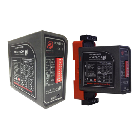
Nortech PD160 Enhanced Series User manual

Nortech International (Pty) Ltd
PO Box 4099 32A Wiganthorpe Road
Willowton Hub Pietermaritzburg
Pietermaritzburg 3201 South Africa
3200 South Africa Reg. No: 98/1095
Tel: (033) 345 3456 Int. Tel: +27 33 345 3456
Fax: (033) 394 6449 Int. Fax: +27 33 394 6449
Email: mkt@nortech.co.za URL: www.nortech.co.za
PD160 Enhanced Series
Inductive Loop Vehicle Detector
USER MANUAL
NORTECH INTERNATIONAL (PTY) LTD
All rights reserved
Copyright © 2011
Document Number: 304UM0001_00
Date of Issue: October 2011
This document is for information only and unless otherwise indicated, is not to form part of any contract. In accordance
with the manufacturer’s policy of continually updating and improving design, specifications contained herein are subject
to alteration without notice.

304UM0001 Rev 00 PD160 Enhanced Series User Manual Page: 2 of 39
Table of Contents
1.
INTRODUCTION........................................................................................................................................5
2.
TECHNICAL DATA ...................................................................................................................................6
2.1
Functional Data ......................................................................................................................................6
2.2
Electrical Data ........................................................................................................................................7
2.3
Environmental Data................................................................................................................................7
2.4
Mechanical Data.....................................................................................................................................8
2.5
Approvals................................................................................................................................................8
3.
OPERATING PROCEDURE......................................................................................................................9
3.1
Hardware Set-Up....................................................................................................................................9
3.2
LCD Menu System .................................................................................................................................9
3.2.1
Idle Display....................................................................................................................................10
3.2.2
Frequency .....................................................................................................................................10
3.2.2.1
Automatic Frequency Selection.................................................................................................11
3.2.3
Sensitivity ......................................................................................................................................12
3.2.3.1
Automatic Sensitivity Boost .......................................................................................................12
3.2.4
Presence .......................................................................................................................................13
3.2.5
Relay .............................................................................................................................................13
3.2.5.1
Relay Pulse Width .....................................................................................................................14
3.2.5.2
Relay Output Delay (Filter)........................................................................................................14
3.2.5.3
Output polarity ...........................................................................................................................15
3.2.6
Diagnostics....................................................................................................................................15
3.2.7
Reset.............................................................................................................................................17
3.2.7.1
Power fail...................................................................................................................................18
3.3
Front Panel Indicator ............................................................................................................................19
4.
PRINCIPAL OF OPERATION .................................................................................................................20
4.1
Detector Tuning....................................................................................................................................20
4.2
Detector Sensitivity...............................................................................................................................20
4.3
Types of Output....................................................................................................................................21
4.3.1
Presence Output...................................................................................................................................21
4.3.2
Pulse Output.........................................................................................................................................22
4.4
Response Times...................................................................................................................................22
5.
INSTALLATION GUIDE ..........................................................................................................................23
5.1
Product Safety Requirements...............................................................................................................23
5.2
Operational Constraints........................................................................................................................23
5.2.1
Environmental Factors to Consider...............................................................................................23
5.2.2
Crosstalk .......................................................................................................................................24
5.2.3
Reinforcing ....................................................................................................................................24
5.3
Loop and Feeder Material Specification...............................................................................................24
5.4
Sensing Loop Geometry.......................................................................................................................25
5.5
Loop Installation ...................................................................................................................................26
6.
CONFIGURATION...................................................................................................................................28
6.1
PD161 Enhanced Series Detector : English.........................................................................................28
6.2
PD162 Enhanced Series Detector : English.........................................................................................29
6.3
PD164 Enhanced Series Detector : English.........................................................................................29
7.
APPLICATIONS ......................................................................................................................................30

304UM0001 Rev 00 PD160 Enhanced Series User Manual Page: 3 of 39
8.
CUSTOMER FAULT ANALYSIS ............................................................................................................31
8.1
Fault Finding.........................................................................................................................................31
8.2
Detector On Board Diagnostics............................................................................................................32
8.3
Functional Test.....................................................................................................................................32
APPENDIX A - FCC ADVISORY STATEMENT ................................................................................................33
APPENDIX B – INSTALLATION OUTDOORS..................................................................................................34
Appendix B.1
IEC 60950-22:2005 – Outdoor cabinet..................................................................................34
Appendix B.2
IEC 60950-22:2005 - Northern Europe .................................................................................34
Appendix B.3
IEC 60950-1:2005 – Overvoltage Category..........................................................................34
APPENDIX C – REQUEST FOR TECHNICAL SUPPORT FORM....................................................................35

304UM0001 Rev 00 PD160 Enhanced Series User Manual Page: 4 of 39
WARNING: 1. This unit must be grounded (earthed) !
WARNING: 2. Disconnect power before working on this unit !
WARNING: 3. Installation and operation by service personnel only !
WARNING: 4. No user serviceable parts inside. No internal settings.
Warranty void if cover removed !
WARNING: 5. Always suspend traffic through the barrier area during
installation and testing that may result in unexpected
operation of the barrier.
WARNING: 6. USA
FCC Advisory Statement – Refer to Appendix A at the
end of this document.
WARNING: 7. Europe
Disposing of the product:
This electronic product is subject to
the EU Directive 2002/96/EC for
Waste Electrical and Electronic
Equipment (WEEE). As such, this
product must not be disposed of at
a local municipal waste collection
point. Please refer to local
regulations for directions on how to
dispose of this product in an
environmental friendly manner.

304UM0001 Rev 00 PD160 Enhanced Series User Manual Page: 5 of 39
1. INTRODUCTION
The PD160 Enhanced Series Single Channel Inductive Loop Vehicle Detector is a microprocessor
based detector designed specifically for parking and vehicle access control applications. It is suited
primarily to complex multilane access control and counting applications. Using the most up-to-date
technology, the PD160 has been designed in order to meet the requirements of a vast number of
parking applications (in terms of operating conditions and options available to the user).
The primary function of the detector is to detect vehicle presence by means of an inductance change
caused by the vehicle passing over a wire loop buried under the road surface.
The detector has been designed for ease of installation and convenience. With the on-board
diagnostics and automatic frequency selection to assist with installation, as well as customisable
outputs, the product is easily configurable to suit most applications.
With the introduction of the easy to operate LCD menu system, settings can be changed for
frequency, sensitivity, presence modes, as well as configurable and interchangeable output
combinations. The menu also provides access to a host of diagnostic and statistic information.
Over and above the LCD menu system, the PD160 provides additional visual outputs (LED’s) on the
front of the enclosure to provide an indication of the state of the channel as well as the detector itself.
The channel LED indicates whether a vehicle is present over the loop or there is a fault on the loop
while the power LED indicates that the unit has been powered and is operational or whether the
channel has recovered from a fault.
The unit has relay change-over contacts on the 11 pin connector at the rear of the enclosure, for
providing outputs as selected through the menu system.
Related Documents:
Data Sheet Document No. 304DS0001
Installation Leaflet Document No. 304LF0001
1 Channel Vehicle Detector Installation Guide Document No. 300LF0006

304UM0001 Rev 00 PD160 Enhanced Series User Manual Page: 6 of 39
2. TECHNICAL DATA
2.1 Functional Data
Tuning Fully Automatic
Self-tuning range 20 µH to 1500 µH
Sensitivity Fifteen step adjustable on the LCD menu
Ranging from 0.01% L/L to 5% L/L
ASB (Automatic Sensitivity Boost) selectable
Frequency Eight step adjustable on LCD menu
12 – 80 kHz (Frequency determined by loop geometry)
AFS (Automatic Frequency Selection) selectable
Output Configuration 2 output relays (3
rd
output optional)
User configurable for: Presence on detect or fault
Pulse on detect, un-detect, or fault
Normally Open (N/O) contacts
(Opto-Isolated outputs are available on request. MOQ applies)
Pulse Output Duration Eight step selectable on the LCD menu
Ranging from 50ms to 2seconds (Default set to 150ms)
Filter (Delay) Eight step selectable output filter
Ranging from 100ms to 10seconds (Default is OFF)
Presence Method Permanent or Limited to approximately 1 hour for a 1% L/L
Presence Time Eight step selectable on LCD menu
Ranging from 30seconds to 60minutes (Default is OFF)
Drift Compensation Rate Approx. 1 %∆L/L per minute
Response Times 100-200 milliseconds (subject to sensitivity level and level of detect,
as well as speed of vehicle over the loop)
Visual Indications 1 x Power / Status LED – Red
1 x Channel Status LED – Green
LCD diagnostics displays
Reset Selectable through the menu structure for:
Resetting Channel Statistics
Retuning Channel
Resetting settings to factory default
Surge protection Loop isolation transformer, gas discharge tubes,
and Zener diode clamping on loop input
Power Fail Selectable to have infinite memory retention of detector state on
power failure (provided certain criteria are met. Refer to section
3.2.7.1.

304UM0001 Rev 00 PD160 Enhanced Series User Manual Page: 7 of 39
2.2 Electrical Data
Power requirements 120 V
AC
± 10% (48 to 62Hz) (PD161)
230 V
AC
± 10% (48 to 62Hz) (PD162)
Requirement: 1.5 VA Maximum @ 230 V
12 V -10% to 24 V +10% DC/AC (48 to 62Hz) (PD164)
Requirement: 1 VA Maximum @ 12 V
Relay Contact Rating Relays rated – 1 A @ 230 V
AC
Optional – Opto Isolated 50mA @ 30V
DC
For ambient temperatures above 60°C De-rate the rel ay
maximum current as per graph below:
2.3 Environmental Data
Storage Temperature -40°C to +80°C
Operating Temperature -30°C to +70°C (as a funct ion of the LCD)
(below -20°C the LCD response time is affected)
Humidity Up to 95% relative humidity without condensation
Circuit protection Conformal coating over the PCB and all components
IP Rating IP30 – This product MUST be installed in an enclosure

304UM0001 Rev 00 PD160 Enhanced Series User Manual Page: 8 of 39
2.4 Mechanical Data
Housing Material ABS blend
Mounting Position Shelf or DIN rail mounting
Connections 11-pin Submagnal (JEDEC No. B11-88)
Size of Housing 78mm ( High ) X 41mm ( Wide ) X 80mm ( Deep )
2.5 Approvals
CE Regulations: EN 301 489-3 Equipment Type: III
Class of Equipment: 2
EN 50293 Performance Criteria B
Safety: IEC / EN 60950-1
80 mm
75.9 mm
77.7 mm
40.6 mm

304UM0001 Rev 00 PD160 Enhanced Series User Manual Page: 9 of 39
3. OPERATING PROCEDURE
3.1 Hardware Set-Up
The PD160 Enhanced Series single channel parking detector is designed to be shelf or DIN rail
mounted, with the controls and visual indicators at the front, and wiring at the rear of the enclosure.
The power, loop and relay outputs are all connected to the single 11-pin plug, which is mounted at the
rear of the enclosure.
3.2 LCD Menu System
Normal Display Frequency
Settings
Sensitivity
Settings
Presence
Settings
Relay Settings
Diagnostics
Reset Settings
Go back…

304UM0001 Rev 00 PD160 Enhanced Series User Manual Page: 10 of 39
3.2.1 Idle Display
The idle display is the normal display shown when not in the menu
system. It displays the model of the unit. Any button pressed will
enter the menu system. The up () and down () arrows are used to
navigate the system, while the enter button is used to select items,
e.g. changing settings, going deeper into the menu, or going back.
Under normal operating conditions, if a button is inadvertently
pressed, or during the use of the menu system, the menu will go back
one display every 25 seconds. This is not the case in the diagnostics
thus keeping certain desired information on display.
The menu system does NOT interfere with the operation of the unit; it merely provides the ability to
change settings and to view diagnostics. The unit is fully operational while menu settings are changed
and most settings have immediate effect.
3.2.2 Frequency
The frequency settings menu is the first menu and is used to shift the
operating frequency of the detector. This is primarily used to handle
situations in which more than one detector is used at the same site.
The detectors must be set-up to ensure no crosstalk (interference)
occurs between adjacent loops connected to different detectors. This
is achieved by ensuring that the loops of the two detectors are
spaced sufficiently apart (approximately 2 metres between adjacent
edges) and also ensuring that the detectors are set to different
frequencies.
The loops connected to multichannel detectors are not susceptible to crosstalk due to the design of the
loop interface. For more information about crosstalk refer to section 5.2.2.
The frequency setting allows the operating frequency of the loop to be shifted higher or lower
depending on the selection. However, the operating frequency of the detector channel is determined
by a combination of:
Inductance of the loop and feeder cable
Detector frequency settings
The operating frequency of the detector channel increases as the loop inductance decreases and vice
versa. The inductance of the loop and feeder cable is determined by:
Size of the loop
Number of turns in the loop
Length of feeder cable
As a general rule, the detector connected to the inductive loop with the greatest inductance should be
set to operate at the lowest frequency.
If the frequency reading from the on-board diagnostics is close to the maximum frequency, the
inductance of the loop is too low and more turns need to be added to the loop. However if the reading
is close to the minimum frequency, the inductance of the loop is too high and you need to remove
turns from the loop.
If the detector is operating close to either limit, it is possible that either the frequency drift caused by
environmental changes or the shift in frequency caused by a large %∆L/L detect will cause the
frequency to go outside the limits and cause a retune.

304UM0001 Rev 00 PD160 Enhanced Series User Manual Page: 11 of 39
Setting Offset
8 Highest 8%
7 6%
6 4%
5 2.5%
4 2%
3 1.5%
2 1%
1 Lowest 0%
AFS Automatic
End1
There are eight manual frequency shift selections to choose from,
numbered from 1 to 8, with 1 producing the lowest frequency and
8 the highest. The amount the frequency is shifted depends on
the inductance of the loop and feeder cable but is approximately
equivalent to the offset value shown in the table (where the value
shown is the percentage shift up in frequency from the lowest
setting). This amount decreases slightly for smaller inductances.
Due to the non-linear nature of the oscillator, the higher
selections produce more of a shift than the lower ones.
The eight settings allow a shift across the tuneable inductance
range of over 20%.
Selecting any one of these manual settings will put the detector into manual frequency selection and
retune the channel to that setting. At each extreme of high frequency and low frequency, there will be
some settings which don’t allow the channel to tune as the frequency shift could push the frequency
out of the acceptable operational range. It is possible for the operational frequency to be sufficiently
high or low that none of the selections are tuneable. In this situation, refer to the on-board diagnostics.
3.2.2.1 Automatic Frequency Selection
The PD160 Enhanced Series introduces the new Automatic Frequency Selection (AFS) which is
turned on by default. This setting allows the detector to briefly evaluate all eight frequency shifts and
select the best frequency offset available. It weighs up each selection based on where the frequency is
located within the operational range, the signal strength, and the level of detected noise. AFS allows
the detector to evaluate all the frequency selections where-as if it is deactivated, the detector only
evaluates the user selected frequency.
Due to the increased processing required, AFS takes longer to tune
than when it is deactivated. When AFS is activated, under the normal
or idle display, the display will indicate that it is attempting to tune.
The tune time with AFS on can range from 5 to 20 seconds. If after
this period of time, the detector still has not tuned, refer to the on-
board diagnostics as it is also possible that none of the frequency
selections are suitable. In this case the detector will indicate a fault
under the diagnostics displays.
Due to the sporadic nature of noise, the channel may seem quiet during the evaluation but still suffer
from cross-talk. There may be some extreme cases where the 20% shift in frequency is insufficient to
handle the amount of cross-talk.
For more information on cross-talk, refer to the installation guide at section 5, specifically section 5.2.2.
For more information about diagnostics, refer to section 3.2.6.
For more information about tuning refer to section 4.1.
AFS can be toggled on or off via the frequency menu. When activated, the channel will be retuned to
find the best frequency of operation. When deactivated, if the channel is tuned, it will not retune but
remain at the previously selected frequency. If deactivated while the detector is tuning, it defaults to
setting 5 of 8. In this situation, it is recommended that the user selects a frequency setting.
While the detector is tuning, it is recommended to allow the previous selection to complete.
On both manual and automatic frequency selection, once a valid frequency offset has been selected,
the detector waits for that setting to settle below the sensitivity setting before allowing normal operation
to continue. If there is sufficient drift from an extreme temperature change in the installation location or
vehicles driving over the loop at the time, it is possible that the tuning will timeout, invalidate that
frequency selection and attempt to tune again. The diagnostic displays will indicate drift in this

304UM0001 Rev 00 PD160 Enhanced Series User Manual Page: 12 of 39
situation. If the situation is very close to the limit, it is possible that it might tune as the
drift or noise goes back over the threshold and the unit goes into detect just as it
tunes. In a noisy environment, this can be prevented by retuning and if the situation persists to
decrease the channel sensitivity or increase the relay output delay.
The PD160 Detector can handle environmental conditions that cause the frequency to drift up at a rate
of approximately 1 %∆L/L per minute. Above this, false detects can occur.
If the drift is high it could be a possible fault with the loop or feeder cable. Possibly the wire insulation
has deteriorated and moisture is causing a short to earth or wires of the loop are no longer
encapsulated and are moving.
For more information about Frequency drift refer to the “Theory of Application” section in the
Diagnostic Unit DU100 User Manual Document No. 895UM0001.
3.2.3 Sensitivity
The sensitivity of the detector determines the change of inductance
necessary to produce a detect. The PD160 provides a much larger
range of sensitivities, with fifteen available settings.
Defined as the percentage change in inductance, the sensitivity
selections range from 0.01% which is the highest sensitivity, to 5.0%
as the lowest sensitivity.
Setting
0.01% Highest
0.02%
0.03%
0.04%
0.05%
0.06%
0.07%
0.08%
0.09%
0.10%
0.20%
0.50%
1.00%
2.00%
5.00% Lowest
ASB Automatic Sensitivity Boost
For a standard loop of 1.0 metres by 2.0 metres with 2 turns (circumference less than 10 m) and a ten
metre feeder cable the above right table shows typical sensitivity values for different vehicle types. For
more information about Sensitivity refer to the “Theory of Application” section in Diagnostic Unit
DU100 User Manual Document No. 895UM0001.
3.2.3.1 Automatic Sensitivity Boost
Automatic sensitivity boost (ASB) is a mode which alters the un-detect level of the detector, and can
be toggled on or off via the sensitivity menu.
ASB causes the sensitivity level to be boosted to a maximum on detection of a vehicle, irrespective of
current sensitivity level and maintained at this level during the entire presence of the vehicle over the
loop. When the vehicle leaves the loop and the detection is lost, the sensitivity level reverts to the pre-
selected level.
VEHICLE TYPE %∆L/L
Metal Supermarket Trolley
Bicycle 0.04
Motorbike 0.12
Articulated Truck 0.38
Four Wheel Drive 0.40
5 Ton Tip Truck 0.45
Motor Car > 1.00
Forklift > 1.00

304UM0001 Rev 00 PD160 Enhanced Series User Manual Page: 13 of 39
3.2.4 Presence
The presence setting determines how the detector handle detects.
There are two modes to choose from, namely permanent presence
and limited presence.
Permanent presence mode is aimed at maintaining the presence of a
vehicle over the loop by continuously compensating for all
environmental changes. This is used in situations where safety is
involved and the detector is required to maintain the detect.
Limited presence, however, is aimed at limiting the presence of a vehicle over the loop. This is used in
situations where statistics or control is involved and a vehicle parked over the loop should not prevent
continued operation. The presence is limited to approximately one hour for a 1% L/L.
The presence mode can be toggled between permanent and limited presence via the presence menu.
In addition to the mode selected, a time-out may be set which operates in both modes. The time-out
selections range from 0 (off) to 60 minutes. If limited presence is selected and a time-out is defined,
the first time to expire will release the detect, effectively tuning out the vehicle’s presence. In this way,
subsequent vehicles travelling over the loop may be processed.
Setting
0 sec (Off)
30 sec
1 min
4 min
10 min
20 min
40 min
60 min
Presence (Permanent or Limited)
3.2.5 Relay
The PD160 Enhanced Series provides user defineable outputs on each relay. The detector setup
allows for relay outputs to be generated in the event of a vehicle entering, being present on or exiting
the loop.
The relay menu allows for complete customisation of the outputs.
After selecting which relay to adjust, each relay output may be set to
any possible combination of presence event, or pulse event (i.e.
pulse on detect or un-detect), pulse duration and output delay. Only
once a final presence or pulse setting has been selected will the new
setting take effect.
Whether the relay is activated on presence or a pulse signal is selected, the delay time and fail-safe /
secure settings for the channel can also be adjusted. A detect is classified as the entry of a vehicle
onto the loop, where an un-detect is the exit of the vehicle from the loop.

304UM0001 Rev 00 PD160 Enhanced Series User Manual Page: 14 of 39
Setting
Presence Detect
Fault
Pulse Detect
Un-Detect
Fault
Pulse Width 50ms
150ms
250ms
500ms
750ms
900ms
1sec
2sec
Delay Output 0sec (off)
100ms
250ms
500ms
1second
2seconds
5seconds
10seconds
Polarity (fail safe / secure)
3.2.5.1 Relay Pulse Width
Under the pulse sub-section of the relay menu, pulse widths range
from 50ms to 2seconds and can be different on each relay.
Short pulses are used in responsive systems where higher speed
outputs can be individually processed, or limited to a shorter period of
time than the time the vehicle remains over the loop. Longer pulses
may be used where the output required is longer than the time the
vehicle remains over the loop.
3.2.5.2 Relay Output Delay (Filter)
From the relay menu, the delay time (filter) setting ranges from zero
(off) to 10 seconds and allows the output to be delayed accordingly.
By setting a non-zero delay, the output delay feature is turned on.
Small unwanted objects may be filtered out as a vehicle has to be
present over the loop for the full duration of the delay in order to
produce an output.
The delay time may be applied on any sensitivity level and may be different on each relay. It may also
be used on either presence or pulse output.

304UM0001 Rev 00 PD160 Enhanced Series User Manual Page: 15 of 39
3.2.5.3 Output polarity
The relay output polarity may be toggled between fail-safe and fail-secure via the relay menu.
In fail-safe, the output is the same in detect as it is with no power applied to the unit. Related to an
access control situation, this is used in situations where the loss of power must not lock people out.
Either a valid detect situation, or a power failure / fault will provide a signal.
In fail-secure, the output is the same in un-detect as it is with no power applied to the unit. Related to
an access control situation, this is used in situations where the loss of power must not allow people
free entry. Only a valid detect situation will provide a signal.
If installed correctly, the normally open contacts should be open in the event of no vehicle over the
loop and closed for a vehicle present over the loop. Units supplied with relays set to presence by
default are wired as fail-safe relays. Relays set to pulse by default are wired as fail-secure relays.
If the state of the output when the detector is off is not of concern, the polarity function can effectively
be used to flip the output logic on that relay.
3.2.6 Diagnostics
Users familiar with the DU100 from the PD130 range will find similar
features in the on-board diagnostics facility. The PD160 Enhanced
Series detectors are constantly monitoring their operation and
providing diagnostic information. Additionally, statistical information
such as the min and max values and the number of vehicles counted
are provided.
The following parameters may be verified using the diagnostics:
•Loop status – Display the actual loop operating frequency and magnitude of the current change of
loop inductance %∆L/L as well as signal and noise levels.
•Sensitivity – Display the minimum and maximum changes of inductance %∆L/L that caused a
detect since the statistics were last cleared.
•Channel counts – Display the number of vehicles detected.
This historical information is valuable for providing information about intermittent faults. It is highly
recommended that after installation of a detector (or if the loop has been changed in any way) that the
diagnostics is used to verify the correct operation of the detector. A record of the readings should be
kept so that if there is a problem in the future a comparison can be made to identify what has
changed. The form in Appendix C could be used to record these readings.
The sub-menus for diagnostics are as follows:
The frequency sub-menu shows the current frequency in kilohertz as
well as the individual max and min. The frequency is inversely
proportional to the inductance, so low inductances will show high
frequencies while high inductances will show low frequencies.
Depending on the frequency setting, the displayed values could be
from 12 to 80 kilohertz in the 20 to 1500uH range.
The sensitivity sub-menu shows the current percentage change in
inductance. Detects are shown as negative values and anti-detects
are shown as positive values. The max value will show the largest
percentage change noted while the min value will show the smallest
peak value of any one vehicle detected.

304UM0001 Rev 00 PD160 Enhanced Series User Manual Page: 16 of 39
The noise sub-menu shows the instantaneous noise measured over
a short period of time. Due to the sporadic nature of noise, it is
difficult to determine the difference between true noise and faster
moving vehicles which produce large detect levels. As such, the max
value may show a larger number as a function of some vehicle detect
properties. Simply reset the statistics and monitor the max without
vehicles passing over the loop to get a better indication.
The signal sub-menu shows the percentage of the maximum signal
strength able to be processed by the microprocessor. While the
signal should reflect 100% across the inductance range, it is normal
for it to start to drop slightly at very low inductances towards the edge
of the range. If the feeder cable is too long or the series resistance is
too high, the signal level will be seen to drop further. The detector
does not allow a loop to tune if the signal strength is below 35%.
The channel count sub-menu shows the number of vehicle detects as
a function of sensitivity and presence. It should be noted to prevent
confusion that this is NOT necessarily the same as the number of
relay output events, depending on your output settings. For example,
fault outputs would yield a different total output count from the
number of vehicles detected.
Where the current value is shown (as opposed to max and min) and the channel is in fault, the current
fault will be displayed. The possible fault displays are:
Short circuit The loop is showing short circuit properties. These include, but are not limited
to, very low signal level or very high frequency.
Open circuit The loop is showing open circuit properties. This is seen at very low
frequencies and in some cases at low signal level. From frequency shift
setting 5 and upwards, an open circuit does not oscillate and looks like a
short circuit. Manually select frequency 1 to confirm an open circuit condition.
Signal In trying to retune, the loop signal level was found to be too low to measure
reliably. This could be due to, but is not limited to, very low inductance or high
feeder cable resistance.
Noise In trying to retune, the detector found large movements determined to be
noise. This could be due to, but is not limited to, crosstalk from other loops or
vehicles driving over the loop during tuning.
Drift In trying to retune, the detector found unidirectional movements (either up or
down in frequency) which exceed the sensitivity. This could be due to start-up
conditions but is also noted at higher sensitivity levels at the extreme high and
low inductances.

304UM0001 Rev 00 PD160 Enhanced Series User Manual Page: 17 of 39
3.2.7 Reset
The reset menu is used for resetting detector values or functionality.
It also provides access to the way the detector responds to a
recovery from a loss of power in the powerfail setting.
The following sub-menu options are available:
The stats sub-menu is for clearing the statistical information of the
detector used in the diagnostics menu. This is basically the max and
min values as well as the channel counts and the recovered from
fault state. This can also be achieved by power cycling the unit.
The detector automatically tunes to the inductive loop connected to it
when the power is applied, whether on initial installation or after any
break in power supply. Should it be necessary to retune the detector,
the retune sub-menu provides the ability to re-initiate the automatic
tuning cycle. If there is a vehicle on the loop when a retune is
requested, it will be tuned out.
Every setting change done by the user is saved when the unit loses
power. For this reason, this Factory Reset sub-menu restores all the
settings to the factory defaults for the specific model after asking for
confirmation.

304UM0001 Rev 00 PD160 Enhanced Series User Manual Page: 18 of 39
3.2.7.1 Power fail
The powerfail setting may be toggled on and off via this selection in
the reset menu. Off by default, this setting is designed to retain the
memory of a vehicle on the loop in the event of a power fail situation.
This is designed specifically for fail-safe situations to retain the output
state and prevent a glitch on the outputs for a power failure. As such,
when the power is restored, the detector will not retune but return to
the detect state prior to the power failure. If a vehicle was on the loop
during the power failure, it will remain detected when the power is
restored. Thus it prevents the tuning out of a vehicle over the loop
during a power failure condition.
The memory retention of the vehicle is designed to be infinite, but is subject to the following limitations:
The level of the detect must be sufficiently greater (at least 0.5%) than the sensitivity level or
else the maximum potential temperature drift from one time of day when the power fails to
another when the power returns mustn’t exceed 20°C.
The level of the detect should be no less than 0.15% and a minimum of 0.15% above the
sensitivity level.
If the presence of a vehicle should occur less than a second before power is lost, there is a
chance that the unit won’t retain the detect and the outputs could toggle on restoration of
power.
If these conditions are not met, it is possible for the detect condition to be lost on recovery of power.
If Powerfail is used in conjunction with AFS and there is a concern of a channel going into fault, use
AFS to select the best band and then turn it off to prevent the unit retuning on recovery.

304UM0001 Rev 00 PD160 Enhanced Series User Manual Page: 19 of 39
3.3 Front Panel Indicator
The front panel indicators consist of a Red Power / Status LED and a Green Channel LED.
There are four possible conditions which are indicated by the LED’s.
•Idle condition – no vehicle is detected
•Detect condition – a vehicle is detected passing over the inductive loop
•Tuning condition – the detector is currently tuning to the loop
•Fault condition – the detector is unable to tune to the loop as it is either out of operational
conditions such as low signal strength or frequency out of range, or there exists a fault on the loop
such as a short circuit or an open circuit.
If a loop fault exists, the Green Channel LED will come on and flash at a rate of 2Hz indicating the
fault. If the fault is self-healing the detector will continue to operate but the LED will flash at a slower
rate of 1Hz indicating to the user that a fault has occurred. The detector must be power cycled or have
the statistics cleared in order to clear the historical fault information.
In order to distinguish between a detect condition and a tuning condition, the Channel LED displays
the same in tuning as it does in fault.
Once the channel is tuned, the Green Channel LED will go off. As indicated above, if the unit has
recovered from a fault, the channel LED will flash at 1Hz, otherwise it will remain off.
In the event of a vehicle being detected passing over the inductive loop, the Green Channel LED will
light up indicating the presence of a vehicle and remain on for the duration of the detected vehicle.
It should be noted, however, that the Channel LED does NOT necessarily represent the output state of
the relays. It only represents the detection of a vehicle over the loop. The relay state could for example
be different from the LED state in the case of a pulse output after its pulse duration, a fault output, or a
delayed (filtered) output. The only time the Channel LED will go off while a vehicle is still present is if a
presence time is set and has expired or if the channel is in limited presence mode and has expired.
The Red Power LED indicates that the unit is powered and functional. In the event of a fault recovery,
the Red Power LED will flash at the rate of 1Hz, out of sync with the channel LED, to indicate that the
channel has recovered from a fault. This is to provide visibility if the channel is in detect at the time of
viewing.

304UM0001 Rev 00 PD160 Enhanced Series User Manual Page: 20 of 39
4. PRINCIPAL OF OPERATION
The inductive loop vehicle detector senses the presence of a vehicle over an area defined by a loop of
two or more turns of wire, laid under the road or pavement surface. This loop of wire is connected to
the detector by a twisted pair of wires called a loop feeder.
A vehicle passing over a sensing loop causes a small reduction in the inductance of the loop, which is
sensed by the detector. The sensitivity of the detector is adjustable to accommodate a wide range of
vehicle types, as well as different loop and feeder combinations.
Upon detection of a vehicle passing over the loop the detector operates its output relays, which may
be used to indicate controls associated with the installation.
4.1 Detector Tuning
Tuning of the detector is fully automatic. The detector will re-tune if any of the following events occur:
- When power is applied to the detector
- A channel reset is initiated via the menu system.
- A detect of greater than 16% ∆L/L occurs.
- A fault has occurred and is self-healing.
The detector will automatically tune to any loop with an inductance in the range 20 to 1500 micro-
henries (H).
This wide range ensures that all loop sizes and feeder combinations will be accommodated in the
tuning range of the detector.
Once tuned, any slow environmental change in loop inductance is fed to a compensating circuit within
the detector, which keeps the detector correctly tuned.
For more information about tuning, noise and drift refer to section 3.2.2.1.
For more information about diagnostics, refer to section 3.2.6.
4.2 Detector Sensitivity
Sensitivity of the detection system is dependent on factors such as loop size, number of turns in the
loop, feeder length and the presence of metal reinforcing beneath the loop.
The nature of the application determines the required sensitivity, which may be adjusted by means of
the LCD Menu system on the front of the enclosure.
Table of contents
Other Nortech Security Sensor manuals
Popular Security Sensor manuals by other brands

Franke
Franke FAID0003 Installation and operating instructions

Profile
Profile 423000068 quick start guide

DSC
DSC COMMUNIQUE VPM4580 installation manual

Rawling
Rawling 59439 instruction manual

Det-Tronics
Det-Tronics X3301 instructions

Lippert
Lippert SolidStep Entry Assist Handrail Installation and owner's manual