895-87513.1
DETERMINING DETECTOR
CONFIGURATION AND
PROGRAMMING
To determine the current settings for the detector, click
on the “Configuration” tab. The Configuration window is
displayed (see Figures 6-7).
NOTE
Fields in the Configuration window that are
grayed-out are not eld selectable.
NOTE
If you would like to make changes to the detector’s
configuration, navigate to the setup tab and
change the Flame Inspector mode from Monitor
(default) to Congurator (See Figure 4 ).
IMPORTANT!
For flame detectors with EQP output, the EQP
controller will override any settings made with
Enhanced Flame Inspector (with the exception of
X3301 hangar mode).
To prevent this override, ame detectors with EQP
output should be changed in S3(see Instruction
Manual 95-8560 for details).
DETERMINING CURRENT
STATUS CONDITIONS
Click on the Device Status tab to determine the current
status of the detector. The status window (see Figures8 -
9) displays various status information about the detector.
For more information on detector status conditions refer
to the event log description and troubleshooting sections
of this manual.
NOTE
All information on this window is read only.
Indicators that are“grayed-out”are“Off”.
MANUAL
oi
TEST
Manual
oi
provides the same calibrated test as
automatic
oi
, and in addition, actuates the alarm relay to
verify proper operation. Manual
oi
can be performed at
any time and eliminates the need for testing with a non-
calibrated external test lamp.
The test can be initiated in one of three ways:
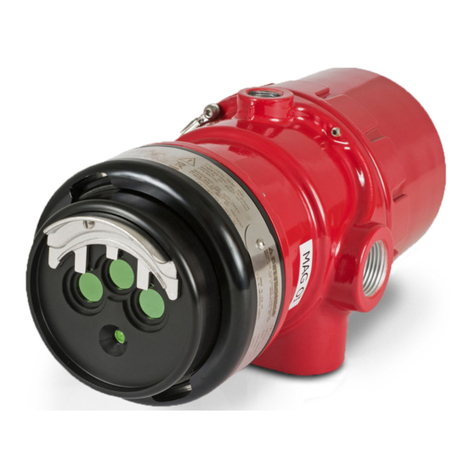
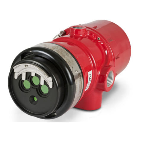
– by placing a magnet at the marked location (mag
oi
)
on the outside of the detector.
– via an external switch (refer to detector manual for
proper wiring).
– by Enhanced Flame Inspector software.
NOTE
If the sensor module is removed from the detector
housing for testing, only the Enhanced Inspector
method can be used.
MANUAL
oi
INITIATED BY MAGNET / SWITCH
CAUTION
Since the detector is fully operational, the test
requires disabling of all extinguishing devices to
avoid release resulting from a successful test.
Click on the Status button to display the Status window.
1. Initiate the manual
oi
test (actuate the external switch
or place the test magnet at the marked location on
the outside of the detector enclosure). The magnet
or switch must be held until the test is complete.
2. The Normal indicator on the Status window turns off.
3. Hold the switch or magnet for approximately 6
seconds. The manual
oi
test is successful if:
At the PC:
Fire Alarm indicator turns on (red).
Manual
oi
Active indicator turns on (red).
At the detector:
Fire Alarm Relay changes state.
LED turns red, exception: pulse output x-series
detectors.
4. Remove the magnet or release the test switch.
At the PC:
Fire Alarm indicator turns off.
Manual
oi
Active indicator turns off.
Normal indicator turns on (green).
At the detector:
Fire Alarm Relay returns to Normal condition.
LED turns green.
If the detector has successfully completed the test , the
fire extinguishing devices that were disabled for the test
can be returned to normal operation.
5. If the detector fails the test (i.e. less than half of the
detection range remains), no alarm is produced
and a fault is generated. A failed manual
oi
test is
indicated by:
At the PC:
Manual
oi
Active indicator turns off.
Manual
oi
Fault indicator turns on (amber).
