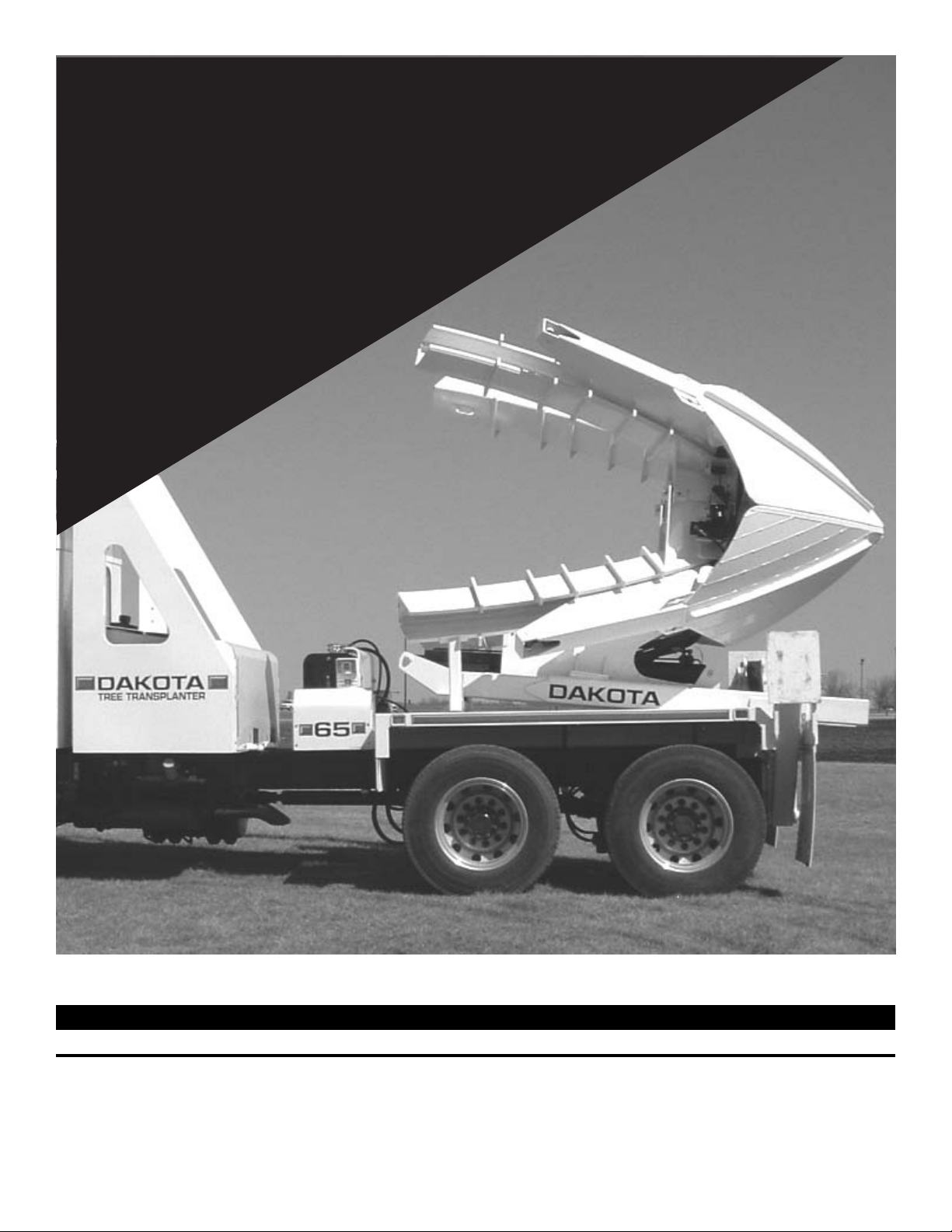
4
GENERAL INFORMATION
LABELING AND TERMINOLOGY
The Transplanter and this manual use the following terms
and symbols to bring attention to the presence of hazards of
various risk levels and important information concerning the
use and maintenance of the Transplanter.
WARNING: Indicates presence of a hazard which can
cause severe personal injury, death, or substantial property
damage if ignored.
CAUTION: Indicates presence of a hazard which will or
can cause minor personal injury or property damage if ignored.
NOTE: Indicates supplementary information worthy of
particular attention relating to installation, operation, or
maintenance of the Transplanter but is not related to a
hazardous condition.
Be sure to follow all instructions and related precautions
as they are meant for your safety and protection. This manual
is considered a permanent part of the Transplanter and must
remain with the Transplanter when sold.
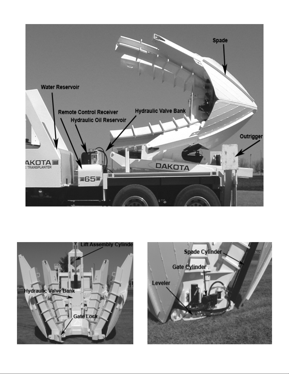
Record the model and serial numbers (found on the left
hand support) in the specifications section so they are readily
available when contacting a dealer for parts or service.
AUTHORIZED MAINTENANCE
Perform only the maintenance described in this manual
that you are qualified to perform. If major repairs are ever
needed or assistance is desired, contact an Authorized
DAKOTA Dealer for their professional service.
POWER OFF MAINTENANCE AND
ADJUSTMENTS
All maintenance and adjustments to the Transplanter must
be made with the transplanter in a secure position and the
truck’s parking brakes set, engine off, and key removed.
Failure to do so could result in injury or even death.
MAINTAIN SAFE OPERATING CONDITIONS
Grease all fittings as described in this manual. Proper
lubrication is essential for the safe operation and longevity
of the Transplanter.
Daily, visually inspect the Transplanter for any
abnormalities. Look for loose or broken hardware; bent or
damaged components; broken or fatigued welds; leaking,
worn or damaged hydraulic hoses and fittings.
RELIEVE HYDRAULIC PRESSURE
Before performing any work on the hydraulic system, all
pressure in the system must be relieved. Place the Transplanter
either in the transport position or firmly support the area being
serviced. Make sure all parts of the Transplanter actuated by
hydraulic pressure are supported or otherwise restrained to
prevent movement prior to relieving hydraulic pressure.
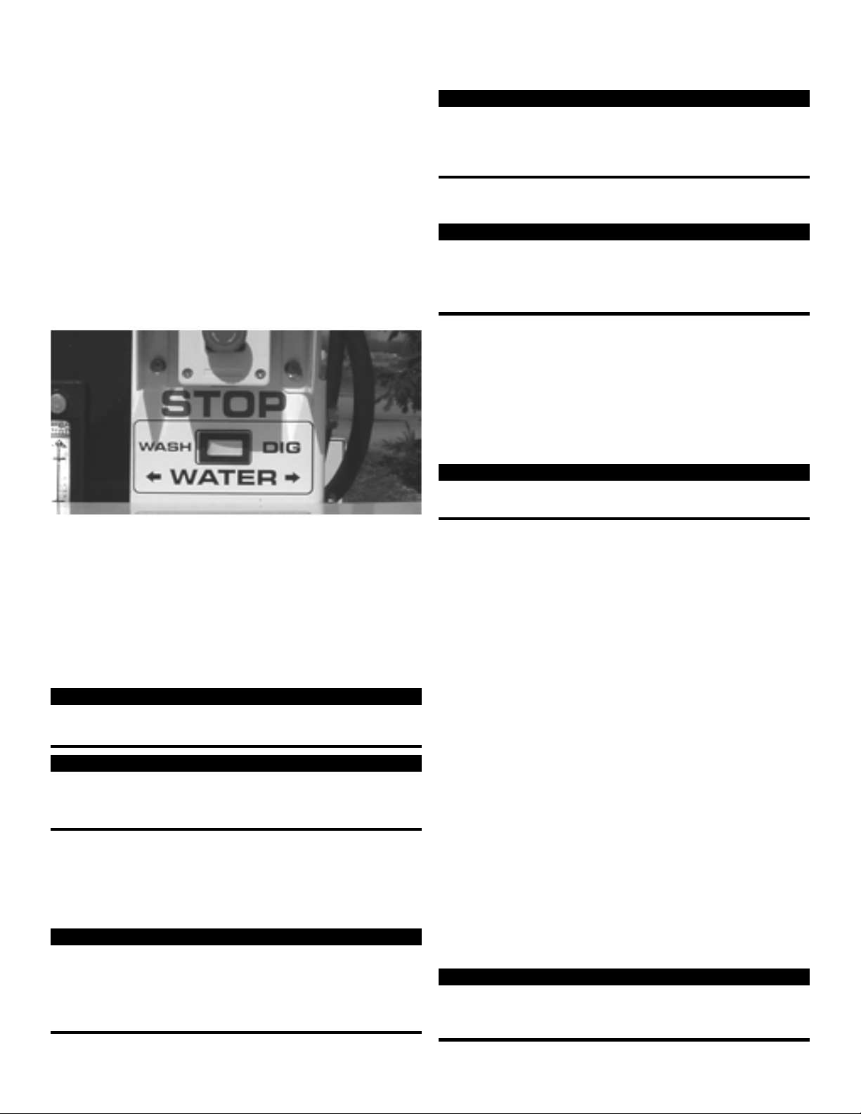
Disengage the power take off; then turn off the transmitter
and stop the truck engine. Using the special 1/2 in. wrench
found in the manual canister, rotate the hex shaft of the
appropriate valve to both ON positions. Residual hydraulic
pressure may still be present, so care must be taken. Failure
to do so could result in damage, injury, or even death.
KEEP TRANSPLANTER CLEAN
Keep the Transplanter free of excessive grass, leaves, and
accumulations of dirt and sand. Materials such as this can
compromise seals, bearings, and other components.
REPLACEMENT PARTS
To ensure optimum performance and safety, always
purchase genuine DAKOTA replacement parts and
accessories. NEVER USE “WILL-FIT” REPLACEMENT
PARTS AND ACCESSORIES MADE BY OTHER
MANUFACTURERS. Using unapproved replacement parts
and accessories voids the warranty of the DAKOTA
Transplanter. Right and left-hand sides are determined by
sitting in the driver’s seat of the truck.
If ever in need of a new remote, please provide DAKOTA
the serial number of either the existing remote or receiver to
ensure proper programming.
READ OPERATOR’S MANUALS
Prior to operating the Transplanter, read and understand
the contents of this Operator’s Manual and the Operator’s
manual of truck. Become familiar with all control functions
and know how to operate the truck and Transplanter safely.
Replacement Manual
A replacement manual is available by sending complete
Model and Serial Numbers to
Dakota, Inc.
833 Gateway Drive, North East
East Grand Forks, Minnesota 56721
UNAUTHORIZED OPERATORS
Never allow children to operate the Transplanter. Do not
allow anyone to operate the Transplanter without proper
instruction or training. Only trained and authorized persons
should operate the Transplanter.
DRUGS AND ALCOHOL
Never operate the Transplanter when under the influence
of drugs or alcohol.
SHIELDS AND SAFETY DEVICES
Keep all shields, guards, and safety devices in place. If a
shield, guard, or safety device is damaged, replace or repair
it prior to operating the Transplanter. If a decal is illegible,
order and install a new one.
LOOSE FASTENERS AND FITTINGS
Although the Transplanter has been designed so that
components will not come loose during normal operation of
the Transplanter, always check the Transplanter prior to start
up and after each use for loose fasteners, fittings, connectors,
and other components. Tighten, repair, or replace as necessary.
This includes electrical and hydraulic system components,
also.
MODIFICATIONS TO TRANSPLANTER
Do not modify the Transplanter in any way. Modifying
the Transplanter will void the warranty.