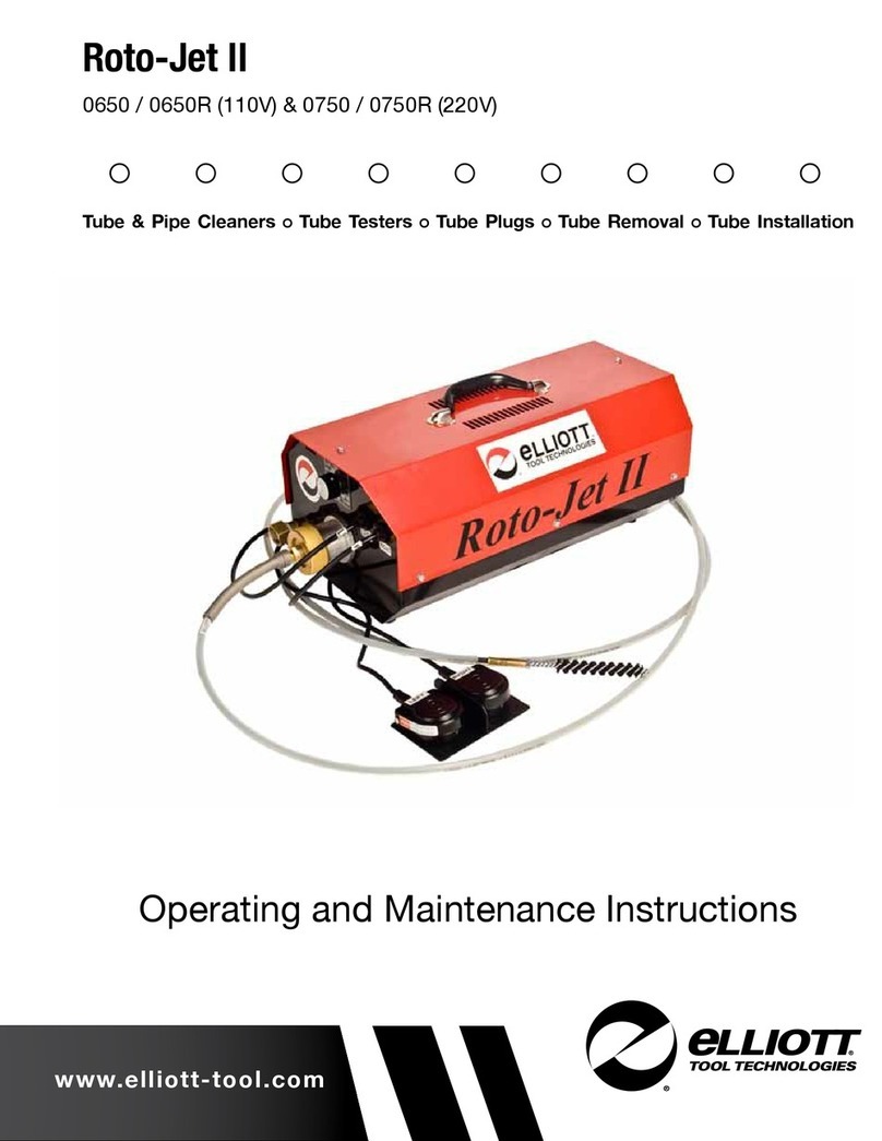
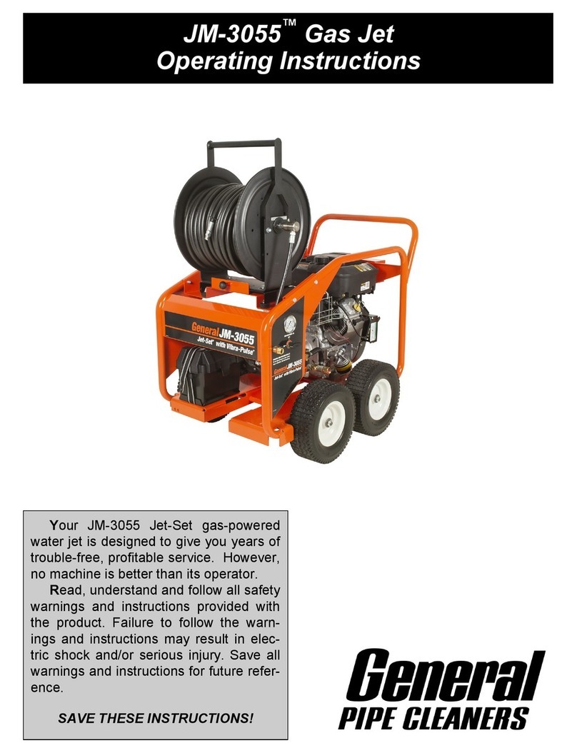
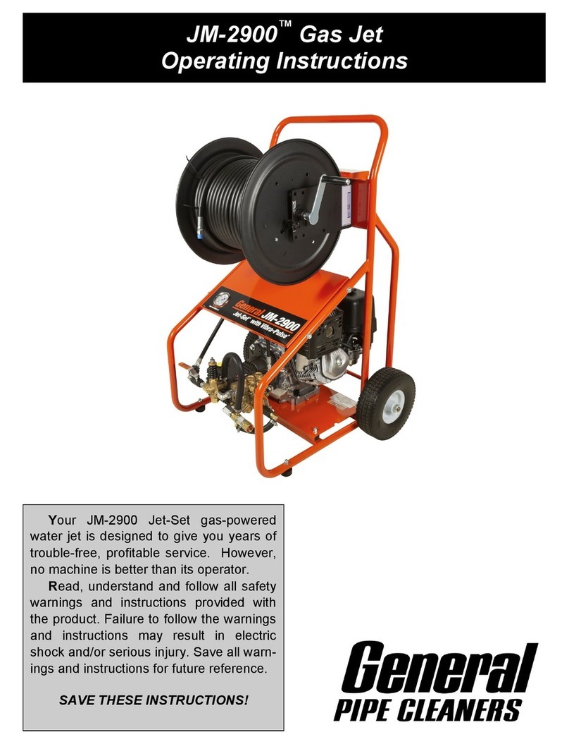
Dali GQ-75 User manual

1*si|

TABLE
OF
CONTENTS
Brief
Introduction
1
Application
Scope end Operation
Capability
2
Major
Component
Description
and Operating Characteristics
3-4
Operation Methods 5
Special
Soft
Shaft and Accessory 6
Special
Drill
6
Accessory Specification 7
Sectioned Machine Drawings
and
Parts Description
8-11
Maintenance
and
After -
Sen/ice
12
Safe Operation
13-15
Problems
and
Solutions
16
•
User
Feedback
Form
17

GO-75
No.
2.2011
GO
-100
No,
2,2012
GQ-150
No.
2,
2013
GO
-200
No,
2,2014
BRIEF
INTRODUCTION
Type GQ
-75
• Applicable for indoor pipelines of
<D20
~100mm in diame
ter, up to 30m in extension length.
•
Light,
strong, fast, easy to operate. Can be connected
with soft
shafts
of
(l>8
and<t'16.
Type GQ
-100
•
Applicable
for
indoor pipelines of
032
~100mm in diame
ter, up to 30m in extension length.
• Compactstructureand
lightweight,
Easy
to operate and
save
manpower.
Type GQ
-150
• Applicable for indoor pipelines of
cl>20
~150mm in diame
ter, up to 30m in extension length.
•
Multifunction
and high power with wide applications. Can
be
connected
with soft
shafts
of
08
,
016
and
022.
Type GQ -
200
•
Applicable
for
outdoor pipelines ofO50 ~200mm in diam
eter, up to
50m
in extension length.
• Preferable for operation of
multifunction
and heavy duty.
The machine and the flexible shaft
are
all equipped with
walking
wheels.
Easy
to operate and save manpower.

APPLICATION
SCOPE
AND
OPERATION
CAPABILITY
GQ-75
GQ-100
GQ-150
GQ-200
Indoor Pipeline •••
Outdoor Pipeline • •
Applicable diameter.
(<Dmml
20-100
32-100
20-150
50-200
Ext.
Length
Im)
30
30
30
50
8x5
15x2.5
16x2.5
8x5
Soft
Shaft Spec.
lOmm
xml
16x2.5
15x2.5
16x2.5
22
X 5
30x5
Rated Voltage
1
~V)
230
230
230
230
Rated Frequency
(Hz)
50
50
50
50
Input
Power
(W)
390
390
390
1100
Rotate
speed
(r. p. ml
400
400
400
700
Protection
Class
IP44
IP44 IP44
IP44
Noise
(dBiA)
I
^75
^75
^75
^75
Machine Mass 1kg)
27.3
20.9
43.54
77.
56

MAJOR
COMPONENT
DESCRIPTION
AND
OPERATING
CHARACTERISTICS
Stanby
Woildng
•k
J^iuuauaj
Control
Knob
For switching
on/off
circuit
and
controiiing rotation direction of
output shaft.
OFF
:Stop
FOR :
forward
rotation
REV ;
reversed
rotation
* Warning: Prior to connecting electric power supply check switch
firstfor position off.
Operate Control Handle
Press the
handle
to move
the
machine
clutch, which
makes
the
flexible
shaft
to
rotate.
Releasing the handle stops the
flexible
shaft rotation immediately.
* Warning: The pressing force shall not exceed 20kg, preferably to
the extent of locking the flexible shaft. Do not
use
force multipli
cation
tool.
Initial
state is"standby". Cog down state is"working'

MAJOR
COMPONENT
DESCRIPTION
AND
OPERATING
CHARACTERISTICS
%
4/
•'
Locking
screw
For
connecting
the
machine
with
08
flexible
shaft attachment and
protective
sleeve.
Raise
and
insert
the screw.
It
is simpleand
fast.
Note:
For
machines
GQ-100
and
GQ-150
removethe
white
sleeve
from
the
machine
tail first.
*Warning:
Switch
off
the machine beforeinstalling
flexible
shaft,
protectivesleeve or attachments.
Sleeve pipe
Use it for protect manipulator against
revolving
spring shaft.
WARNING'
Musi place ttie
guandpipe *Nomeplate ofogoinsthurthond.
Connect
the
soft
shaft
with drills
Push
the
drill
along
67°slider
slot
of the shaft to engage.
This
mokes
connection more reliable,easy and fast.
Caution: Observethrough the holeof the
drill
to see the pop-out
ofthe
flexible
shoftpin.
It
Is
onlysafe whenthe pin is out.
Remove
the
soft
shaft
Insert
the
key
and push the shaft
with
both hands in direction
opposite
to the T
slot
ofthe
terminal
to
remove
the
shaft.
It
saves
time and manpower.

OPERATION
METHODS
1.
Insert
the soft shaft
through
the 2.
Select
on oppropriote
drill
ond se-
mochine
shaft.
curely
connect
ittothe
soft
shaft.
3,
Put
the
machine
to a
suitable
position! do not touch waste wo-
ter) with
the
drill
and
the
flexible
shaft inserting info the pipeline
as
much as possible.
I
.|~
t*-
Keep
one segment (200 - 300mmI
of
the
soft
shaft
between
the
ma
chine and the pipeline opening.
Press
the
control
knob
and
hold
the
rotating
soft shaft and push it into
the
pipeline.
Repeat the above ac
tions
until
the
pipeline
is through.
4.
Let
the soft shaft be 2 - 4 m out of 5. Insertthe plug intoa well ground- 6.
Turn
on the
control
knob and let
the machine
tall.
Remove
the rest ed 3 - hole single phase
socket.
the machine shaft rotate
clockwise,
of
the
shaft
and
cover
it with a
protectionsleeve for future use.
8.
After
shutting down the machine
pull
9.
After
using machine let it free ro-
the soft shaft out of the pipeline.
Remove the
waste
and
clean it dry.
Keep it for future use.
Caution: Avoid the soft shaft bringing
the
waste
water
into
the
machine
or
contaminate
the
focilities
indoors.
tote for
2-3
minutes. Inject the
lubrication oil into oil holes. Keep
the machines at a dry place for
future
uses.

SPECIAL
SOFT
SHAFT
AND
ACCESSORY
OS
soft
shaft
Combination
Used for machines of GO - 75 and GQ-
ISO.
The length of
the shaft is 5m. Itcon be used in pipes of 20 - 50mm in di-
ometer.with
reverse
water
bend.
nurrymM
laswuMAU
Sectional
elastic
soft
shaft
Flexible
soft
shoft
Acombination of flexible shoft
and
drill.with igh strength
and
good flexibility.suitablefor pipes of small diameter or with re
verse
water
bend.
Enhanced strong soft shaft
Made
with
high
quQlily
springwires.assure
sufficient
mechan- A shaft made in
heavy
load and
with
intensive
wires.
En-
ical
strength
and
flexibility,
as
well
as
bending
resistance,
j
hanced
mechanical
strength
and
twisting
resistance,
suitable
twisting
resistance and
ductility
resistance. Itcon be
connect-
| for
complicoted
working
environment,
ed for any length.
Soft
Shaft
Holder
For
keepingand storing
flexible
shafts.
Protection
tube
To ovoid personal injuries from rotating ftexible shoft
and
as
sure
personal safety.
SPECIAL
DRILL
-
UNIQUE,
NEW
AND
DURABLE
iiinnntiMe
straight
helical
drill
Olive-shaped
helicol
drill
Flexible
olive-shaped
helical
drill
For
exploring
the pipe ofthe
blockage
end
For
guiding
the
flexible
shaft
through
the
For
pipes that are hard to
drill.
Good
ofthe
position
to
drill,
usually
used in the
complicoted
path and
drilling
though
the
flexibility
and
optimal
guiding
function,
first
step.
blocked
position.
Best
for
its
guide
function
Funnel
- shaped
helical
drill
Collection
helical
drill
4 - edge saw cutter
High
strength.
Usedinthe second step, to
effectively
re-
For
collecting
the
broken
flexible
shoft
or Used
for
removing
hard
materials
like
move the
blockage
residue
left
on the
drill
in the
pipe.
chemicol
deposits,
pipe wall by straight helical drilling.
Spade- shaped
cutter
Helical
saw
cutter
C- shaped
cutter
IUsed to remove the cream on the pipe
For
removing
blockage
like
roots, branch- ;
For
removing
moteriols
like
cream, soap
wall or used in the second step to remove es, debris or creams from pipe. etc which adhere to the pipe wall,
residues
onthe
pipe
wall.
I

ACCESSORY
SPECIFICATION
Cotalg No. Type Accessory Description
Unit
Spec. Applicotion type
mm
xm
GQ-75
GQ-100
GQ-150
GQ-200
2.0321
F-2-a1
<I>8
soft shaft combination
set
08x5
•
2.0322
F-2-b;
08
soft
shaft
combination
set
08
x5
•
2.
0131
R-3-1
Sectional flexible soft shaft
rod
Ol5x2.5
••
2.
0141
R-4-1
Sectional elastic soft shaft
rod
016x2.5
•••
2.
0142
R-4-2
Sectional elastic soft shaft
rod
022
x5
i •
2.
0143
R-4-3
Segment
elasic
shaft
rod
030
x5
t•
2. 0211
T-1
-a
Straight
helical
drill
piece
016
• 1 ••
2.
0212
T-l-b
Straight
helical
drill
piece
022
•
2.
0213
T-l-c
Straight
helical
drill
piece
O30
;•
2.
0221
T-2-a
Olive
- shaped
helical
drill
piece
016
•
2.0231
T-3-a
Rexible
dive
-shoped
helicol
drill
piece
016
••
2.
0242
T-4-b
Funnel
- shaped
helical
drill
piece
022
•
2.
0243
T-4-C
Funnel
- shaped
helical
drill
piece
O30
•
2.
0251
T-5-a
Collection helical drill piece
016
.••
2.
0253
T- 5- c i
Collection
helicol
drill
piece
O30
•
2.
0261
T-6-a
4-edge
sow
cutter
piece
016
•••
2.0262
T-6-b
4 - edge sow
cutter
piece
022
•
2.
0271
T-7-a
Spade-shaped
cutter
piece
016
••
2.
0272
T-7-b
Spade-shaped
cutter
piece
022
•
2.0273
T-7-C
Spade-shaped
cutter
piece
O30
1•
2.
0281
1-8-0
Helical
saw
cutter piece
016
1
•
2.
0283
T-8-C
Helical
saw
cutter piece
O30
'•
2.0291
T-9-a
C-shaped
cutter
^
piece
016
•
2.
0293
T-9-C
C-shaped
cutter
1
piece
O30
i
1•
2.
0315
F-l-e
Soft shaft holder piece
O360
•
2.
0316
F-l-f
Soft
shaft
holder
piece
O430
••
2.
0317
F-l-g
Soft shaft holder j
piece
0500
•
2.
0331
F-3-a
Key
' piece
04
•1 • •
2.
0332
F-3-b
Key
piece
06
1 1
- . i •
2.
0341
F-4-g
1
Stand
piece ii•1 .
2.
0351
F-5-a
Protection
gloves
piece ••••
2.0361
F-6-a
Accessory
barrel
piece •• :
!
2.
0371
F-7-a
Protection
tube
set
j
032
•
1 ^ ••
2.
0372
F-7-b
Protection
tube
set
042
•
2.
0391
F-9-a
Drill
shelves 1
piece
•

Sectioned
Machine
Drawings
and
Parts
Description
CQ
-75
pipe cleaner
GQ-75
SPECIFY
ACTION
Rtl
No:
Name
Model
No:
Quantity
Rtl
No:
Name
Model
No:
Quantity
1
Screw
Ml
0*25
2
22
Cack and pinionhousing 1
2
Flat
washer
010
2
23
Cap
05*5
plastic 1
3
Axle
1
24
Screw
M6*25
2
4Flat
key
4*18
1
25
Retaining ring
12
1
5
Cap
05*5
plastic
1
26
Washer
O30
1
6
Casing
1
27
Spring 1
7
Bush
1
28
Handle
grip
026*86
plastic
1
8
Post
1
29
Handle
with pinion 1
9
Washer
Assembly
10
Fixing
blocks
30
Pin
11
Bevel
gear
0105*24
PA6
1
31
Juncting
box
96*95*53
plastic
1
12
Pinion
gear
1
32
Capacity
10A/400V
plastic
1
13
Bearing
8205
1
33
Switch
lOuf/400v
1
14
Insulatingmotor gasket
O140
PVC
1
34
Rubber
feet
032*36
mbber
3
15
Flat
key
4*20
1
35
Screw
M4*12
4
16
Motor
250W/230V
1
36
Earth
lead
04
1
17
Strain
relies
Ml6
plastic 1
37
Spring
washer
04
1
18
Mains
cable
0.75'
/250v
rubber
1
38
Screw
M4*10
1
19
Axle
1
39
Name
plate
90*45
1
20
Bearing
8205
1
40
Spring
support
1
21
Gear
rack
1
41
Sign
26*40
PVC
1

CQ
-100
pipe
cleaner
\
GQ
-100
SPECm
ACTION
y V
o
Sectioned
Machine
Drawings
and
Parts
Description
1^:,.
//
Rtl
No:
Name
Model
No:
Quantity
Rtl
No:
Name
Model
No:
Quantity
1
bush
2
36
Washer
03
1
2Body
casting
1
37
Screw
M3*10
2
3
Screw
M10*16
4
38
Connecting
rod 4
4
Rubber
feet
<l)30*45mm
ABS
4
39
Screw
M8*16
2
5
stand
2
40
Pin
8*20
2
6
Washer
010
4
41
Washer
<1>8
2
7Oil
cup
06
2
42
Spring
washer
08
2
8
Protective
shield
040*68
PA6
1
43
Hexagonal
nut
M8
2
9
Strain
relies
Ml 6 plastic 1
44
Pin
04*25
2
10
Screw
M8*20
4
45
Handle
assembly
1
11
Screw
M6*20
2
46
Handle
grip
026*86
plastic
1
12
Spring
washer
06
2
47
Conducting
wire
0.75mm
21
13
Washer
06
2
48
motor
250W/230V
1
14
Support
1
49
Flat
key
4*20
1
15
Handle
135*72*20mm
ABS
1
50
Pulley
O3r30mm
PA6
1
16
Mains
cable
0.752
/250v
rubber
1
51
Shaft
1
17
Pad
130*20*11mm
PA6
2
52
Flat
key
4*14
1
18
Bolt
M6*20
4
53
belt
2*71*20
rubber
1
19
Washer
06
4
54
Pulley
0114*25mm
PA6
1
20
Spring
washer
06
4
55
Hood
050*16
ABS
1
21
Hexagonal
nut
M6
4
56
bearing
8205
1
22
Cover
330*260*49mm
ABS
2
57
Fixing
blocks
1
23
Screw
M4*10
8
58
Spring
24
Ring
023*14mm
rubber
1
59
Shaft
1
25
Name
plate
90*40
1
60
Spring
washer
26
Screw
M4*10
1
61
Adjusting
nut
1
27
Spring
washer
04
1
62
Adjusting
washer
1
28
Washer
04
1
63
Protective
shield
58*58*049mm
PA6
1
29
Earth
lead
04
1
64
Insertion
58*58*1.5mm
rubber
1
30
Screw
M6*10
1
65
guard
58*58*35mm
plastic
1
31
Washer
06
1
66
screw
M4*10
32
Guard
1
67
switch
10A/400V
1
33
Spring
support
1
68
Strain
rtlies
M12
plastic
34
Capacity
10uf/400v
1
69
box
60*50*60plastic1 1
35
Rxed
wire
reel
04
clastic
2
70
sian
26*40
PVC
1

Sectioned
Machine
Drawings
and
Parts
Description
CQ-150
pipe cleaner
11—^ .
69-^
GQ-150
SPECITY
ACTION
10
Rtl
No;
Name
Model
No:
i
Quantity
Rtl
No:
1
Name
Model No: _
Quantity
1
bush
1
36
Spring
1
2
Body
casting
11
37
Washer
O30
3
Screw
M10*16
4
38
Retaining
ring
012
1
4
Washer
O10
4
39
Spring
support
1
5
Elevator
bracket
2
40
Capacity
10uf/400v
1
6
Rubber
feet
<I)30*45mm
ABS
4
41
Fixed
wire
reel
04
plastic 2
7Protective shield i
074*50
plastic I1
42
Washer
03
2
8
Pin
1
43
Screw
M3*10
2
9Spring '1i
44
Screw
M6*35
4
10
Washer
010
11
45
Spring
washer
06
4
11
Hexagonal
nut
M10
1
46
Hexagonal
nut
4
12
Handle
|l35*72*20mm
ABS
1
47
Fixing
blocks
1
13
1
Support
11
48
Shaft
1
14
Screw
M6*20 ! 249 1
Bearing
8206
15
Spring
washer
i06
1
50
Gear
rack
1
16
Washer
06
1
51
Pulley 1
17
Screw
M6*12 i4
52
Bearing
8206
1
18
Rubber
plug
020*14
rubber
4
53
Hollow
shafe
•j
19
Strain
relies
jM16 plastic 1
54
Set
screw
M5*12
20
Mains
cable
0.75V
250v
rubber
i1
55
Screw
M5*12
1
21
Conducting
wire
0.75mm'
11
56
Pulley
4*20
22
Cover
2
57
Flat
key
1
23
Screw
M5*25
4
58
Motor
250W/230V
1
24
box
65*50*60
plastic
8
59
Pad
140*20*18
PA6
2
25
Protective
shield
58*58*049
PA6
1
60
Screw
M6*25
4
26
Insertion
158*58*
1.5mm
rubber
1
61
Washer
OS
4
27
Guard
|58*58*35mm plastic 1
62
Hexagonal
nut
4
28
Screw
M4*10
4
63
Adjusting
packing
014*10
rubber
2
29
Strain
relies
|M12 plastic 4
64
Screw
M4*10
1
30
Switch
10A/400V
plastic
1
65
Spring
washer
04
1
31
Guard
130*80
ABS
1
66
Earth
lead
04
1
1
32
Handle
grip
|026*86
plastic 1
67
Screw
M5*40
4
33
Handle
assembly
1
68
Name
plate
L202
rubber
1
34
Set
screw
iM8*10 1i
69
Belt
1 1
35
Gear
shafe
1
70
Sion
126*40
PVC
' 1

Sectioned
Machine
Drawings
and
Parts
Description
CQ -
200
pipe cleaner
Grounding
GQ-200
SPECITY ACTION
Rtl
No:
Name
Model
No:
Quantity
Rtl
No:
Name
Model
No:
Quantity
1
Hull
1
36
Strain
relies
M12 plastic 4
2
Screw
M5*35
2
37
Portative
shield
74*74*069
PA6
1
3
Gland
1
38
Insertion
74*74*1.5mm
rubber
1
4
Screw
M6*50
2
39
Guard
74*74*40mm
plastic
1
5
Screw
M6*30
2
40
Switch
10A/400V
1
6
brakes
3
41
Conducting
wire 1.0^ plastic 1
7
Belt
0 -
528
rubber
1
42
Stay
8
Washer
<D6 3
43
Anchor
plate
1
9
Rocker
arm
set
3
44
Screw
Ml
0*30
10
Pin
«P6*45
3
45
Awt
M10
1
11
Pin
<I>2*16 3
46
Bolt
Ml
0*45
1
12
Support
3
47
Motor
750W/230V
1
13
Screw
M5*8
3
48
Fiat
key
8*30
1
14
Spring
3
49
Pulley 1
15
Damper
1
50
Damper
1
16
Driving
shafe
1
51
Screw
M5*103
3
17
Clutch
cone
1
52
Washer
O10
4
18
Bearing
8112
1
53
Spring
washer
O10
4
19
Cam
1
54
Screw
Ml
0*20
4
20
Handle
1
55
Fixed
wire
reel
4
21
Ball
(I>40
plastic
1
56
Aut
M10
4
22
Plate
assembly
1
57
Spring
washer
O10
4
23
Screw
M8*30
3
58
Support
2
24
Jockey
pulley 2
59
Wheel
70kg 8" 2
25
Pin
8*30
2
60
Ring 2
26
Sleeve
pipe
050*185
plastic
1
61
Aut
M12
2
27
Yoke
1
62
Stand
1
28
Casing
1
63
Rubber
feet
2
29
Bail bearing
208
1
64
Screw
M5*10
1
30
Bearing
end
cover
086*35
BMC
1
65
Spring
washer
05
1
31
Screw
M8*30
1
66
Earth
lead
05
1
32
Guide
hose
pin
67
Sign
26*40PVC
33
Strain
reiies
Ml6
plastic
1
68
Sign
42*28PVC
34
Mains
cabie
1.0*/250v
rubber
1
69
Sign
35*35PVC
35
Name
olate
90*45
1
11

12
MAINTENANCE
AND
AFTER
-SERVICE
Keep
the
machine
well
lubricated.
Inject
the
lubrication
oil
(20#and 30#
oil)
Into
oil
holes
before
and aftereach use.
It
is
highly
recommended, when
finishing
the
operation,
that
you
lubricate the machine after
2-3
minute free rotation and keep it at a dry place.
Keep
the
electric
part
ofthe
machine
from
getting
wet.
It
Is
prohibited
to
operate
the
machine
In
water.
If
a
small
amountofthe waste water
accidentally
getting
Into
the
machine,
open the
machine cover Immediately and clear the water.
When the Insulation resistance of the machine Is less than 2Mfi, It Indicates the machine Is
wet.
To
assure
personal
safety
and
prevent
the
machine
from
damage, stop
operating
the
machine
and
put
It
at a
place
dry
and
ventilated
until
the
Insulation
resistance
restored
to
more
than
2AAft.
Prior
tothe
next
use
after
long
time
storage,
check
the
machine
for
free
rotation,
then
turn
on
the
control
switch.
If
the machine shaft does not rotate after the motor Is
running
or the handle
Is
pressed,
It
Indicates
the
machine
rusted
Inside.
Turn
off
the
electric
power
Immediately
to
ovoid
the
electric
damage.
Reoperate
the
machine
only
after
a
self
-
check
oron
Inspection
by
on
authorized
dealer
Is
done.
After
finishing
use
of
the
flexible
shaft
and
drills,flush
and
dry
them
clean.
Lubricate
them
with
oil and keep them at a dry place to prevent rusting.
Warning: Shut down the machine and disconnect the electric power before making any
adjustment,
accessory
assembly
and
maintenance.
Warning: Use approved rated power supply and less - than
-10A
fuse.

SAFE
OPERATION
1. Keeps work
area
clear
Cluttered
area and bencties
invite
injuries.
2.
Consider
work
area
environment
Do not
expose
tools to rain.
Do
not
use
tools
in
dam
or
wet
locations.
Keeps work
area
well
lit.
Do
not use tools inthe presence offlammable
liquids
or gases.
3. Guard against electric shock
Avoid
body contact
with
earthed or grounded surfaces (e. g. pipes, radiators, ranges,
and refrigerators).
4. Keep other persons away
Do not let persons, especially children, not
involved
in the work touch the tool or the ex
tension cord and keep them away
from
the work area.
5.
Store
idle
tools
When
not in use. tools should be stored in a dry locked- up place, out of reach ofchildren.
6.
Do
not
force
the
tool
Do
not force small tools to do the job of a heavy duty
tool.
Do
not use tools for purposes not intended; for example does not use circular saws to cut
tree limbs or logs.
7. Use the right tool
Do
not force small tools to do the job of a heavy duty
tool
Do not use tools for purposes not intended forexomple do not use circular
saws
to cut tree
limbs or logs.
8. Dress properly
Do not wear loose
clothing
or
jewelry,
the con be caught in
moving
ports.
Non
-
skid
footwear is recommended when
working
outdoors.
Wear protective hair covering to contain long hair.
9. Use protective equipment
Use safety glasses.
Use face or dust mask if
working
operations create dust.
13

SAFE
OPERATION
10. Connect dust extraction
equipment
if
ttie
tool
is
provided
for
the
connection
ofdust
extraction
and
collecting
equipment,
ensure
these ore connected
and
properly used.
11. Do
not
abuse
the
cord
Never
yank
the
cord
to
disconnect
it
from
the
socket.
Keep
the
cord
away
from
heat,
oil
and
sharp
edges
12.
Secure
work
Where
possible
use
clamps
or
vice
to
hold
the
work.
It
is
safer
than
using
your
hand.
13.
Do
not
overreach
Keep proper
footing
and balance at all times.
14.
Maintain
tools
with
core
Keep
cutting
tools sharp and clean
for
better and safer performance.
Follow
instruction for lubricating and changing accessories.
Inspect
tool
cords
periodically
and
if
damaged
have
them
repaired
by
an
authorized
service
facility.
Inspect
extension cords
periodically
and replace
if
damaged.
15.
Disconnect
tools
When
not
in
use,
before
sen/icing
and when
changing
accessories suchas blades,
bits
and
cutters, disconnect tools from the power supply.
16.
Remove
adjusting keys and wrenches
Form
the
habit
of
checking
to see that
keys
and
adjusting
wrenches
are
removed
from
the
tool before turning it on.
17. Avoid unintentional starting
Ensure
switch
is in "off"
position
when plugging in.
18.
Use
outdoor
extension
leads
When
the
tool
is used outdoors, use
only
extension cords intended
for
outdoor use and so
marked.
19. Stay alert
Watch
what
you
ore
doing,
use
common
sense and do
not
operate the
tool
when
you
ore
tired.
14

SAFE
OPERATION
20. Check
damaged
parts
Before
further
use of
tool,
itshould be
carefully
checked to determine that itwould operate
properly and perform its intended function.
Check
foralignmentof
moving
parts,
binding
of
moving
ports, breakage of ports, mounting
and
any other conditions that may affect its operation.
A guard or other port that is damaged should be properly repaired or replaced by an au
thorized
service
center
unless
otherwise
indicated
in
this
instruction
manual.
Have defective switches replaced by an authorized service center.
Do
not
use
the
tool
if
the
switch
does
not
turn
it
on
and
off.
21. Warning
The use of any accessory or attachment other than one recommended in this instruction
manual may present a risk of personal
injury.
22. Have your tool repaired by a qualified person
This
electric
tool complies
with
the relevant safety rules. Repairs should
only
be carried out
by
qualified
persons using original spare parts; otherwise this may result in considerable
danger to the user.
23. Awell - grounded three - hole single -
phase
socket must be used.
24.
When
apipeline gets blocked itcan easily cause a water puddle.
To
operate the
Pipeline
cleaner under a wet and damp
condition,
relevant
safety measures, e. g. using
electricity
leak protector, put the machine to a dry place, must be taken. And the operator
must wear insulation gloves, shoes or stand on insulation pod.
25. Use rated voltage
and
standard capacity fuse. Do not
use
a metal wire
as
fuse substitute.
26.
Do
not yankcord when
moving
the machine or unplugging power
suppiy.
27.
Keep
watch when operating in narrow
working
site or in special surrounding
(like
boiler
room, inside pipeline,
damp
area
etc).
28. Disassemblyand repair of this product by non - qualified personnel is forbidden.
29.
When
work
finished,
disconnect the power
supply
first,
and then do site cleaning and ma
chine servicing.
30.
When
operating and cleaning the machine, avoid water get intothe machine.
If
water acci
dentallyget
into
the machine, dry it before next use.
31. Operating a defective machine is forbidden.
15

Problems
encountered
in
machine
running
Finding
The
machine
shaft
does
not
ro
tate after turning on the ma
chine.
After
turning
on the machine a
buzz
can
be
heard
but
the
ma
chine
shaft
does
not
rotate.
After
turning on the machine
and
pressing the handle the
flexible
shaft
does
not
rotate.
Check
metal
case
with electric
pen and it shows redl hove e-
farodism
I
Machine's temperature is higher
Cause
•
Bad
connection
•
Fuse
burned
• Control
knob
not
turned
on
• The
machine
shaft
rusts.
•
Machine
shaft
rusts
•
Clutch
wear
or
loose
• Handle was not pressed to the
position.
• Not use three - hole single
phase
socket
•
Though
three - hole single phase
socket is used but not grounded
• high ambient temperature
• long time continuous operation
Problems encountered in
the
removing process
PROBLEMS
AND
SOLUTIONS
Solution
• Check cord for good power connection
• install a good fuse
• Turn
on
the
control
knob
•
Turn
off the
control
knob immediately and unplug
power
supply.
Open
the
machine
to
remove
the
rust.
• Send to authorized dealer for inspection and repair.
•
Open
the
machine
cover
to
remove
rust
and
lubricate.
• Replace clutch
•
Force
presses
the
handle
to
hold
the
flexible
shaft
tight.
• Send to authorized dealer forinspection and repair.
• Use
well
grounded
three
-
hole
single
- phase
socket
•
If
no three- hole
single
- phase
socket
is
available,
take appropriate grounding measure
• Not defect. Can
continue
to
operate.
• Break for a while
and
operate again.
Finding
Cause
Solution
The flexibleshaft only rotates • You
use
a
non
-
aoutomot-
•
Follow
the operation methodof
mobile
machine.
but
not
moves
forward.
ic pipeline cleaner. • Use automatic pipeline cleaner.
Flexible
shaft
and
drill stuck.
•
Blockage
too hard.
•Complicated path inside
the pipeline.
•
Push
and
pull,
with
the
machine
rotates
clockwise
and
counter
clockwise
to
slowly
pull
the
flexible
shaftout.
Warning:
Donot
yank
and
rotate
the
machine
counterclockwise
for
long
time.
•
Use
flexible
shaft
without
drill to
clear.
Flexible
shaft
can
not
move
forward
and
backward.
• Pipe
with
more zigzag and
long path.
• increase the push-pull force during operation
• Change
direction
or angle of the
flexible
shaft.
• Use double
olive
shaped
drill
or soft
flexible
shaft.
Flexible
shaft
broken
in
the
•inappropriate operation
• Long time rotate counter
• Basedon the
position
the
broken
shaft
located,
use
collection-
helical drill connected with a flexibleshaft to hook the broken
pipe.
clockwise.
shaft, and
pull
out the brokenshaft.
16

USER
FEEDBACK FORM
Respected User:
We are
highly
appreciated that you feedback what problems you found during using this
productand yourcomments and suggestion forthe productimprovement.
Product Type i Dote of Purchase
Serial
No.
Qty.
Purchased
User
Nome;
Tel: Contact Person:
17
This manual suits for next models
3
Table of contents