Dali PHANTOM IW SUB S-100 User manual

DALI PHANTOM
IW SUB S-100
INSTALLATION MANUAL

Contents
2.0 Safe Precautions 4
3.0 Unpacking 5
4.0 Positioning and Installation 6
4.1 Positioning 7
4.2 In-wall Installation 9
4.2.1 Cables 9
4.2.2 Wall Aperture 10
4.2.3 In-wall Installation 11
4.2.4 On-wall Installation 15
4.2.5 Unmounted Installation 17
5.0 Cleaning 19
6.0 Disposal 19
7.0 Technical Specifications 20
2

Congratulations on your new DALI PHANTOM
IW SUB S-100 In-wall subwoofer. In order to
get the most from your purchase, please read
this manual carefully before you unpack and
install your new subwoofer. You can find more
information on our website: www.dali-speakers.
com or by contacting your authorised DALI
retailer.
The DALI PHANTOM IW SUB S-100 subwoofer
is designed to be used with the matching DALI
PHANTOM CI AMP-2500 DSP amplifier.
Comprehensive information on amplifier to
subwoofer routing and connections, can be
found in the CI AMP-2500 DSP Installation
Manual available for download from dali-
speakers.com
NOTE
The matching DALI PHANTOM CI AMP-2500
DSP power amplifier is required for the correct
operation of PHANTOM SUB S-100 subwoofers.
Each CI AMP-2500 DSP can power up to
four SUB S-100 subwoofers. The SUB S-100
subwoofer has been developed with- and is to
be amplified by, the AMP-2500 DSP amplifier to
achieve the best performance.
NOTE
Comprehensive information on AMP-2500
DSP amplifier installation can be found in the
AMP-2500 DSP installation manual available for
download from dali-speakers.com.
3

2.0 Safety Precautions
• Always follow all safe precautions.
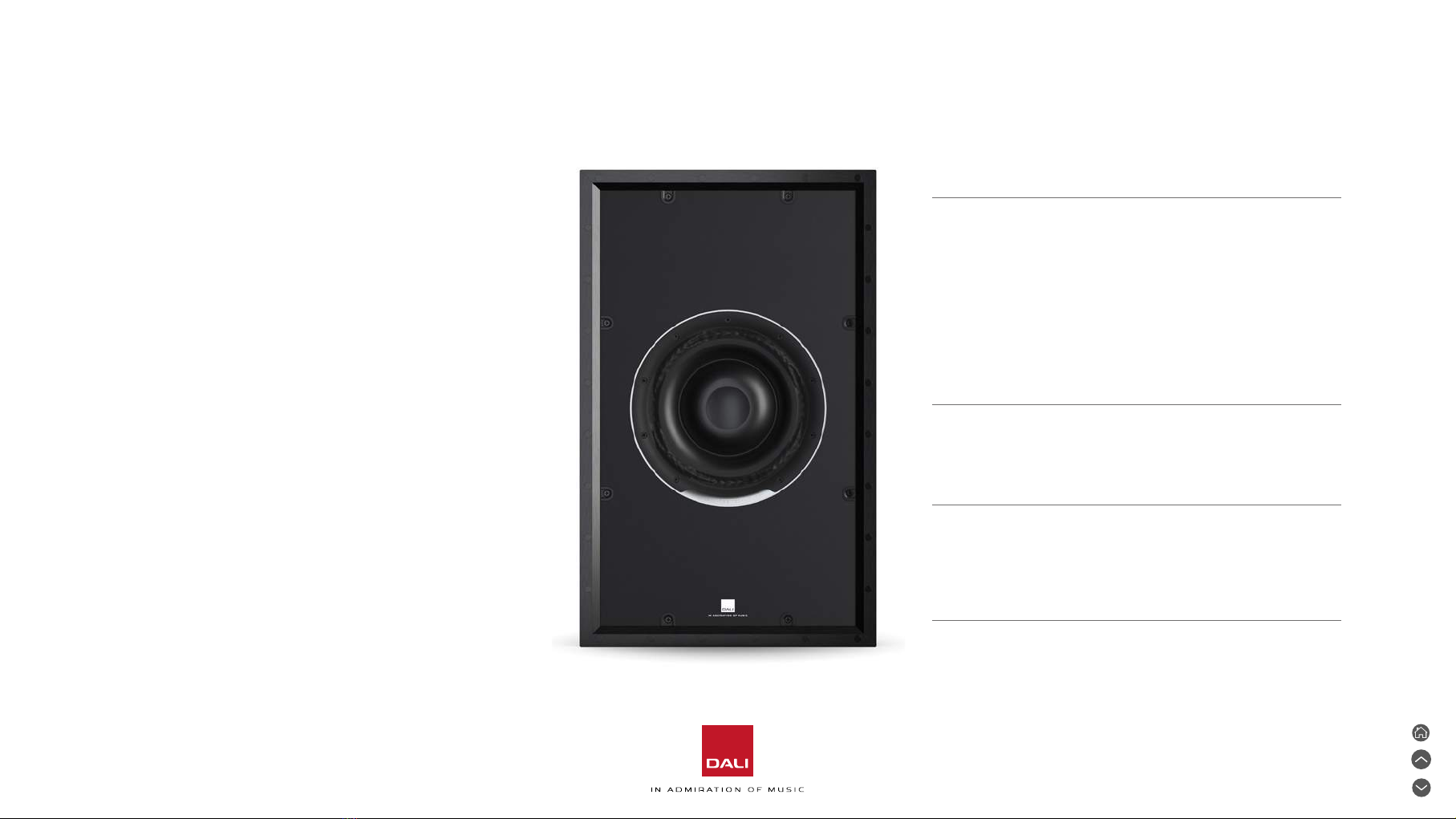
• It is recommended that the PHANTOM IW SUB S-100
should be installed by competent professional audio
installation technicians.
• The SUB S-100 must only be used indoors and never in
extreme humid, hot or cold temperatures.
• The SUB S-100 must only be used with the matching AMP-
2500 DSP amplifier.
• The SUB S-100 should not be exposed to continual direct
sunlight.
• Ensure that there are no service installations such as
electrical or data cables, gas or water pipes, or ventilation
ducts present in the wall at the SUB S-100 mounting
location.
• Ensure that the wall is easily able to support the weight of the
SUB S-100 subwoofer. If necessary consult an appropriately
qualified structural engineer for advice.
• When installing a SUB S-100 in a plasterboard/dry wall we
recommend that two layers of plasterboard are used in the area
around the subwoofer. If it is not possible to use two layers of
plasterboard, we recommend one of these measures:
• Reinforce the single layer plasterboard beneath the dogleg
clamps using wood pieces measuring at least 75 mm x 30 mm x
3 mm thick (3 in x 1.2 in x 0.125 in). Or…
• Install the SUB S-100 on-wall using a DALI PHANTOM S-80
On-Wall Frame (OW FRAME S-80).
• If the SUB S-100 subwoofer is to be installed in a wall where
a vapour barrier is present, ensure that the barrier is not
compromised during installation.
• Ensure that the AMP-2500 DSP driving amplifier is switched o
when connecting cables between the SUB S-100 subwoofer and
the amplifier.
4

3.0 Unpacking
Take care not to damage the box contents
when unpacking the SUB S-100 subwoofer.
Once unpacking is complete, check that all
components listed and illustrated in Diagram 1
are present.
1 x DALI PHANTOM
IW SUB S-100
1 x Grille (magnetic) 1 x Cut-out template 4 x Rubber pads
DIAGRAM 1: CONTENTS
We recommend that packaging materials are
retained in case the SUB S-100 subwoofer requires
relocation. If however the packaging materials are
to be discarded, please ensure they are disposed of
responsibly and recycled where possible.
5

4.0 Positioning and Installation
The SUB S-100 is a passive In-wall subwoofer designed for use in both
conventional stereo and multi-channel home theatre audio systems.
SUBS-100 subwoofers can be installed singularly or in multiples.
Although the SUB S-100 is primarily intended for In-wall installation, it
can also be installed on-wall using an appropriate DALI On-wall Frame, or
be used unmounted lying on its back, also using an On-wall Frame as an
external cabinet.
ON-WALL
INSTALLATION
IN-WALL
INSTALLATION
UNMOUNTED
INSTALLATION
6

DIAGRAM 2: IN-WALL/ON-WALL SUBWOOFER POSITIONING
Example single In-wall or on-wall subwoofer positions Example multiple In-wall or on-wall subwoofer positions
4.1 Positioning
By their very nature, the positioning of
subwoofers such as the SUB S-100 is
less critical than the positioning of stereo
speakers, but still there are some guidelines
to follow, described below and illustrated in
the Diagrams 2 and 3, that will help ensure
optimal performance.
• If a single SUB S-100 is to be installed, it is
best located near the floor of the listening
room in or on the wall that also carries
the front le and right channel speakers.
The closer the subwoofer is to the corner
of the room, the more it will gain acoustic
reinforcement from the room and the less
volume level it will require.
• If a pair of SUB S-100 subwoofers are to
be installed, they are best located near the
floor of the listening room in or on the wall
that also carries the front le and right
channel speakers. As with single subwoofer
installations, the closer the subwoofers
are to the corner of the room, the more
they will gain acoustic reinforcement from
the room and the less volume level they will
require.
7

>50 mm / 1,98 in
DIAGRAM 3: UNMOUNTED SUBWOOFER POSITIONING
Examples concealed installation on the floor beneath furniture
• If SUB S-100 subwoofers are to be installed on the surface of a
wall using an On-wall Frame, or unmounted lying on their back using
On-wall Frames as cabinets, the same location guidelines as for In-
wall installation should generally be followed. The use of SUB S-100
subwoofers unmounted lying on their back however does potentially
enable concealed installation on the floor beneath furniture.
• In either single or multiple subwoofer installations, if it is not practical
to install SUB S-100 subwoofers in the same wall as the front le and
right channel speakers, installation in the side walls of the room, close
to the front corners is also viable.
8

4.2 In-wall Installation
4.2.1 Cables
The choice of cables used to connect SUB S-100 subwoofers to the
AMP-2500 DSP power amplifier is important. Replacing cables following
installation is potentially dicult so it is best to select quali cables from
the start. Your authorised DALI retailer will be able to advise on cable
choice.
When connecting cables to the subwoofer and the amplifier it is
important that correct polari is retained. The red (positive +)
subwoofer terminal must be connected to the positive (+) amplifier
terminal. The black (negative -) subwoofer terminal must be connected
to the negative (-) amplifier terminal.
To insert the cable end into the spring loaded terminals of the IW SUB
S-100 subwoofer, remove the cable insulation so that approximately
12 mm (½ in) of bare wire is exposed. Press the top of the terminal
down and insert the bare wire into the opening. When the wire is fully in
place with no loose strands exposed, release the terminal. Use of the
subwoofer terminals is illustrated in Diagram 4.
DIAGRAM 4:
SUBWOOFER CONNECTION TERMINALS
9

The SUB S-100 subwoofer can be mounted in stud (dry wall) and
plasterboard constructed walls with a minimum free depth of 102
mm (4.02 in). The minimum and maximum plasterboard thickness that
can be accommodated by the SUB S-100 subwoofer fixings is 10 mm
(0.4in) and 50 mm (2.0 in) respectively. The SUB S-100 subwoofer
also requires 19mm (0.74 in) free space to the side, top and boom
in order to enable its dogleg clamps to be deployed. Diagram 5
illustrates SUB S-100 installation dimensions.
If SUB S-100 is to be installed in a particularly thick wall, it may be
necessary to dismount its dogleg clamps from their screws then and
replace them. Dogleg clamps make it possible to install SUB S-100 in
a wall up to 70 mm (2.75 in) thick.
The supplied cut-out template can be used initially to visualise
where a SUB S-100 is to be installed. As part of this exercise, use
a wall stud and pipe/cable finding tool to ensure that the wall space
in which a subwoofer is to be installed is free of obstructions. It is
also important to ensure that the 102 mm (4.02 in) minimum depth
clearance required for SUB S-100 subwoofers is available. If the free
depth available at the installation position is unknown, a test hole can
be drilled and a depth measuring gauge inserted.
DIAGRAM 5:
SUBWOOFER INSTALLATION DIMENSIONS
615 mm
24.2 in
Min.
19 mm
0.75 in
Min.
102 mm
4.02 in
370 mm
14.6 in
Minimum depth
102 mm
4.02 in
Max. 50 mm / 2 in
Min. 10 mm / 0.4 in
Reversed doglegs
Max. 70 mm / 2.8 in
Min. 30 mm / 1,2 in
4.2.2 Wall Aperture
10

NOTES
When installing a SUB S-100 in a plasterboard/dry wall
we recommend that two layers of plasterboard are used
in the area around the subwoofer. If it is not possible to
use two layers of plasterboard, we recommend one of
these measures:
• Reinforce the single layer plasterboard beneath the
dogleg clamps using wood pieces measuring at least 75
mm x 30 mm x 3 mm thick (3 in x 1.2 in x 0.125 in). Or…
• Install the SUB S-100 on-wall using a PHANTOM OW
frame S-80.
If an IW SUB S-100 subwoofer is to be uninstalled,
loosen the clamp screws by approximately 5 to 20 turns
counter-clockwise to loosen the dogleg clamps. Do not
unscrew more than 20 to 25 turns or the clamp arms
may disengage from their screws.
The SUB S-100 subwoofer incorporates eight dogleg clamps for In-
wall installation. The clamps secure the subwoofer firmly to the rear of
the wall surface on which it is mounted. The dogleg clamps extend out
at a 90degree angle when the screws are initially tightened, and then
compress inwards to provide secure aachment to the wall.
The following tools and items are required to complete a SUB S-100 in-
wall installation:
Saw or knife
Hand cross-head screwdriver (or torque limiting power drill with cross
head bit)
Masking Tape
Cut-out template
Once the position and suitabili of the subwoofer installation location has
been established, the cut-out template can be used to mark where the
wall aperture should be created. It is good practice to tape the cut-out
template at the installation position to ease creation of an accurate cut
line. Proceed then as follows:
4.2.3 In-wall Installation
11

DIAGRAM 6:
IN-WALL SUBWOOFER APERTURE CREATION
615 mm
24.2 in
370 mm
14.6 in
12
1With the cut-out template taped to the wall, use a pencil to mark a cut line.
2Remove the template and drill holes at the four corners of the cut line
suitable for the insertion of a saw or knife. Saw or cut carefully along the
cut line to create an aperture in the wall. Diagram 6 illustrates using the
cut-out template and cuing the aperture.
With the aperture for the SUB S-100 subwoofer created, speaker cable that
has been previously routed within the wall can be found and secured to the
inside wall surface to prevent any undue cable tension when it is connected to
the subwoofer terminals.
If a subwoofer cable has not been previously installed, the open aperture
provides the opportuni for this to be done. The subwoofer cable should be
secured to the inside wall surface to prevent any undue cable tension when it
is connected to the SUB S-100 subwoofer terminals. Leave enough free cable
however to connect to the subwoofer terminals when it is outside the wall.
NOTE
If the cable is unsupported and not secured to the inside wall, it
is possible for a cable gradually to work loose in the subwoofer
terminals under its own weight, potentially resulting in subwoofer
disconnection.
12

3With subwoofer cable accessible, bring the SUB S-100 to
the vicini of the aperture and connect the cable to the
subwoofer terminals as illustrated in Diagram 7.
Depending on cable routing in the wall, the SUB S-100
subwoofer can be installed with the connection terminals
either at the top or the boom.
4Li the SUB S-100 subwoofer into the aperture, being careful
not to trap the cable, and hold it in place. Use a cross-head
screwdriver or drill bit to tighten the eight dogleg clamp
screws located in the subwoofer front panel. It is good
practice to tighten opposite screws in turn.
DIAGRAM 7:
IN-WALL SUBWOOFER CONNECTIONS
NOTE
If the amplifier and audio system are connected and working,
it is good practice at this stage to check the integri and
audio routing of the system by playing some audio and
checking that the subwoofer is operating correctly before it
is installed and secured in the wall.
Place subwoofer in wall.
3Connect cables from the
amplifier to the subwoofer.
4
13

x 8
5Tightening the dogleg clamp screws initially swings
the dogleg clamps outwards, and then pulls them
against the inside surface of the plasterboard,
also compressing the subwoofer gasket. The
screws should not be over-tightened. As soon as
the screws show resistance to turning and the
subwoofer feels secure, they are tight enough. If a
power drill is used it should be a torque limiting pe
and have its torque set to minimum. Installing the
subwoofer in the wall aperture and tightening the
clamps is shown in Diagram 8.
6With the SUB S-100 subwoofer secured in the
wall the magnetically aached grille can be placed
in position. With the grille in place, SUB S-100
subwoofer installation is complete.
DIAGRAM 8:
IN-WALL SUBWOOFER INSTALLATION
NOTE
Be careful not to touch the
driver diaphragm when liing
the subwoofer into the wall.
Use a cross-head screwdriver or drill bit to
tighten the eight dogleg clamp screws.
Place the grille.
65
14

If for structural reasons a SUB S-100 subwoofer cannot be installed
within a wall, the accessory PHANTOM OW frame S-80 can be
employed to provide an installation solution. The On-wall Frame can
be secured to a flat wall and then the SUB S-100 subwoofer installed
within it. Diagram 9 illustrates subwoofer installation in an PHANTOM
OW frame S-80.
Once the PHANTOM OW frame S-80 is secured to the wall, the SUB
S-100 installation procedure is eectively the same as that described
for In-wall installation in Section 4.2.3 of this manual.
4.2.4 On-wall Installation
15

x 8
Mount the DALI PHANTOM OW frame S-80
on the wall in landscape or portrait position.
Ensure the On-wall Frame is level.
Aach the frame to the wall
using fiings and screws
appropriate for the pe of wall.
1
Landscape
Portrait
Pass the cable from the amplifier unit
through the channels of the frame.
Cable diameter: Max 10 mm
2
DIAGRAM 9: ON-WALL INSTALLATION
8 x
Connect cables from the
amplifier to the subwoofer.
3
Use a cross-head
screwdriver or drill
bit to tighten the eight
dogleg clamp screws.
Fit the magnetic grille.
5
4
6
16

In addition to its use to enable on-wall installation, the PHANTOM
OW frame S-80 can also be used to provide an external cabinet for
the subwoofer and enable its unmounted installation. The SUB S-100
and PHANTOM OW frame S-80 assembly should be laid on its back
when used unmounted. Four adhesive felt pads are supplied with the
SUB S-100 and should be applied to the back of the On-wall Frame
to provide cushioning on hard floors. When installed unmounted, the
SUB S-100 and PHANTOM OW frame S-80 assembly can potentially
be concealed beneath furniture. Diagram 10 illustrates use of a SUB
S-100 and PHANTOM OW frame S-80 assembly.
4.2.5 Unmounted Installation
17

x 8
DIAGRAM 10: UNMOUNTED INSTALLATION (FOR PLACEMENT ON FLOOR)
1Pass the cable from the amplifier unit
through the channels of the frame.
Place the 4 rubber feet on the rear
side of the DALI PHANTOM OW
frame S-80.
2Connect cables from the
amplifier to the subwoofer.
3
Use a cross-head screwdriver or drill bit to
tighten the eight dogleg clamp screws.
4Place the grille.
5
18

5.0 Cleaning 6.0 Disposal
If your IW SUB S-100 requires cleaning,
use only a dry cloth to dust its surfaces.
Do not use any cleaning fluids.
This product contains electrical or electronic materials. The
presence of these materials may, if not disposed of properly, have
potential adverse eects on the environment and human health.
Presence of this label on the product means it should not be
disposed of as unsorted waste and must be collected separately.
As a consumer, you are responsible for ensuring that this product
is disposed of properly.
19

7.0 Technical Specifications
DALI PHANTOM S SUB S-100*
Frequency range 26 - 250 Hz, ±3 dB
Sensitivi 84 dB @ 1 m for 2.83 V
Nominal impedance 6 ohm
Recommended amplifier power 200 - 500 W RMS
Recommended amplifier DALI PHANTOM AMP-2500 DSP
Maximum SPL 110 dB @ 1 m
Low frequency driver 1 x 10 inch long throw, low profile
Low frequency diaphragm Anodised aluminium
Connection input Single wire
Enclosure pe Closed box / Infinite bae
Installation location In-wall / On-wall / Floor
Outer dimensions incl. grille (H x W x D) 657 x 412 x 107 mm / 25.87 x 16.22 x 4.22 inches
Outer dimensions excl. grille (H x W x D) 647 x 402 x 106 mm / 25.5 x 15.9 x 4.21 inches
Cut-out dimensions (H x W) 615 x 370 mm / 24.2 x 14.5 inches
Mounting depth 102 mm / 4.02 inches
Wall thickness (total dog-leg span) 10 - 70 mm / 0.4 - 2.8 inches
Weight incl. grille 17,25 kg / 38.03 lb
Shipping weight 21 kg / 46.3 lb
Finish Black
Accessories Cut-out template
Front grille
Rubber pads
Optional Accessories PHANTOM PHANTOM OW frame S-80
DALI CONNECT SC F222C (speaker cable)
DALI CONNECT SC F215C (speaker cable)
* All SUB S-100 specifications are measured driven by the PHANTOM CI AMP-2500 DSP amplifier
20
Other manuals for PHANTOM IW SUB S-100
2
Table of contents
Other Dali Speakers manuals

Dali
Dali Euphonia Series User manual

Dali
Dali EPICON User manual

Dali
Dali PHANTOM H-50 User manual

Dali
Dali Opticon User manual

Dali
Dali MOTIF LCR User manual

Dali
Dali PHANTOM S Series User manual

Dali
Dali elegance User manual

Dali
Dali KORE User manual

Dali
Dali SUITE User manual

Dali
Dali OPTICON 1 MK2 User manual