Dalton MOBILITY 800 User manual

OPERATING AND PARTS MANUAL
WIDE SPREAD SPREADERS
2021
DaltonAg.com 800.342.7498
602 E. Van Buren Lenox, Iowa 50851

TABLE OF CONTENTS
TO YOU THE OWNER.............................................................................................................................. 1
LIMITED WARRANTY STATEMENT........................................................................................................... 2
NEW MACHINE CHECKOUT..................................................................................................................... 3
OPERATION AND SAFETY......................................................................................................................... 4
LUBRICATION SCHEDULE......................................................................................................................... 5
LUBRICATION DETAIL ............................................................................................................................. 6
BOLT TORQUE CHART.............................................................................................................................. 7
MACHINE ADJUSTMENT.......................................................................................................................... 8
SPECIFICATIONS....................................................................................................................................... 9
SPREAD ADJUSTMENT AND APPLICATION RATES.................................................................................... 10
SPREAD PATTERN DETAILS....................................................................................................................... 11
60’ SPREAD SETUP................................................................................................................................... 12
90’ SPREAD SETUP.................................................................................................................................... 13
DISTRIBUTOR BLADE TUNING.................................................................................................................. 14
60’ SPREAD PATTERN DECAL.................................................................................................................... 15
90’ SPREAD PATTERN DECAL.................................................................................................................... 16
60’ OR 90’ SPREAD PATTERN DECAL, VARIABLE RATE.............................................................................. 17
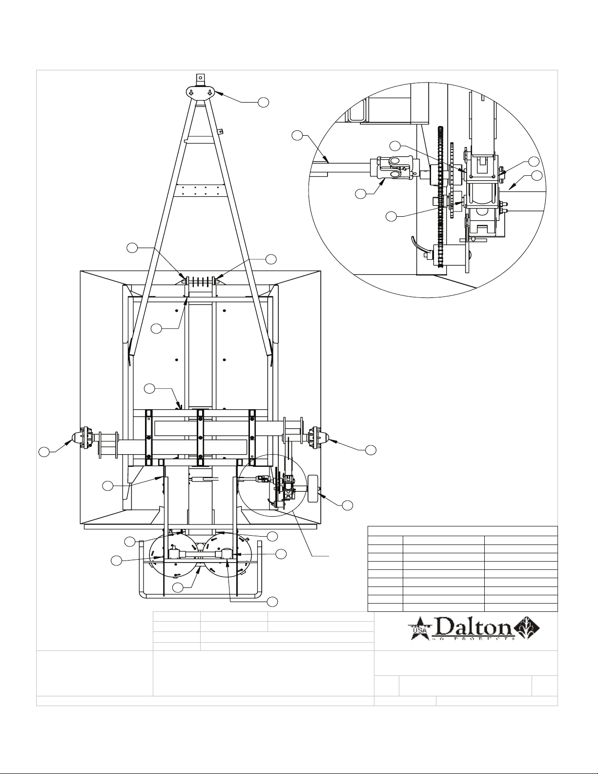
FRAME AND DRIVELINE............................................................................................................................ 18
540 PTO.................................................................................................................................................... 19
1000 PTO.................................................................................................................................................. 20
8 TON AXLE/HUB PARTS........................................................................................................................... 21
10 TON AXLE/HUB PARTS......................................................................................................................... 22
GROUND DRIVE ASSEMBLY....................................................................................................................... 23
FRONT TANK ASSEMBLY............................................................................................................................ 24
GATE JACK ASSEMBLY............................................................................................................................... 25
REAR AREA ASSEMBLY.............................................................................................................................. 26
IDLER MOUNT, CHAIN BELT...................................................................................................................... 28
DISTRIBUTOR GEAR BOX.......................................................................................................................... 29
HYDRAULIC SPINNER GEAR BOX.............................................................................................................. 30
TRACTOR HYDRAULIC DRIVEN SPINNERS................................................................................................ 31
HYDRAULIC SPINNER DRIVE LAYOUT....................................................................................................... 32
DIGITAL READOUT.................................................................................................................................... 33
VARIABLE RATE CONTROL, ELECTRICAL PLAN.......................................................................................... 34
VARIABLE RATE CONTROL, HYDRAULIC PLAN.......................................................................................... 35
SPREADER CONSTANT VALUE................................................................................................................... 36
CALIBRATION NUMBERS FOR VARIABLE RATE SPREADERS 360 ENCODER............................................... 37
SCALE DETAIL............................................................................................................................................ 38
GATE MARKER DECAL............................................................................................................................... 39
DECAL LAYOUT.......................................................................................................................................... 40
PARTS ORDERING PROCEDURE................................................................................................................ 42

1
TO YOU, THE OWNER
Your Dalton Ag Equipment is the most modern, up-to-date, versale, machine available for ferlizer
applicaon. The machine is the result of many years of experience, research, development and tesng of
equipment for ferlizer applicaon. It is soundly engineered and carefully built to rigid specificaons. It is of
rugged and simple construcon, with a minimum of moving parts.
However, to obtain maximum performance from your Dalton Ag Equipment, it is necessary to follow the
instrucons and safety suggesons in this manual. Each secon has been carefully prepared for the purpose
of providing needed and valuable informaon to the owner and operator. Each operator of this unit should be
familiar with the contents of this manual. Keep it in a safe and convenient locaon. THERE ARE MANY SAFETY
SUGGESTIONS (CAUTION AREAS) PRINTED THROUGHOUT THIS MANUAL. CAREFULLY READ THEM ALL BEFORE
OPERATING THIS UNIT.
DESIGN IMPROVEMENTS
Dalton Ag Products follows a policy of connuous products improvement. We therefore reserve the right to
make design improvements, and changes in specificaons and prices, without incurring obligaons to make
revisions or addions to equipment previously sold.
REGISTER
WARRANTY
ONE OF
FOUR WAYS
• Register on-line at:
www.daltonag.com
• Fax your completed warranty registraon form to:
641-569-7033
• Email your completed warranty registraon form to:
• Mail your completed warranty registraon form to:
Dalton Ag, Inc.
P.O. Box 70
Lenox, IA 50851

2
DaltonAg.com 602 E. Van Buren Lenox, Iowa 50851 PHONE: 800.342.7498
FAX: 641.569.7033
DALTON AG PRODUCTS warrants to the original purchaser only that all products manufactured under the Dalton Ag and Mobility
Brands will be free from defects in material and workmanship under normal use and service.
DALTON AG’s obligation under this warranty is limited to repairing or replacing, as it may elect, free of charge and without charge
for installation, at the place of business of a dealer or distributor authorized to handle the equipment covered by this warranty or at
a DALTON AG facility, any parts that prove, in DALTON AG's judgment, to be defective in material or workmanship within two (2)
years after delivery to the original purchaser. DALTON AG shall not be liable for personal injuries or any special or consequential
damages of any kind, either direct or indirect. This warranty is subject to acts of God, fire and existing conditions of supply and
demand, production, ability or inability to deliver, or for any other valid reason beyond the reasonable control of DALTON AG. No
distributor, dealer, agent or DALTON AG employee (other than DALTON's President in writing) is authorized to extend or make any
other or further express or implied warranty or incur any additional obligation on DALTON AG’s behalf in connection with the sale of
this product.
Customer Responsibility
Product Registration - It is a condition of this warranty that the original purchaser fill out the warranty card furnished by DALTON AG
and return it to DALTON AG to be recorded in DALTON AG’s owner file. Registration may also be done on line at
www.DaltonAg.com/warrantyregistration. If the original purchaser's card or electronic registration is not on file at DALTON AG’s
office, the warranty period will extend only from date equipment was picked up or shipped from the DALTON AG plant.
Maintenance - It is the customer’s responsibility to maintain their equipment in accordance with the instructions provided in the
Operator’s Manual. DALTON AG recommends that you keep records and receipts as the customer may be required to verify the
maintenance instructions have been followed.
Operation – It is the customer’s responsibility to operate the equipment only for the purpose for which it was designed and in
accordance with all safety and operational recommendations contained in the Operator's Manual. If a defect in materials or
workmanship occurs, it is the customer’s responsibility to cease operating the equipment until authorized repairs are made.
Damage incurred from continued operation after a defect is discovered may not be covered by this warranty.
What this Warranty Covers
This warranty covers failures caused by defects in materials or workmanship only.
This Warranty does not cover failures caused by:
-Improper operation
-Natural calamities
-Unauthorized modifications
-Unauthorized repairs
-Use of Non DALTON AG parts
-Neglected maintenance
-Usage contrary to the
intended purpose of the
product
This Warranty does not cover replacement of Wear or Maintenance Items including, but not limited to:
-Lubricants
-Filters
-Hoses
-Tires
-Disks
-Chains
-Idlers
-Blades
-Belts
-Bearings
This Warranty does not cover:
Pickup and delivery of the equipment
Service Calls or Travel Time to and from sites
Rental of replacement equipment during repair period
Products that have been declared a total loss and subsequently salvaged
Overtime labor charges
Parts Warranty
DALTON AG warrants its replacement parts against defects in materials or workmanship for a period of 90 days or the remainder of
the product warranty, whichever is longer under the terms set out above. Remedy for defective replacement parts for units that are
beyond the original product warranty, will be limited to replacement of the failed part.
LIMITED WARRANTY STATEMENT

3
NEW MACHINE CHECKOUT
Before aempng to use or operate the spreader it is important to be thoroughly familiarized with the contents of
this manual. Then the machine should be checked using the following check list:
1. Ground drive re inflated to 22 PSI. Tires inflated to manufacturing specificaons.
2. All bearings lubricated and ghtly mounted with collars securely locked.
(See lubricaon schedule page 5.)
3. Conveyor chains, drive chain & ground drive chain adjusted to correct tension. Conveyor chain should
be flush or just below the boom of the trough in the area approximately 2’ behind the front roller.
4. Sprockets ghtened & in proper alignment.
5. Inspect enre machine for loose bolts, especially in the spinner assembly and drive line area.
6. Distributor fan blades set properly. (See spread adjustment and applicaon rates)
7. Place 1/2” material on top of chain, lower gate to material, set pointer at 1”.
8. Tighten wheel bolts daily – 95 foot pounds single axle spreaders.
9. Check drive line for ease of operaon by turning shaby hand. If the foregoing inspecon reveals
that addional lubricaon or adjustment is required, refer to the proper secon of this manual for
detailed instrucons.
10. Ground drive wheel and universal joint shear pins in place and ght.
11. Check both spinner gear boxes for oil; fill to level of pipe plug with SAE No. 90 non-detergent oil.

4
OPERATION
SPREADER SAFETY
Before starng in moon please read the following words of cauon.
A. It is recommended that inial spreading be done in as low a range as possible to permit easy break-in.
B. Always shut offor disconnect power to spreader before aempng to repair or adjust the spreader.
C. Do not transport machine with ground drive wheel engaged.
D. NEVER back-up spreader with ground drive wheel engaged.
E. Make sure that the towing vehicle brakes are operang properly and are capable of stopping the towing vehicle.
F. If a pick-up is used as the towing vehicle, it is wise to add ballast for addional safety and tracon. We
recommend that all towing vehicles be ballast loaded to their recommended G.V.W.
G. Hitches should be of heavy construcon and should be welded or bolted directly to the towing vehicle frame.
Hitches should be checked rounely for loose bolts, cracked welds, etc.
H. Never tow a spreader with a drawbar pin less than 1” in diameter. Pins should also have a locking device.
I. Do not tow spreader at speeds in excess of 20 mph loaded or 40 mph empty.
J. Remember, that the stopping and braking distances vary with load and vehicle speed. It is well to familiarize
yourself with the characteriscs of your machine under different load and speed condions.
K. Be sure to aach safety break-away chain and the safety chain to towing vehicle to assure control of spreader in
the case of pin or hitch failure.
L. The unit is designed for hitching to vehicles with drawbar heights between 12 and 18 inches above the ground
level. It will operate with all standard tractor hitches and PTO’s. WARNING: Hydraulically mounted drawbars
must be securely and mechanically locked because a fully loaded spreader applies a load in the order of 2000 lbs.
to the hitch.
M. WARNING: Remember this unit is designed for agricultural use only and is primarily an off-the-road vehicle and
should be towed at tractor speeds ONLY, not to exceed 20 mph loaded or 40 mph empty. Inspect hubs rounely
to see if they are heang, which indicates either a need for lubricaon or improper adjustment of brakes or
bearings, also check stud nuts for ghtness.
N. WARNING: The maximum capacity of this unit is 8 tons (800) or 270 cubic feet and 10 tons (1000) or 333 cubic
feet, based on a material density of 60 pounds per cubic foot. DO NOT EXCEED THIS LIMIT!
OPERATING INSTRUCTIONS
Please read the following completely before spreading.
1) Aach spreader to towing vehicle, make sure hitch and hitch pin are sound.
2) Aach PTO shato proper rpm PTO.
3) Spinner discs, adjustable chute and conveyor floor should be clean for accurate metering.
4) Set metering gate to desired spread rate according to decal on the back end sheet of tank. Always keep the
machine in the lowest possible range.
5) Before starng to spread, rotate the ground drive wheel several revoluons by hand to make sure the conveyor
chain is operang freely. If chain is frozen or moves with too much resistance, correct problem before using
spreader.
6) If the ground drive wheel operates properly, check with chain and sprocket arrangement for desired range
seng and chain tension.
7) When spreading is complete, disengage ground drive assembly from the re and install transport lockup.

5
(4) BEARINGS
(2) U-JOINTS
(1) BEARING
(4) U-JOINTS
(2) TELESCOPING TUBES
CONVEYOR DRIVE ALL MODELS (6) BEARINGS
(2) SHAFT HOUSINGS
(2) U-JOINTS
TELESCOPING TUBE
(2) SQUIRTS OF SAE 90 OIL INTO JACK
CRANK
OIL CAP
CHAINS OIL LUBRICATE PIN JOINTS WITH SAE 80-90
PTO SHAFT GREASE (2) U-JOINTS AND SLIP TUBE
SPINNER GEARBOX GREASE
UNIVERSAL GREASE ON EACH FITTING
UNDER SPINNER HUB
DRIVE SHAFT SPLINES
SPINNER GEAR BOX
WHEEL BEARINGS
GEAR BOXES
REPLACE WORN OR FAILED PARTS
TIGHTEN LOOSE BOLTS
TOUCH-UP PAINT
DAILY LUBRICATION SCHEDULE
WEEKLY LUBRICATION SCHEDULE
MONTHLY LUBRICATION SCHEDULE
ANNUAL LUBRICATION SCHEDULE
DRIVELINE
GROUND DRIVE
ALL MODELS
GROUND DRIVE
ADJUST TENSION OF CONVEYOUR AND DRIVE
CHAINS (SEE MACHINE CHECKOUT)
CHECK GROUND DRIVE TIRE INFLATION (22
PSI)
CORRECT BELT TENSION
WEEKLY
SEMI-ANNUALLY
WASH SPREADER
DRAIN, FLUSH, AND REFILL WITH SAE 90 OIL
Pay particular attention to the daily cleaning and greasing of the telescoping tube assembly.
ALL MODELS
COAT WITH GREASE OR ANTI-SEIZE COMPOUND
CHECK TO SEE THAT OIL LEVEL IS UP TO OIL LEVEL PLUG.
USE SAE 90 OIL
REPACK
LUBRICATION SCHEDULE
MAINTENANCE SCHEDULE

6
LUBRICATION DETAIL
$
'(7$,/$
6&$/(
/8%5,&$7,216&+('8/(
6/,3-2,17
'$,/<
3,927%86+,1*
(9(5<+56
81,9(56$/-2,17
(9(5<+56
%$//%($5,1*
(9(5<+56
$&78$725
(9(5<+56
63,11(5+8%
(9(5<+56
*($5%2;
(9(5<+56
*$7(-$&.2,/
:((./<
:+((/%($5,1*
7:,&($<($5
&+(&.('%<
6KHHW
$
5,&+6027+(56
7+(,1)250$7,21&217$,1(',17+,6
'5$:,1*,67+(62/(3523(57<2)
'$/721$*$1<5(352'8&7,21,1
3$5725$6$:+2/(:,7+2877+(
:5,77(13(50,66,212)'$/721$*,6
352+,%,7('
35235,(7$5<$1'&21),'(17,$/
'5$:1%<
&21),*
35,17'$7(
&200(176
':*
6,=(
$
6+((77,7/(
5(9
6&$/(
'HIDXOW
6+((72)
/8%5,&$7,216&+('8/(
)253$576&$//
ZZZ'DOWRQ$JFRP

7
IMPORTANT : Over ghtening hardware can be as damaging as under ghtening.
Tightening beyond recommended torque will reduce the fastener’s shock load capacity.
WARNING: Never work around any raised implement while in the
raised posion without using safety lockups.

8
MACHINE ADJUSTMENT
WHEEL BEARING ADJUSTMENT
Aer repacking or when inspecng wheel bearings, the following adjustment procedure should be followed. Place flat
washer and spindle nut on spindle. Turn hub as you ghten nut. When a pronounced drag is felt in the bearings, back
offnut one complete slot. If necessary connue to back offthe nut unl the next slot aligns with the coer pin hole and
install coer pin and dust cap.
CONVEYOR CHAIN ADJUSTMENT
Loosen chain take-up locking nuts on outside of front end of trough. Adjust take-up bolts evenly unl chain clears main
frame members and axle tube by ¾” ½”. Inspect shabearing mounng bolts and shalocking collars for ghtness of set
screws (6 places). Reset take-up locking nuts.
STORAGE
Before storing the spreader for more than a few days, the machine should be emped completely and thoroughly
washed both inside and out. This precauon will minimize the severity of ferlizer acid corrosion, extend the useful life
of the machine, and prevent damage to drive line and conveyor chain from ferlizer compacon and caking. We further
recommend that the machine be thoroughly greased aer washing.
Before operang the machine aer extended periods of storage, re-lubricate the enre spreader in accordance with the
lubricaon secon of this manual. Also check the enre spreader, following the New Machine Checkout Procedure to be
found in a foregoing secon of the manual.
Remember that oil and grease are your least expensive corrosion inhibitors.
ADDITIONAL INSTRUCTIONS:
CAUTION
Do not operate your spreader with less than one and a half (1 1/2) inch of metering gate opening as material will com-
pact against metering gate and cause failure of the conveyor chain.
CAUTION
Do not disconnect implement from tractor with material remaining in box.

9
FEATURES MOBILITY800 MOBILITY1000
Capacity(Weight) 8Tons 10Tons
HopperLength 120" 148"
HopperWidth 93" 93"
HopperCapacity(Volume) 270cu.ft. 333cu.ft.
OverallLength 230" 250"
OverallHeight 120" 120"
OverallWidth96" 96"
EmptyWeight 4,900lbs. 5,900lbs.
GroudClearance 45"underSpinners
37"underFrame
45"underSpinners
37"underFrame
SpreadPattern 60',90' 60',90'
HopperConstruction 409StainlessSteel 409StainlessSteel
SpinnerDriveSystem 540/1000PTO:Standard
TractorHydraulic:Optional TractorHydraulic
Spinners DualGearboxDrivenDualGearboxDriven
Jack 5,000lbs. 5,000lbs.
Hitch HDClevis:Standard
CAT4BullPull:Optional CAT4BullPull
Axle 80"Ͳ120"adjustable 80"Ͳ120"adjustable
ConveyorDrive 2SPDGroundDriveorHydraulic Hydraulic
SRTRollTarp Standard Standard
Tires&Wheels
380/90/R46
380/90/R46
Duals:Optional
Floaters:850/50R30.5Optional
LightKit Standard Standard
VariableRateReady Optional Standard
ScaleKitwithMonitorOptional Optional
StandardPowderCoatPaintColors White White
Warrant
y
24Months 24Months
WIDESPREADSERIESSPREADERSPECIFICATIONS
SPECIFICATIONS

10
SPREAD ADJUSTMENT AND APPLICATION RATES
For accurate and precise spreading rates, it is necessary that you know the weight in pounds per cubic foot of the
material to be spread. If this is not known, the weight can be quickly and accurately determined by the following
method:
1. Weigh an empty one gallon container.
2. Fill level full with the material to be used.
3. Weigh container and material, and then subtract the weight of the container to obtain the weight of the
material.
4. Mulply the weight of the material by 7.5 to obtain the weight of the material in pounds per cubic foot.
Example: Typical Material-Potash
1) Weight of empty one gallon container 1.00 lbs.
2) Weight of filled container 10.35 lbs.
3) Weight of container (net) 9.35 lbs.
4) 9.35 X 7.5 70.125 lbs. /cu .
You would therefore use the column on the Spread Chart headed 70 to determine the proper gate opening
for the desired applicaon rate.
Your Mobility Spreader with its heavy-duty distributor discs and blades will apply most materials in a 50 foot wide
swath.

11
SPREAD PATTERN DETAILS
An operaonal characterisc of this type of machine is the possibility of overloading the distributors at high
rates of applicaon. Such an overload results in an alteraon of the spread paern to a narrower swath with
heavier applicaon at the center. This can be avoided by reducing speed when using high applicaon rates.
Cauon: Be extra careful to check your spread paern when using high applicaon rates. Adjust your driving
paern to the actual delivered spread swath, the adjustment of the machine, and the material being used. When
applicaon rates are in excess of 700 pounds per acre, the ground speed should be proporonately reduced, We
recommend that for very high applicaon rates, to insure uniformity of applicaon, that two lighter applicaon
passes be made preferably placing your second pass over the lap lines of the first pass. This also is recommended
pracce when spreading under very windy condions or with a material that segregates easily. If your effecve
spread paern is more, the Metering Gate seng should be increased proporonately, according to the percent-
age of your spread width. The gate seng should likewise be decreased if your effecve spread paern is less.
Your spread paern can be checked accurately and visually on a freshly worked, level area of ground. Such an
area is also ideally suited to adjusng and fine tuning your machine. The following diagram graphically illustrates a
typical spread paern.
Note on the illustraon below that the lap point occurs at the point where the applicaon rate is one-half
of the spread chart rate. The profile of the spread paern tapers at both edges and has a wide uniform area in
the center. By careful aenon to the lap point during applicaon, a very uniform and even spread rate can be
aained. The Mobility Spreaders have been designed to provide this good and uniform tapered profile to make
spread width less crical. However, excessive or insufficient overlap of passes will result in a poor applicaon pat-
tern in the lap area of the total spread paern. If you can aain this spread paern and pay careful aenon to
the lap points, the doed line on the illustraon will represent your actual overall spread paern.

12
60’ SPREAD SETUP
SPREAD SET UP, WIDE SPREAD
F O R P A R T S , C A L L 1 . 8 0 0 . 3 4 2 . 7 4 9 8
w w w . D a l t o n A g . c o m
CHECKED BY
SHEET 2 OF 2
3/12/2021
3/16/2021
60' SPREAD
SCALE: 1:6
60' SPREAD A
PROHIBITED.
PROPRIETARY AND CONFIDENTIAL
DRAWN BY
CONFIG.
PRINT DATE
COMMENTS:
DWG:
SIZE
A
SHEET TITLE: REV
THE INFORMATION CONTAINED IN THIS
DRAWING IS THE SOLE PROPERTY OF
DALTON AG. ANY REPRODUCTION IN
PART OR AS A WHOLE WITHOUT THE
WRITTEN PERMISSION OF DALTON AG IS
--
2
ITEM NO. PART NUMBER DESCRIPTION QTY.
1 4431277 SPINNER BLADE, 11 INCH, LH 6
2 4431277 SPINNER BLADE, 11 INCH, RH 6
ROTATION ROTATION
2
1
VIEWED FROM BACK OF SPREADER
2
1
2
1
2
1
2
1
2
1
BLADES LABELLED SET TO 2ND
HOLE FROM LEFT SIDE OF PATTERN,
VIEWED FROM THE CENTER OF THE DISC.
BLADES LABELLED 2
VIEWED FROM THE CENTER OF THE DISC.
HOLE FROM LEFT SIDE OF PATTERN,
SET TO 3RD
1
BLADES LABELLED 2SET TO 2ND
HOLE FROMRIGHT SIDE OF PATTERN,
VIEWED FROMTHE CENTER OF THE DISC.
BLADES LABELLED 1SET TO 3RD
HOLE FROMRIGHT SIDE OF PATTERN,
VIEWED FROMTHE CENTER OF THE DISC.
1

13
90’ SPREAD SETUP
SHEET 1 OF 2
SPREAD SET UP, WIDE SPREAD
F O R P A R T S , C A L L 1 . 8 0 0 . 3 4 2 . 7 4 9 8
w w w . D a l t o n A g . c o m
3/12/2021
3/16/2021
90' SPREAD
SCALE: 1:6
REV
CHECKED BY
90' SPREAD
A
PROHIBITED.
PROPRIETARY AND CONFIDENTIAL
DRAWN BY
CONFIG.
PRINT DATE
COMMENTS:
DWG:
SIZE
A
SHEET TITLE:
THE INFORMATION CONTAINED IN THIS
DRAWING IS THE SOLE PROPERTY OF
DALTON AG. ANY REPRODUCTION IN
PART OR AS A WHOLE WITHOUT THE
WRITTEN PERMISSION OF DALTON AG IS
--
1
ALL BLADES SET TO 3RD HOLE FROM
2
1
VIEWED FROM BACK OF SPREADER
2
1
2
1
2
1
2
1
LEFT SIDE OF PATTERN, VIEWED FROM
THE CENTER OF THE DISC
2
ALL BLADES SET TO 3RD HOLE FROM
RIGHT SIDE OF PATTERN, VIEWED FROM
THE CENTER OF THE DISC
ROTATION ROTATION
ITEM NO. PART NUMBER DESCRIPTION QTY.
1 4431277 SPINNER BLADE, 11 INCH, LH 6
2 4431277 SPINNER BLADE, 11 INCH, RH 6
12

14
DISTRIBUTOR BLADE TUNING
FINE TUNING OF DISTRIBUTOR AND BLADE SETTINGS
All Mobility Spreaders are given an average standard factory seng of distributor blades. Such a seng, of course,
cannot be perfect for all field condions and materials. The following informaon will be helpful in adjusng the
distributor blades on your machine to give opmum performance for your specific condions.
Your spread paern will be affected by 1) the material used, 2) the distributor blade seng, and 3) the rotaon speed
of the distributors. The distributors are designed to be operated at 750 RPM (540 tractor P.T.O. RPM). A plus or minus
10% change in distributor RPM will increase or decrease spread paern width accordingly. An increase in PTO RPM will
tend to deposit less material at the center of the spread paern, while a decrease will deposit more material at the
center. The physical characteriscs of the materials being spread, which are important to the spread paern, include
bulk density, parcle size, parcle shape, physical strength and rugosity or surface roughness. For best performance it is
recommended that you fine tune your machine to the material being used. The spreading profile and spread swath
width can be changed drascally by alteraon of the seng of the distributor blades. The drawing on the next page
shows had blades may be extended from or retracted toward the center of the disc. Also, the angle of blade
intersecon with a radius of the disc may be altered. They may be advanced toward coincidence with the disc radius or
retarded away from it. Further, blade lengths are not all equal. These adjustments affect the spread paern in the
following ways:
1. Advance long blades--more material to the outside of spread paern; also will increase spread paern
width.
2. Retard long blades--opposite effect of above.
3. Advance short blades—helps eliminate problem of streaking in the middle of spread paern.
4. Retard short blades—puts more material in the center of spread paern.
5. Extend blades away from center of spinner—increases spread width somewhat.
6. Retract blades (more towards center of spinner)—opposite effect of above.
7. Moving flow divider (or chute) toward the front of spreader will tend to put more material in center of
spread paern. This is because material is deposited on outer edge of spinner causing it to leave earlier.
8. Moving divider toward the rear of the spreader has the opposite effect.
9,(:(')520%$&.2)635($'(5
527$7,21
527$7,21
5(7$5'('%/$'(
$'9$1&('%/$'(

15
60’ SPREAD

16
90’ SPREAD

17
60’ to 90’ SPREAD, VARIABLE RATE

18
FRAME AND DRIVELINE
%2/721
%8//38//+,7&+&$7
%8//38//3,1
237,21$/
+,7&+
67$1'$5'
+'&/(9,6
%2/7;
187&(17(5/2&.
$
5,&+6027+(56
352+,%,7('
35235,(7$5<$1'&21),'(17,$/
':*
$1'72152:&523
&+(&.('%<
)253$576&$//
)5$0('5,9(/,1(52:&5236
5(9
35,17'$7(
'5$:1%<
6&$/(
&21),*
6+((77,7/(6,=(
&200(176
)5$0('5,9(/,1(52:&523
$
6+((72)
7+(,1)250$7,21&217$,1(',17+,6
'5$:,1*,67+(62/(3523(57<2)
'$/721$*$1<5(352'8&7,21,1
3$5725$6$:+2/(:,7+2877+(
:5,77(13(50,66,212)'$/721$*,6
w w w . D a l t o n A g . c o m
5(9,6,216
5(9 '(6&5,37,21 '$7( $33529('
3$57180%(5 4
721721)5$0(
%2/71&[3/7'
%2/71&[*3/7'
3,//2:%/2&.%($5,1*
6+$)7
%($5,1*$50)5217
63/,732/<%($5,1*+286,1*
63/,732/<,16(5721/<
6+,(/'02817,1*%5$&.(75+
6+,(/'02817,1*%5$&.(7/+
)/$7:$6+(566
)/$7:$6+(566
1871&66
6+$)7)5217[721
38//(<',$)25372
3$57180%(5 4
38//(<',$)25372
38//(<',$)25372
38//(<',$)25372
372&203/(7(1
530372+$/)6+$)7
%(/7
8-2,17'5,9(6+$)7
6+$)7%$&.[721
3726+,(/'
7$///%6-$&.
&$55,$*(%2/7[
635,1*
/2&.187
+'+,7&+&/(9,6
% %8//38//+,7&+&$7
/2&.:$6+(567'66
This manual suits for next models
1
Table of contents
Other Dalton Spreader manuals