Dalton Mobility 100 User manual

OPERATING AND PARTS MANUAL
MOBILITY 100 &150
www.DaltonAg.com
602 E. Van Buren Lenox, IA 50851 800.342.7498

TABLE OF CONTENTS
TO YOU, THE OWNER..........................................................................................1
SPECIFICATIONS..................................................................................................2
NEW MACHINE CHECKOUT............................................................................. 3
OPERATION............................................................................................................4
MAINTENANCE.....................................................................................................5
LUBRICATION DETAIL....................................................................................... 6
MACHINE ADJUSTMENT....................................................................................7 - 8
SPREAD ADJUSTMENT AND APPLICATION RATES................................... 9
SPREAD PATTERN DETAILS..............................................................................10
STANDARD SPREAD SETUP............................................................................... 11
DISTRIBUTOR BLADE TUNING........................................................................12
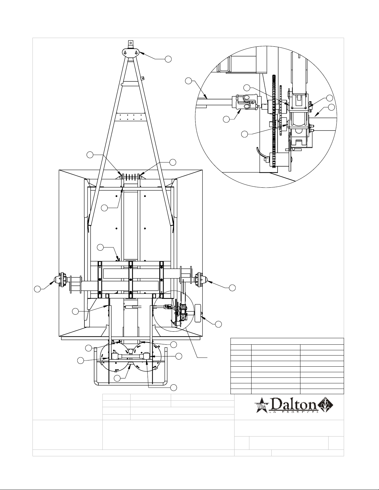
FRAME AND DRIVELINE 100 & 150..................................................................15
540 PTO.....................................................................................................................16
1000 PTO.................................................................................................................. 17
6 BOLT, HEAVY HUB ASSEMBLY.......................................................................18
GROUND DRIVE ASSEMBLY..............................................................................19 - 20
FRONT TANK ASSEMBLY................................................................................... 21
REAR AREA ASSEMBLY...................................................................................... 22 - 23
DISTRIBUTOR GEAR BOX #1003737................................................................ 24
HYDRAULIC SPINNER GEAR BOX.................................................................. 25 - 27
CONVEYOR CLUTCH OPTION......................................................................... 28 - 29
VARIABLE RATE CONTROL, ELECTRICAL PLAN......................................30
VARIABLE RATE, HYDRAULIC........................................................................ 31
BANDER OPTION..................................................................................................32
BOLT TORQUE CHART........................................................................................33
PARTS ORDERING PROCEDURE......................................................................34
LIMITED WARRANTY..........................................................................................35

1
TO YOU, THE OWNER
Your Mobility Spreader is the most modern, up-to-date, versatile, machine available for broadcast application
of bulk fertilizer and other granular materials. The machine is the result of many years of experience, research,
development and testing of equipment for broadcast application. It is soundly engineered and carefully built to
rigid specications. It is of rugged and simple construction, with a minimum of moving parts.
However, to obtain maximum performance from your spreader, it is necessary to follow the instructions and
safety suggestions in this manual. Each section has been carefully prepared for the purpose of providing needed
and valuable information to the owner and operator. Each operator of this unit should be familiar with the con-
tents of this manual. Keep it in a safe and convenient location. THERE ARE MANY SAFETY SUGGESTIONS
(CAUTION AREAS) PRINTED THROUGHOUT THIS MANUAL. CAREFULLY READ THEM ALL BE-
FORE OPERATING THIS UNIT.
DESIGN IMPROVEMENTS
Dalton Ag Products follows a policy of continuous products improvement. We therefore reserve the right to
make design improvements, and changes in specications and prices, without incurring obligations to make
revisions or additions to equipment previously sold.

2
SPECIFICATIONS
100 150
Capacity - Struck (CU FT.) 35
Capacity - Struck (Tons) 1 1.5
Tare Weight 1,320 LBS
Tank Dimensions 72” X 45 1/2”
Overall Length and Width 137” and 68”
Overall Height and Loading Height 66”
Spinner Drive Protection V-Belt V-Belt
Wheel Track 55 1/2”, Non-Adjustable 55 1/2”, Non-Adjustable
Hub (6-Bolt)
& Spindle Rating
PTO Drive 540 RPM 540 RPM
PTO Sha
Tank Material
Tongue Jack 5000# 5000#
Distributor Discs
Conveyor Trough Stainless Steel Stainless Steel
Drive Chains #40 Ground Drive & #40 Ground Drive
#50 Conveyor Drive #50 Conveyor Drive
Metering Gate, Rear Skid
& Take-up Bolts Stainless Steel Stainless Steel
Spreading Width
Spreading Width, Average Material
Spreading Capability
Spindle Diameter
Axle Rating
Conveyor Drive 2-Speed 2-Speed
Gate Jack
2

NEW MACHINE CHECKOUT
Before attempting to use or operate the spreader it is important to be thoroughly familiarized with the
contents of this manual. Then the machine should be checked using the following check list:
1. Ground drive tire inated to 22 PSI. Tires inated to manufacturing specications.
2. All bearings lubricated and tightly mounted with collars securely locked. (See lubrication schedule
page 5.)
3. Conveyor chains, drive chain & ground drive chain adjusted to correct tension. Conveyor chain
should clear frame members by ½ - ¾.
4. Sprockets tightened & in proper alignment.
5. Inspect entire machine for loose bolts, especially in the spinner assembly and drive line area.
6. Distributor fan blades set properly. (See spread adjustment and application rates pages 7 through 25.)
7. Setting of metering gate. With the pointer on the number 1 of the spread rate chart decal, the lower
edge of the metering gate should be 1 ¼” above the trough oor.
8. Tighten wheel bolts daily – 95 foot pounds single axle spreaders.
9. Check drive line for ease of operation by turning shaft by hand. If the foregoing inspection reveals
that additional lubrication or adjustment is required, refer to the proper section of this manual for
detailed instructions.
10. Ground drive wheel and universal joint shear pins in place and tight.
11. Check both spinner gear boxes for oil; ll to level of pipe plug with SAE No. 90 non-detergen
3

OPERATION
SPREADER SAFETY
Before starting in motion please read the following words of caution.
A. It is recommended that initial spreading be done in as low a range as possible to permit easy break-in.
B. Always shut off or disconnect power to spreader before attempting to repair or adjust the spreader.
C. Do not transport machine with ground drive wheel engaged.
D. NEVER back-up spreader with ground drive wheel engaged.
E. Make sure that the towing vehicle brakes are operating properly and are capable of stopping the towing
vehicle.
F. If a pick-up is used as the towing vehicle, it is wise to add ballast for additional safety and traction. We
recommend that all towing vehicles be ballast loaded to their recommended G.V.W.
G. Hitches should be of heavy construction and should be welded or bolted directly to the towing vehicle
frame. Hitches should be checked routinely for loose bolts, cracked welds, etc.
H. Never tow a spreader with a drawbar pin less than 1” in diameter. Pins should also have a locking de-
vice.
I. Do not tow spreader at speeds in excess of 20 mph loaded or 40 mph empty.
J. Remember, that the stopping and braking distances vary with load and vehicle speed. It is well to famil-
iarize yourself with the characteristics of your machine under different load and speed conditions.
K. Be sure to attach safety break-away chain and the safety chain to towing vehicle to assure control of
spreader in the case of pin or hitch failure.
L. The unit is designed for hitching to vehicles with drawbar heights between 12 and 18 inches above the
ground level. It will operate with all standard tractor hitches and PTO’s. WARNING: Hydraulically
mounted drawbars must be securely and mechanically locked because a fully loaded spreader applies a
load in the order of 2000 lbs. to the hitch.
M. WARNING: Remember this unit is designed for agricultural use only and is primarily an off-the-road
vehicle and should be towed at tractor speeds ONLY, not to exceed 20 mph loaded or 40 mph empty. In-
spect hubs routinely to see if they are heating, which indicates either a need for lubrication or improper
adjustment of brakes or bearings, also check stud nuts for tightness.
N. WARNING: The maximum capacity of this unit is 6 tons (600) or 200 cubic feet, based on a material
density of 60 pounds per cubic foot. DO NOT EXCEED THIS LIMIT!
OPERATING INSTRUCTIONS
Please read the following completely before spreading.
1) Attach spreader to towing vehicle, make sure hitch and hitch pin are sound.
2) Attach PTO shaft to proper rpm PTO.
3) Spinner discs, adjustable chute and conveyor oor should be clean for accurate metering.
4) Set metering gate to desired spread rate according to decal on the back end sheet of tank. Always keep
the machine in the lowest possible range.
5) Before starting to spread, rotate the ground drive wheel several revolutions by hand to make sure the
conveyor chain is operating freely. If chain is frozen or moves with too much resistance, correct problem
before using spreader.
6) If the ground drive wheel operates properly, check with chain and sprocket arrangement for desired
range setting and chain tension.
7) When spreading is complete, disengage ground drive assembly from the tire and install transport lockup.
4

MAINTENANCE
LUBRICATION SCHEDULE
Careful observance of the following lubrication schedule is the best preventative maintenance program for
your spreader. We recommend that you establish a rm program to insure lubrication in strict compliance with
the following schedule. Use only good grade pressure gun type grease unless otherwise specied.
Daily Lubrication Schedule
Drive Line All Models 4 bearings, 2 U joints
Ground Drive 1 bearing, 4 U joints, 2 telescoping tubes
Conveyor Drive All Models 6 bearings
Ground Drive All Models 2 sha housings, 2 U joints, telescoping tube, and 2 squirts
of SAE 90 oil into jack crank, oil cap.
Pay particular attention to the daily cleaning and greasing of the telescoping tube assembly.
Weekly Lubrication Schedule
Chains Oil -- Lubricate Pin Joints with SAE 80-90
PTO Sha Grease – 2 U-joints and Slip Tube
Spinner Gearbox Universal grease on each tting under spinner hub
Monthly Lubrication Schedule
Drive Sha Splines Coat with grease or anti-seize compound.
Spinner Gear Box Check to see that oil level is up to oil level plug. Use SAE 90 oil.
Annual Lubrication Schedule
Wheel Bearings Repack
Gear Boxes Drain, Flush and Rell with SAE 90 Oil
MAINTENANCE
Weekly
Wash Spreader
Check Ground Drive Tire Ination (22 psi)
Correct Belt Tension
Adjust Tension of Conveyor and Drive Chains (see machine checkout)
Semi-Annually
Tighten Loose Bolts
Replace Worn or Failed Parts
Touch-Up Paint
5
A
9
9
4
4
4
4
4
4
4
4
6
6
7
5
3
DETAIL A
SCALE 4 : 30
4
4
4
4
3
1
LUBRICATION SCHEDULE
1
SLIP JOINT
DAILY
2
PIVOT BUSHING
EVERY 10 HRS
3
UNIVERSAL JOINT
EVERY 15 HRS
4
BALL BEARING
EVERY 15 HRS
5
ACTUATOR
EVERY 15 HRS
6
SPINNER HUB
EVERY 15 HRS
7
GEAR BOX
EVERY 75 HRS
8
GATE JACK (OIL)
WEEKLY
9
WHEEL BEARING
TWICE A YEAR
CHECKED BY
Sheet1
A
RICH SMOTHERS
THE INFORMATION CONTAINED IN THIS
DRAWING IS THE SOLE PROPERTY OF
DALTON AG. ANY REPRODUCTION IN
PART OR AS A WHOLE WITHOUT THE
WRITTEN PERMISSION OF DALTON AG IS
PROHIBITED.
PROPRIETARY AND CONFIDENTIAL
DRAWN BY
CONFIG.
PRINT DATE
COMMENTS:
DWG:
SIZE
A
SHEET TITLE:
REV
SCALE: 1:26
Default
7/28/2014
2/9/2010
SHEET 1 OF 1
LUBRICATION SCHEDULE
F O R P A R T S , C A L L 1 . 8 0 0 . 3 4 2 . 7 4 9 8
w w w . D a l t o n A g . c o m
LUBRICATION
DETAIL
6

WHEEL BEARING ADJUSTMENT
After repacking or when inspecting wheel bearings, the following adjustment procedure should be followed.
Place at washer and spindle nut on spindle. Turn hub as you tighten nut. When a pronounced drag is felt in the
bearings, back off nut one complete slot. If necessary continue to back off the nut until the next slot aligns with
the cotter pin hole and install cotter pin and dust cap.
CONVEYOR CHAIN ADJUSTMENT
Loosen chain take-up locking nuts on outside of front end of trough. Adjust take-up bolts evenly until chain
clears main frame members and axle tube by ¾” ½”. Inspect shaft bearing mounting bolts and shaft locking col-
lars for tightness of set screws (6 places). Reset take-up locking nuts.
STORAGE
Before storing the spreader for more than a few days, the machine should be emptied completely and thor-
oughly washed both inside and out. This precaution will minimize the severity of fertilizer acid corrosion, ex-
tend the useful life of the machine, and prevent damage to drive line and conveyor chain from fertilizer compac-
tion and caking. We further recommend that the machine be thoroughly greased after washing.
Before operating the machine after extended periods of storage, re-lubricate the entire spreader in accor-
dance with the lubrication section of this manual. Also check the entire spreader, following the New Machine
Checkout Procedure to be found in a foregoing section of the manual.
Remember that oil and grease are your least expensive corrosion inhibitors.
MACHINE ADJUSTMENT
7

Additional Instructions
The ground drive is equipped with the following sprocket combinations:
Low Range Drive Chain on 12 & 72 Tooth Sprockets
High Range Drive Chain on 24 & 48 Tooth Sprockets
CAUTION
Do not operate your spreader with less than one and a half (1 ½) inch of metering gate opening as material will
compact against metering gate and cause failure of the conveyor chain.
CAUTION
Do not disconnect implement from tractor with material remaining in box.
8
This manual suits for next models
1
Table of contents
Other Dalton Spreader manuals

Popular Spreader manuals by other brands


Fisher
Fisher POLY-CASTER 78601 owner's manual

TurfEx
TurfEx RS7200 Owner's/operator's manual

Ferris
Ferris Pathfinder Series Operator's manual

Fayat Group
Fayat Group DYNAPAC S100 operation & maintenance

Art's-Way Manufacturing
Art's-Way Manufacturing X700 Operator's manual & parts list

EASTMAN
EASTMAN CR 500 instruction manual


