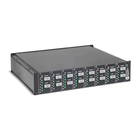
Dan Dugan Sound Design E-3 User manual

Dan Dugan Sound Design
Model E-3 Automatic Mixing Controller
User Guide
Release Date: December 2012
Version: 1.5
Part Number: ME3M
Author: Rob Wenig

Important Safety Instructions and Warnings
The Model E-3’s circuitry is made in the USA and meets applicable national safety standards.
Standards Compliance
The third-party power supply provided with this product has been certified to comply with UL.
Safety Instructions
1. Read these instructions.
2. Keep these instructions.
3. Heed all warnings.
4. Follow all instructions.
5. Do not use this apparatus near water.
6. WARNING! To reduce the risk of fire or electric shock, do not expose this apparatus
to rain or moisture.
7. Clean only with dry cloth.
8. Do not block any ventilation openings. Install in accordance with the manufacturer’s
instructions.
9. Do not install near any heat sources such as radiators, heat registers, stoves, or other
apparatus (including amplifiers) that produce heat.
10. Do not defeat the safety purpose of the polarized or grounding-type plug. A polarized
plug has two blades with one wider than the other. A grounding type plug has two
blades and a third grounding prong. The wide blade or the third prong are provided for
your safety. If the provided plug does not fit into your outlet, consult an electrician for
replacement of the obsolete outlet.
11. Protect the power cord from being walked on or pinched particularly at plugs, conve-
nience receptacles, and the point where they exit from the apparatus.
12. Only use attachments/accessories specified by the manufacturer.
13. Unplug this apparatus during lightning storms or when unused for long periods of time.
14. WARNING! Refer all servicing to qualified service personnel. Servicing is required
when the apparatus has been damaged in any way, such as power-supply cord or plug is
damaged,liquidhasbeenspilledorobjectshavefallenintotheapparatus,theapparatus
has been exposed to rain or moisture, does not operate normally, or has been dropped.
15. WARNING! To reduce the risk of electric shock, DO NOT REMOVE COVER. No
user serviceable parts inside.

Warranty Statement
Warranty: One year parts and labor
Dan Dugan Sound Design warrants that Model E-3 hardware will be free from defects in
components and workmanship for a period of 12 months from the date of invoice. During the
warrantyperiod,Dan Dugan Sound Design will coverthecost of all parts and labortoremedy
the defect, or replace products which prove to be defective. Dan Dugan Sound Design is
not obliged to honor this warranty if the hardware has failed to be maintained and operated
as specified by Dan Dugan Sound Design, in the accompanying documentation, or other
than in accordance with industry standards. Defects caused by unauthorized modifications,
misuse, negligence, act of God or accident are not covered by this warranty. Software is
provided as a convenience, but due to the wide variety of computer systems, cannot be
guaranteed to work. This Limited Warranty is exclusive and no other warranty is expressed
or implied. Dan Dugan Sound Design does not warrant that Dan Dugan Sound Design soft-
ware, or any third-party software, is error free. Third party branded or manufactured
goods are supplied by Dan Dugan Sound Design with care but without responsibility
and subject only to third party suppliers’ warranties. In all other respects Dan Dugan
Sound Design is not liable for consequential damages.


Dugan Model E-3 User Guide
5
Table of Contents
Chapter 1: Introduction ............................................................................................. 9
Model E-3 Modes...................................................................................... 10
Eight-channel........................................................................................ 10
Fourteen-channel ................................................................................. 10
Sixteen-channel.................................................................................... 10
Chapter 2: Quickstart ............................................................................................... 11
Typical Setup.............................................................................................. 11
Linking.......................................................................................................... 13
Chapter 3: Installation and Configuration.................................................. 15
Rack Mounting .......................................................................................... 15
Power Supply ............................................................................................. 16
System Reset............................................................................................. 16
Rear Panel I/O Connections ................................................................ 16
AES .................................................................................................. 17
ADAT .................................................................................................. 18
Music System Threshold Inputs.......................................................... 18
Word Clock.................................................................................................. 18
Linking.......................................................................................................... 19
Patching the Model E-3 as an Insert to your Console ................ 20
Split Outputs............................................................................................... 20
Mix Matrix Outputs................................................................................... 20
Connecting the Model CP-2 Control Panel ..................................... 21
Connecting to a Computer.................................................................... 21

Dugan Model E-3 User Guide
6
Chapter 4: Operation ................................................................................................. 27
How it Works.............................................................................................. 27
Settings ........................................................................................................ 28
If You Must Use a Pre-fader Insert..................................................... 29
Muting Channels .................................................................................. 29
Pre-listening to Muted Channels........................................................ 30
Chapter 5: Dugan Control Panel ....................................................................... 31
The Top Pane ............................................................................................. 32
Add Units Manually.............................................................................. 33
Select Units to Display ........................................................................ 33
Setting Controls ........................................................................................ 34
Naming Units and Channels................................................................. 34
Channel Pane ............................................................................................ 35
Level Indicator...................................................................................... 35
Bypass .................................................................................................. 36
Channel Modes .................................................................................... 36
Preset .................................................................................................. 37
Channel Groups.................................................................................... 38
Override................................................................................................. 38
Meters .................................................................................................. 39
Weight Controls ................................................................................... 39
Master Pane............................................................................................... 42
Selecting the Number of Channels.................................................... 43
Reset .................................................................................................. 43
Meters .................................................................................................. 43
Clock Source ........................................................................................ 44
System .................................................................................................. 44
Mix Bus Matrix...................................................................................... 45
Group Master Controls ........................................................................ 46

Dugan Model E-3 User Guide
7
Dugan Music System and Gain Limiting ......................................... 47
Dugan Music System........................................................................... 47
Gain Limiting........................................................................................ 50
Chapter 6: Updates..................................................................................................... 53
Appendix A: Power-up Commands ...................................................................... 55
System Reset............................................................................................. 55
Network Reset........................................................................................... 55
DHCP On ...................................................................................................... 55
8 or 14/16-Channel Mode.................................................................... 56
Appendix B: Connector Pinouts ........................................................................... 57
Appendix C: Specifications ...................................................................................... 61

Dugan Model E-3 User Guide
8

Dugan Model E-3 User Guide
9
Chapter 1: Introduction
The Model E-3 Automatic Mixing Controller helps professional audio mixers handle
multiple live mics without having to continually ride their individual faders. This
signal processor patches into the input insert points of an audio mixing console. It
detects which mics are being used and makes fast, transparent cross-fades, freeing the
mixer to focus on balance and sound quality instead of being chained to the faders.
The Model E-3 tracks unscripted dialogue, eliminating cueing mistakes and late fade-
ups, while avoiding the choppy and distracting effects common to noise gates.
The Model E-3 supports a broad spectrum of live mixing applications:
• Conference reinforcement, video trucks
• Houses of worship
• TV news and sports panels, reality and game shows
• Wireless mics for theater
• Boardrooms and civic meeting rooms
• Teleconferencing and distance learning
The Model E-3 dramatically improves live mixing with multiple mics by:
• eliminating late upcuts;
• reducing PA feedback and studio noise;
• reducing comb filtering from adjacent mics.
The Model E-3 can:
• link with other Dugan automatic mixing controllers;
• partition channels into one to three groups that can span linked units;
• be physically controlled from its own front panel or the Model CP-2 Control Panel
(sold separately);
• be physically controlled from the Dugan Control Panel for Java (included) and
Dugan Control Panel for iPad (sold separately);
• accept input sample rates from 32–96 kHz;
• conveniently connect multiple devices via four network ports.

Dugan Model E-3 User Guide
10
Model E-3 Modes
The Model E-3 can operate in eight-, fourteen-, or sixteen-channel modes.
Eight-channel
This mode uses both the main and auxiliary AES connectors to offer these features:
• The Dugan Speech System™ automatically manages live mics in any situation
where dialogue is unscripted.
• The Dugan Music System™ offers automatic downward expansion to help reduce
feedback and bleed in live music performances (i.e., opera, background vocals).
Thresholds are adjusted automatically by monitoring ambient noise levels.
• Dugan Gain Limiting™ monitors the number-of-open-mics (NOM) and adjusts
the master gain to prevent feedback or ambient noise build-up. Dugan Gain Lim-
iting should be used with the Dugan Music System to reduce feedback and noise.
It can perform the same functions when mics are switched on and off manually.
• An internal mix bus matrix routes processed or unprocessed inputs to six mix bus
outputs.
• Alternate outputs provide convenient pre-processing signals for multitrack re-
cording.
Fourteen-channel
If you need just the Dugan Speech System, fourteen channels of automixing are
available using both the main and auxiliary AES connectors.
Sixteen-channel
If you need just the Dugan Speech System, sixteen channels of automixing are avail-
able using both the AUD and LINK ADAT optical connectors. Linking multiple Dugans
is not available in this mode.

Dugan Model E-3 User Guide
11
Chapter 2: Quickstart
This section provides step-by-step instructions to help you get started quickly using
the Dugan Speech System to mix up to eight channels. Fourteen- and sixteen-chan-
nel I/O is available using the Dugan Control Panel software. See Chapter 5: Dugan
Control Panel to learn about these options.
Typical Setup
1. Connect the provided power supply to the Model E-3.
2. Hold the channel 1 bypass button down and power up the unit. Keep holding the
bypass button down for three seconds until the unit finishes booting.
This System Reset command sets all parameters to factory default settings and
clears label text.
We recommend executing a System Reset before starting a new installation. This
is just like zeroing a console before a show.
3. Set the NORM-SLAVE switch on the rear panel to NORM (up) for unlinked operation.
The Model E-3 can be interfaced using AES or ADAT connections:
4. AES: Move the I/O switch on the rear panel to the AES (up) position.
The lower DB25 connector (wired with the Tascam convention) is used for dig-
ital I/O.
Since digital mixers use a variety of I/O connectors, you must obtain a DB25 dig-
ital breakout adapter cable to connect to the console.
Figure 2-1 Model E-3 rear panel
ADAT: Move the I/O switch on the rear panel to the ADAT (down) position, con-
nect the console ADAT output to AUD IN, and connect AUD OUT to the console’s
ADAT input.
5. In the console’s internal patching system, route each Model E-3 channel as a post-
fader, pre-compressor insert to each mic channel (see figure below).

Dugan Model E-3 User Guide
12
Figure 2-2 Post-fader, pre-compressor insert patch for the Dugan Speech System on a Yamaha digital mixer
6. With the room quiet, raise your console preamp gains until the Model E-3’s green
level LEDs stay illuminated.
The level LED illuminates green when the input level is within the acceptable
range for automatic mixing and flashes red to indicate clipping. There should be
enough gain ahead of the Model E-3 to maintain the green LED at all times.
NOTE: When the green light goes out, the channel is in a downward expansion mode to avoid
feedback. This condition should be avoided because the smooth ambience that charac-
terizes Dugan automatic mic mixing is lost.
Figure 2-3 Setting console preamp gain
7. Adjust your console’s preamp gains so all LED meters float at about the same gain
when no one is talking. This procedure assures smooth automatic mixing.
stays lit
green

Dugan Model E-3 User Guide Quickstart
13
Linking
Up to eight Dugan units can be linked into a single automatic mixing system. The
audio I/O for each must be configured and connected individually. Linking passes
only control information between Dugans, not audio.
One unit must be set to be the master and the others slaves.
1. Designate one unit as the master by setting the NORM–SLAVE switch on the rear
panel to NORM (up).
2. Designate any other units as slaves by setting their NORM–SLAVE switches on the
rear panel to SLAVE (down).
3. Use ADAT (Toslink) cables to link units in a ring network (see above).
Note that all LINK IN and OUT connectors are used to create the ring.
Figure 2-4 Linking multiple Dugans
LINK IN
LINK OUT Master
Slave
Slave
LINK IN
LINK OUT
LINK IN
LINK OUT

Dugan Model E-3 User Guide
14

Dugan Model E-3 User Guide Installation and Configuration
15
Chapter 3: Installation and Configuration
We recommend placing the Model E-3 in a convenient place in the engineer’s line
of sight.
Figure 3-1 Model E-3 placed conveniently
Rack Mounting
All E-Series Dugan controllers are a half-rack wide, so one or two can be mounted in
a single rack space. Each unit ships with one long and one short rack ear and one
joining plate.
The rack ears for older E-Series Dugans differ slightly from the current design, but the
joining plates are the same. All E-Series Dugans can be mounted side-by-side using
the appropriate rack ear for each unit.
To mount one unit: Attach one long and one short rack ear, then mount in the rack.
To mount two units side-by-side:
1. For the left unit, remove the four screws from the right side of the top and bottom
lids.
2. Attach the top and bottom joining plates to the left unit.
3. For the right unit, remove the four screws from the left side of the top and bottom
lids.
4. Attach the top and bottom joining plates to the right unit.
5. Attach the appropriate rack ears to the left and right units.
6. Mount the pair in the rack.

Dugan Model E-3 User Guide
16
Power Supply
Units shipped to the USA include a 12 V, 1.5 A, 120 VAC power supply. Contact the
factory if you require a different power supply. In an emergency, the Model E-3 can
accept power supplies within the following ranges:
• 12–24 VDC, either polarity, 1.5 A
• 9–18 VAC, 1.5 A
System Reset
Hold down the channel 1 bypass button and power up the unit. Keep holding the by-
pass button down for about three seconds until the unit finishes booting.
This System Reset command restores all parameters to factory default settings and
clears label text. This is just like zeroing a console before a show. We recommend ex-
ecuting a System Reset before starting a new installation.
The Model E-3 can execute four other power-up commands (see Appendix A: Power-
up Commands).
NOTE: If for any reason you cannot connect to a computer, power-up commands can establish
essential settings.
Rear Panel I/O Connections
The Model E-3 provides the following I/O connectors:
• AES/EBU AUDIO I/O
This DB25 connector carries eight balanced AES I/O channels.
• AES/EBU AUX I/O, WRD CLK I/O
This DB25 connector carries six auxiliary I/O channels (balanced AES), and word
clock.
• AUD IN, AUD OUT
These ADAT connectors carry eight channels of audio I/O.
• LINK IN, LINK OUT
These ADAT connectors carry proprietary linking data. They can also be re-as-
signed as eight additional audio channels.
• CP-2 CONTROL PANEL
This carries RS422 data to and from the Model CP-2 Control Panel.

Dugan Model E-3 User Guide Installation and Configuration
17
Figure 3-2 Model E-3 rear panel I/O connectors
AES
Move the AES/ADAT switch to AES (up position).
If you do not need the Dugan Music System, fourteen channels of automixing are
available using both AES connectors.
The content of the upper DB25 connector depends on the state of the 8–14 Ch switch.
This can be set in the Dugan Control Panel (see Chapter 4: Dugan Control Panel)or
with a power-up command (see Appendix A: Power-up Commands).
8-Ch
• Eight automix channels on AES/EBU AUDIO I/O
• Three Music System threshold inputs (channels 1–3)
• One DARS input (channel 5, digital black sync)
• Word clock sync (not AES)
• AES channels 4 and 6 available as auxiliary inputs to the mix bus matrix
• Linking available on LINK IN, LINK OUT
NOTE: When the unit is off, relays route the AES audio input signals for channels 1–8 directly to
outputs 1–8. The unit may be left patched when not in use.
14-Ch
• Eight automix channels on AES/EBU AUDIO I/O
• Six additional audio channels (9–14)
• Word clock sync (not AES).
• Linking available on LINK IN, LINK OUT
• Music System not available

Dugan Model E-3 User Guide
18
ADAT
Move the AES–ADAT switch to the ADAT (down) position. This switches the I/O to the
ADAT connectors. Word clock is available on the upper DB25 connector.
The state of the 8–16 Ch switch determines the I/O count and linking capability. This
can be set in the Dugan Control Panel (see Chapter 4: Dugan Control Panel)orwitha
power-up command (see Appendix A: Power-up Commands).
8-Ch
• Channels 1–8 on AUD IN/AUD OUT.
• Linking and the Music System are available
• Music System threshold inputs are in AES format on the upper DB25 connector
16-Ch
• Channels 1–8 on AUD IN/AUD OUT
• Channels 9–16 on LINK IN/LINK OUT
• Neither the Dugan Music System nor linking are supported
Music System Threshold Inputs
A Music System threshold signal can be provided as a reference for each group. When
the levels of channels in the group exceed the level of the Music System threshold
signal, the channels come up to full gain.
The sensing mics can be patched to the same console as the program mics, but are
typically routed to sends or direct outputs, not mix busses.
On the Model E-3, up to three AES audio signals can be received on the auxiliary
DB25 connector as Music System threshold inputs (MSTIN1–3), one for each group
(a, b, c). On a DB25-to-XLR AES/EBU breakout snake, the Music System threshold in-
puts are on the female XLRs labeled 1-2 and 3-4 (use left channel only).
Word Clock
The Model E-3 receives external word clock on the auxiliary DB25 connector
(pin 7 = signal; pin 8 = ground). On a DB25-to-XLR AES/EBU breakout snake, the
word clock input is on the female XLR labeled 7-8 (pin 2 = signal, pin 1 = ground).
The Model E-3 outputs word clock on the auxiliary DB25 connector (pin 1 = signal;
pin 2 = ground). If you use a DB25-to-XLR AES/EBU breakout snake, the word clock
output will be on the male XLR labeled 7-8 (pin 2 = signal, pin 1 = ground).

Dugan Model E-3 User Guide Installation and Configuration
19
Linking
Up to eight Dugan units can be linked into a single automatic mixing system. The
audio I/O for each must be configured and connected individually. Linking passes
only control information between Dugans, not audio.
One unit must be set to be the master and the others slaves.
1. Designate one unit as the master by setting the NORM–SLAVE switch on the rear
panel to NORM (up).
2. Designate any other units as slaves by setting their NORM–SLAVE switches on the
rear panel to SLAVE (down).
3. Use ADAT (Toslink) cables to link units in a ring network (see above).
Note that all LINK IN and OUT connectors are used to create the ring.
Figure 3-3 Linking Dugan units
LINK IN
LINK OUT Master
Slave
Slave
LINK IN
LINK OUT
LINK IN
LINK OUT

Dugan Model E-3 User Guide
20
Patching the Model E-3 as an Insert to your Console
Figure 3-4 Post-EQ, post-fader, pre-compressor insert patch for the Dugan Speech System on a Yamaha
digital mixer
On your digital mixer’s patch configuration screen, patch the channels as post-EQ,
post-fader, pre-compressor inserts.
Split Outputs
When using the AES setting, the ADAT AUD OUT connector can send unprocessed sig-
nals (channels 1–8) to a multitrack recorder.
When using the ADAT setting, the AES/EBU AUDIO I/O connector can send unprocessed
signals (channels 1–8) to a multitrack recorder.
Mix Matrix Outputs
In eight-channel mode, an internal mix matrix can route processed or unprocessed
inputs to six mix bus outputs on the AES/EBU AUX I/O connector (channels 1–6).
For more information on using mix busses, see Mix Bus Matrix on page 45.
Table of contents
Other Dan Dugan Sound Design Controllers manuals
Popular Controllers manuals by other brands

Emerson
Emerson Tartarini B/240-FS Series instruction manual

Lennox
Lennox Prodigy Installation & setup guide

ACTUS
ACTUS 720 Series Basic setup

Knoll
Knoll MR640 installation manual

Parker
Parker XLT Series Maintenance Instructions & Parts List

Dramm
Dramm Rain Pro Expandable Installation and programming guide

Saflec Systems
Saflec Systems SDC-650 quick start guide

American Meter Company
American Meter Company 1800CPB2 Operating instructions manual

X10
X10 KR22A Installation and operating instructions

YASKAWA
YASKAWA PG-X2 manual

Munters
Munters Farm Premium user manual

SPACE AGE ELECTRONICS
SPACE AGE ELECTRONICS SC3D manual