Dana Innovations iPort IW-20 User manual

Instruction Manual
IW-20
IW-21
IW-22
All manuals and user guides at all-guides.com
all-guides.com

2
iPort IW-20/IW-21/IW-22 Instruction Manual
Introduction
The iPort®is an in-wall digital media system that allows an iPod®or iPhone™to become
part of a whole-home or local audio/video system. Before installing and using the iPort
please read and follow all of the instructions in this guide carefully.
iPort System Components and Capabilities
This manual covers three iPort systems (IW-20, IW-21, and IW-22). Each system has
different capabilities and includes different components.
IW-20 System Capabilities:
• Delivers local-zone unbalanced audio up to 30 feet from the iPort. Note: The
audio system must supply volume control.
• Charges the iPod/iPhone while it is docked.
• Compatible with iPhone 3G and most dockable iPod models, including iPod nano
4th gen, iPod classic 120GB, and iPod touch 2nd gen. For current compatibility
information, visit iportmusic.com.
IW-20 System Box Contents:
(1) iPort in-wall docking system (faceplate and utility box)
(1) Audio wall plate
(1) Regulated power supply
(1) Installation cut-out template
(1) Instruction manual
IW-21 System Capabilities:
• Delivers local-zone unbalanced audio up to 30 feet from the iPort. Optional Balanced Audio Upgrade Kit (part number
70130) required for distributed audio distances up to 500 feet from the iPort.
• Delivers unbalanced video output (iPod video content only,
not
program metadata) via RJ-45 connector up to 30 feet
from the iPort. Optional Balanced Video Upgrade Kit (part number 70131) required for distances up to 500 feet from
the iPort.
• Built-in preamplifier allows variable volume control.
• IR capability allows remote control of most iPod/iPhone audio functions when in general control mode. (Optional iPort
remote available part number 70030 — black, 70032 — white.) Optional RS-232 Control Upgrade Kit (part number 70012)
and Balanced Audio Upgrade Kit (part number 70130) enable two-way communication and control of the iPod/iPhone via
compatible control systems. (Please visit iportmusic.com for a complete list of compatible control systems.)
• Charges the iPod/iPhone while it is docked.
• Compatible with iPhone 3G and most dockable iPod models, including iPod nano 4th gen, iPod classic 120GB, and
iPod touch 2nd gen. For current compatibility information, visit iportmusic.com.
All manuals and user guides at all-guides.com

3
IW-21 System Box Contents:
(1) iPort in-wall docking system (faceplate and utility box)
(1) Audio wall plate
(1) Unbalanced video wall plate and cable
(1) Regulated power supply
(1) Installation cut-out template
(1) Instruction manual
IW-22 System Capabilities:
• Delivers long-distance balanced audio up to 500 feet from the iPort.
• Delivers unbalanced video output (iPod video content only,
not
program metadata) via RJ-45 connector (up to 30 feet
from the iPort). Optional Balanced Video Upgrade Kit (part number 70131) required for distances up to 500 feet from
the iPort.
• Built-in preamplifier allows variable volume control.
• Allows extensive long-distance IR control of iPod functions via wall plate IR connection (requires compatible 3rd-party
controller).
• IR connection allows remote control of most iPod/iPhone audio functions when in general control mode. (Optional iPort
remote available part number 70030 — black, 70032 — white.)
• Integrated RS-232 control enables two-way communication (including iPod program metadata) and control of the
iPod/iPhone via compatible control systems. (Please visit iportmusic.com for a complete list of compatible control systems.)
• Charges the iPod/iPhone while it is docked.
• Compatible with iPhone 3G and most dockable iPod models, including iPod nano 4th gen, iPod classic 120GB, and
iPod touch 2nd gen. For current compatibility information, visit iportmusic.com.
IW-22 System Box Contents:
(1) iPort in-wall docking system (faceplate and utility box)
(1) Balanced audio wall plate
(1) Balanced audio sender plug-in circuit card
(1) RS-232 control plug-in circuit card and RS-232 cable
(1) Unbalanced video wall plate and cable
(1) Regulated power supply
(1) Installation cut-out template
(1) Instruction manual
iPort IW-20/IW-21/IW-22 Instruction Manual
All manuals and user guides at all-guides.com

4
iPort IW-20/IW-21/IW-22 Instruction Manual
Required Tools
The following tools are required to install the iPort:
• #2 Phillips screwdriver
• Wire cutters and wire strippers
• RJ-45 cable crimp tool and modular connectors
• Sheet rock saw (if retrofitting into an existing wall)
Selecting an Installation Location
The iPort IW-20, IW-21, and IW-22 are designed for use in normal interior environments. When selecting an installation
location for the iPort, please consider the following:
• Do not use the iPort outside or in a humid or wet environment. The iPort is not waterproof, nor is it water-resistant.
• The iPort cut-out is 4” (102mm) wide x 5 9/16” (141mm) high. There also must be at least 3½” (89mm) depth within the wall
cavity for the iPort and its connections.
• The iPort has angled screw mounting holes on both sides that allow it to be installed up against a stud.
• Avoid installing the iPort in a location that is in direct sunlight a portion of the day, as it can interfere with IR operation.
Selectable Features (IW-21 and IW-22 only)
IMPORTANT: Before installing the iPort you
need to select the audio output mode, the
video output type, and the default control
mode. The selector switches are located on the
iPort main circuit board, as shown in
Figure 1
.
1. Select the desired audio output mode (fixed or
variable). See
Figure 1
.
• Var = Variable (iPort volume can be controlled via
IR when in general control mode)
• Fixed = iPort volume is fixed, and it must be
controlled via the connected audio system.
2. Select the desired video output type (Component
Video or Composite/S-Video). See
Figure 1
.
• SV = Composite/S-Video
• CV = Component Video
Note: Component and S-Video output are only
available in the IW-21 and IW-22 models with
the Balanced Video Upgrade Kit installed, and is
dependent on the specific iPod model.
Default
Control
Mode
Switch
Audio
Output
Mode
Switch
Video
Output
Mode
Switch
Figure 1: Switches for Selectable Features
All manuals and user guides at all-guides.com

5
iPort IW-20/IW-21/IW-22 Instruction Manual
3. Select the desired default control mode (General or Extended). See
Figure 1
. Note: This switch only sets the control mode
the iPod first enters whenever it is docked in the iPort. The iPod can be commanded into either control mode at any time
by the RS-232 controller.
• Dis = Defaults to general (normal) control mode
• En = Defaults to extended (RS-232) control mode
Note: Extended control is only available in the IW-22, and in IW-21 units with RS-232 and Balanced Audio
Upgrade Kits installed.
iPort Rear Connections
See
Figure 2
Audio Connector: RJ-45 jack connects to the
audio wall plate via Cat5 cable. The AUDIO
connection transmits unbalanced or balanced
audio to the audio wall plate, receives IR control
signals from the balanced audio wall plate,
transmits and receives RS-232 control data to
and from the balanced audio wall plate, and
receives DC power from the audio wall plate.
Video Connector (IW-21/IW-22 only): RJ-45
jack connects to the video wall plate.
Unbalanced video wall plates use the included
5-foot RJ-45 to female RCA cable, and require a
male-to-male RCA cable (not included).
Balanced video wall plates require that the
installer make a Cat5/RJ-45 cable, as described
on page 6. The VIDEO connection transmits
unbalanced or balanced NTSC video to the
video wall plate.
Supplemental Power Connector (IW-21/IW-22
only): Removable 4-Pin screw connector that
connects to the balanced audio wall plate’s Aux Power connector via 16/2 speaker wire, for use when the audio
Cat5 cable run is longer than 250 feet in IW-22s and IW-21s with the Balanced Audio Upgrade Kit installed. This supplies DC
power to the iPort in addition to the DC power wires in the audio Cat5 cable, avoiding the voltage drop and associated
performance degradation that can occur when transmitting DC power over long runs of Cat5 cable.
In addition to the connectors, the rear panel also has two Roto-Lock®clamps. When properly tightened, the Roto-Lock clamps
hold the iPort firmly on the mounting surface.
Supplemental Power
Connector
(IW-21/IW-22 only)
Video
Connector
(IW-21/IW-22 only)
Audio
Connector
Roto-Lock
Clamp
Roto-Lock
Clamp
Figure 2: iPort Rear Connections
All manuals and user guides at all-guides.com

iPort IW-20/IW-21/IW-22
Wiring Cat5/RJ-45 Cables
All Cat5/RJ-45 cables used in iPort IW installations must be wired according
to the T568A (“Straight-Through”) Standard with cables wired identically at
both ends.
To prepare Cat5/RJ-45 cables for iPort installations:
1. Pull the Cat5 wire through the wall between the desired locations.
2. Use a stripper or knife to strip about 1” of the cable jacket off each end
of the wire.
• Be careful not to nick any of the individual wires.
3. Untwist the wire pairs and spread them flat. Arrange them as shown in
Figure 3
.
4. Trim the ends of the individual wires to ½” in length, making sure that
they are even with each other. Flatten the wires against each other,
leaving no space between them.
5. Hold the RJ-45 connector clip-side down and insert the Cat5 wire ends
firmly into the connector. Make sure that all the wires are flat all the way to the very front of the connector.
6. Re-confirm that the color orientation matches the diagram and that cable jacket fits against the connector stop.
7. Firmly crimp the RJ-45 connector with the crimp tool. Confirm that the connector is crimped firmly and that all the wires
are flat right up against the front of the connector. If even one of these wires is incorrect, cut the connector off the cable
and repeat steps 2 – 7 with a new RJ-45 connector.
Installation Preparation (all models)
The iPort features an integral Roto-Lock mounting system for quick mounting directly into existing walls. Once the hole is cut
and the cables have been run, you can install the iPort into the wall in a matter of seconds.
1. Determine the location for the iPort and the wall plate(s). Note that the unbalanced audio in IW-20/IW-21 systems and the
unbalanced video in IW-21/IW-22 systems are designed for use in a local-zone system where the iPort wall plate and
audio/video equipment are located less than 30 feet from the iPort.
2. Perform an obstruction survey to be certain that there are no studs, conduit, pipes, heating ducts, or air returns that will
interfere with the iPort.
Note: You can mount the iPort directly next to a wall stud on either side (see Step 8, on page 8).
3. The iPort cut-out is 4” (102mm) wide x 5 9/16” (141mm) high. There also must be at least 3½” (89mm) depth within the wall
cavity for the iPort and its connections.
4. Find the cut-out template provided in the iPort packaging. Position the template where the iPort is to be located and
pencil an outline on the wall.
• If you are unsure about obstructions, drill a small hole in the center of the outline and insert a coat hanger wire into the
hole to feel around for possible obstructions.
5. Cut the opening using a drywall saw.
6Instruction Manual
Figure 3: Cat5/RJ-45 Cable Wiring
All manuals and user guides at all-guides.com
all-guides.com

7
iPort IW-20/IW-21/IW-22 Instruction Manual
iPort IW-20 Connections and Installation
See
Figure 4
1. Before making connections, run a length of Cat5 cable through the wall from the iPort location to the audio wall plate location,
as shown in
Figure 4
. The wall plate can be located up to 30 feet from the iPort.
• Find a location for the wall plate that is near both a source of AC power and the local-zone audio system.
2. Install RJ-45 connectors on both ends of the Cat5 cable as explained in the
Wiring Cat5/RJ-45 Cables
section on page 6.
The audio Cat5/RJ-45 cable pin assignment is:
3. Plug the Cat5 cable into the AUDIO connector on the iPort and the RJ-45 jack on the wall plate, as shown in
Figure 4
.
4. Install the wall plate into an electrical box in the room near the audio system.
C
AT
5/RJ-45 C
ABLE
(
UP
TO
30
FEET
—
NOT
INCLUDED
)
RJ-45
Audio
Connector
To
RJ-45 Connector
on Wall Plate Rear
To
A
UDIO
Connectors
To
PWR
Connector
S
TEREO
RCA C
ABLE
(
NOT
INCLUDED
)
To
Wall
Outlet
iPort (Rear)
iPort
Audio
Wall Plate
Regulated
Power Supply
Local-Zone
Audio System
Figure 4: iPort IW-20 System Connections
Pin 1: Data Receive
Pin 2: Data Transmit
Pin 3: Audio Left
Pin 4: Unused
Pin 5: Audio Right
Pin 6: Unused
Pin 7: Ground
Pin 8: +15V
All manuals and user guides at all-guides.com

8
iPort IW-20/IW-21/IW-22 Instruction Manual
IMPORTANT: Do
not
install the iPort wall plate in the same elec-
trical box as AC house wiring, a light switch, or any other high-
voltage device or control. The wall plate can share gang boxes
with other iPort wall plates or with controls such as A/B speaker
switches, infrared receivers, and volume controls, if these other
devices are rated as Class 2 devices according to the National
Electrical Code.
5. Use a stereo RCA audio cable to connect the wall plate’s AUDIO
connectors to a source input on the local-zone audio system, as
shown in
Figure 4
, page 7.
6. Insert the iPort utility box into the opening in the wall.
• First insert the top edge into the opening, then rotate the bottom
edge into the opening.
Note: The Roto-Lock system can accommodate a maximum
wall material thickness of 13/8”.
7. Hand-tighten the two Roto-Lock screws on the iPort utility box
as shown in
Figure 5
. The Roto-Lock clamps will automatically rotate
into position behind the wall and begin clamping the iPort.
• When you notice resistance on the two screws, the iPort has been
clamped successfully.
IMPORTANT: NEVER over-tighten the Roto-Lock screws.
8. If there is a wall stud up against one side of the utility box that
prevents one Roto-Lock clamp from operating, secure the box by
hand-driving a 1½” #6 drywall screw (not provided) through the
angled hole on that side of the chassis and into the wall stud.
See
Figure 5
.
IMPORTANT: Do not over-tighten the drywall screw.
9. Attach the iPort face to the utility box as shown in
Figure 6
. Slide the
face all the way into the box until it fits snugly into place.
10. Plug the included DC power supply into the
Power
connector on
the wall plate and into a wall outlet, as shown in
Figure 4
, page 7.
Roto-Lock
Screw
Roto-Lock
Screw
If mounted next to
a stud, drive a 1½”
#6 drywall screw
here
Figure 5: Attaching the Utility Box to a Wall
Figure 6: Attaching the Face
to the Utility Box
All manuals and user guides at all-guides.com

iPort IW-20/IW-21/IW-22 Instruction Manual
iPort IW-21 Connections and Installation
See
Figure 7
1. Before making connections, run a length of Cat5 cable through the wall from the iPort location to the audio wall plate
location, and run a standard male-to-male RCA cable through the wall from the iPort location to the unbalanced video wall
plate location, as shown in
Figure 7
. Each wall plate can be located up to 30 feet from the iPort.
• Find a location for the audio wall plate that is near both the local-zone audio system
and
a source of AC power.
2. Install RJ-45 connectors on both ends of the audio Cat5 cable as explained in the
Wiring Cat5/RJ-45 Cables
section on page 6.
The audio Cat5/RJ-45 cable pin assignment is:
9
To Video
Wall Plate
Supplemental Power
GND
+15V
GND
+15V
VIDEO
RJ-45
Video
Connector
Supplemental
Power Connector
(not used)
RJ-45
Audio
Connector
To RCA
Connector on
Wall Plate Rear
To RJ-45
Connector on
Wall Plate Rear
To A
UDIO
Connectors
To V
IDEO
Connector
To
Composite
Video Input
To PWR Connector
S
TEREO
RCA C
ABLE
(
NOT
INCLUDED
)
C
OMPOSITE
V
IDEO
C
ABLE
(
NOT
INCLUDED
)
To
Wall Outlet
iPort (rear) iPort
Audio
Wall Plate
iPort
Unbalanced
Video
Wall Plate
Power Supply
Local-Zone Audio System
Local-Zone Video System
C
AT
5/RJ-45 C
ABLE
(
UP
TO
30
FEET
,
NOT
INCLUDED
)
U
NBALANCED
V
IDEO
C
ABLE
(
INCLUDED
)
M
ALE
-
TO
-M
ALE
RCA C
ABLE
(
UP
TO
30
FEET
,
NOT
INCLUDED
)
Figure 7: iPort IW-21 System Connections
Pin 1: Data Receive
Pin 2: Data Transmit
Pin 3: Audio Left
Pin 4: Unused
Pin 5: Audio Right
Pin 6: Unused
Pin 7: Ground
Pin 8: +15V
All manuals and user guides at all-guides.com

iPort IW-20/IW-21/IW-22 Instruction Manual
3. Plug the audio Cat5 cable into the AUDIO connection on the iPort and the RJ45 connector on the rear of the audio wall
plate, as shown in
Figure 7
, page 9.
4. Plug the RJ45 end of the unbalanced video cable into the VIDEO connection on the iPort. Plug the female RCA end of the
unbalanced video cable into the male RCA cable you ran through the wall to the wall plate. Plug the other end of the male
RCA cable into the RCA jack on the rear of the unbalanced video wall plate. See
Figure 7
, page 9.
5. Install both wall plates into electrical boxes in the room near the audio and video systems.
IMPORTANT: Do
not
install the iPort wall plates in the same electrical boxes as AC house wiring, a light switch, or any
other high-voltage device or control. The two wall plates can share a gang box with each other or with controls such
as A/B speaker switches, infrared receivers, and volume controls, if these other devices are rated as Class 2 devices
according to the National Electrical Code.
6. Use a stereo RCA audio cable to connect the audio wall plate’s AUDIO connectors to a source input on the local-zone audio
system, as shown in
Figure 7
, page 9.
7. Use a composite video cable to connect the unbalanced video wall plate’s VIDEO connector and to the composite video input
of the local-zone video system, as shown in
Figure 7
, page 9.
8. Insert the iPort utility box into the opening in the wall.
• First insert the top edge into the opening, then rotate the bottom edge into the opening.
Note: The Roto-Lock system can accommodate a maximum wall material thickness of 13/8”.
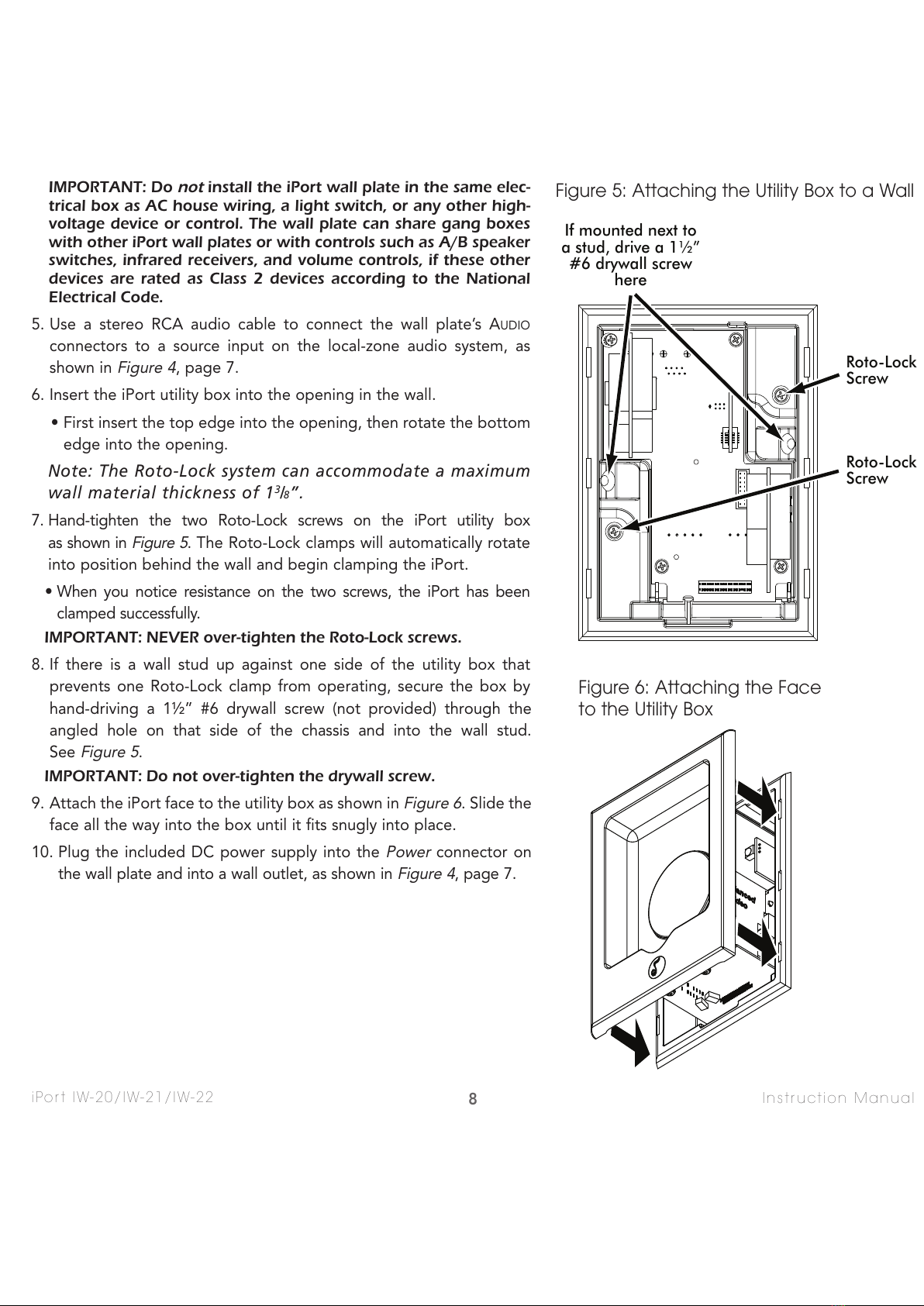
9. Hand-tighten the two Roto-Lock screws on the iPort utility box as shown in
Figure 5
, on page 8. The Roto-Lock clamps will
automatically rotate into position behind the wall and begin clamping the iPort.
• When you notice resistance on the two screws the iPort has been clamped successfully.
IMPORTANT: NEVER over-tighten the Roto-Lock screws.
10. If there is a wall stud up against one side of the utility box that prevents one Roto-Lock clamp from operating, secure the
box by hand-driving a 1½” #6 drywall screw (not provided) through the angled hole on that side of the chassis and into
the wall stud. See
Figure 5
, page 8.
IMPORTANT: Do not over-tighten the drywall screw.
11. Confirm that the switches for the Selectable Features are set in the correct positions (see
Selectable Features
, on
page 4). In particular, make sure that the Default Control Mode switch is set in the
Dis
(general) control position.
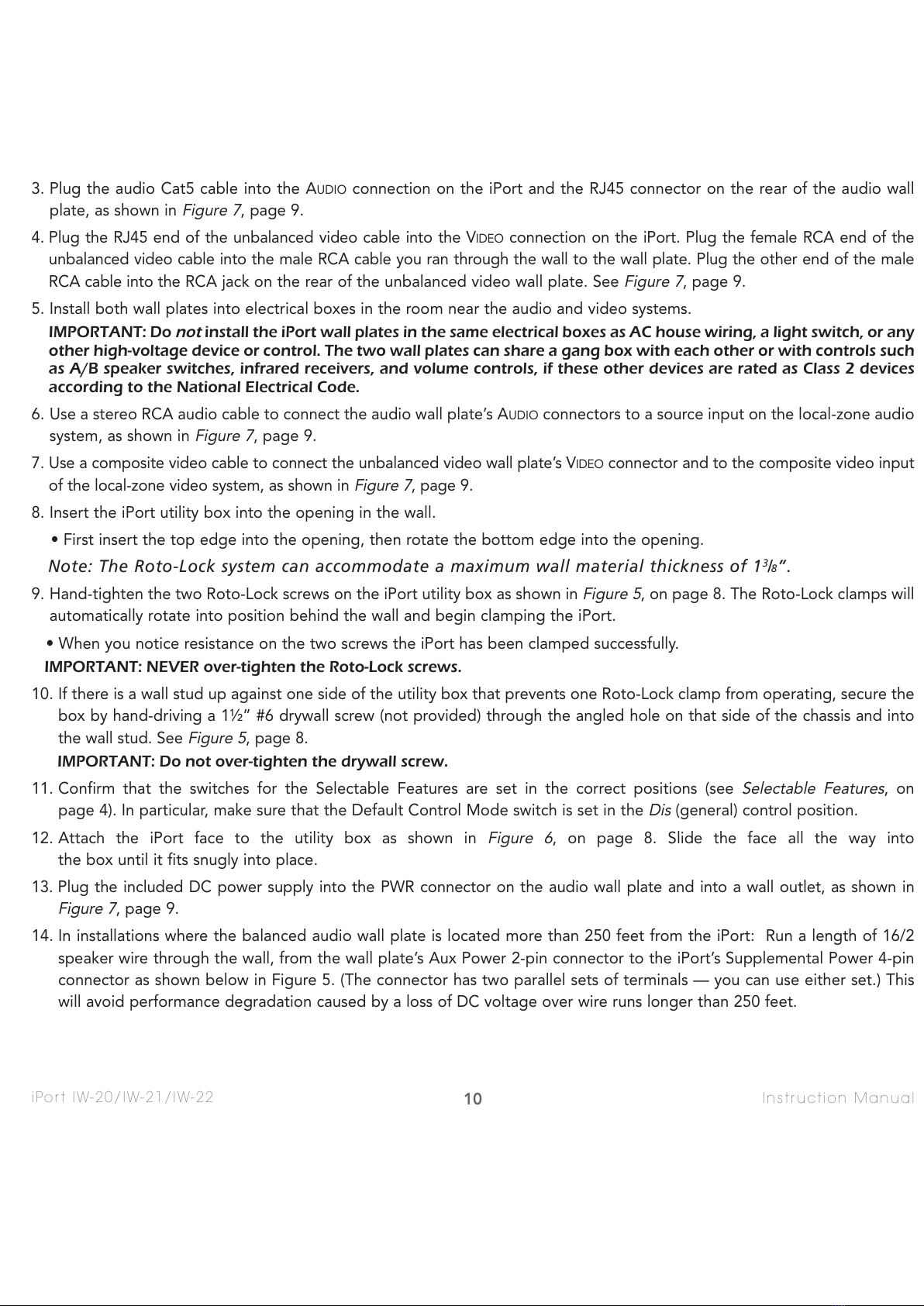
12. Attach the iPort face to the utility box as shown in
Figure 6
, on page 8. Slide the face all the way into
the box until it fits snugly into place.
13. Plug the included DC power supply into the PWR connector on the audio wall plate and into a wall outlet, as shown in
Figure 7
, page 9.
14. In installations where the balanced audio wall plate is located more than 250 feet from the iPort: Run a length of 16/2
speaker wire through the wall, from the wall plate’s Aux Power 2-pin connector to the iPort’s Supplemental Power 4-pin
connector as shown below in Figure 5. (The connector has two parallel sets of terminals — you can use either set.) This
will avoid performance degradation caused by a loss of DC voltage over wire runs longer than 250 feet.
10
All manuals and user guides at all-guides.com

11
iPort IW-20/IW-21/IW-22 Instruction Manual
iPort IW-22: Installing the Balanced Audio and RS-232 Circuit Cards
The iPort IW-22 is shipped from the factory with the appropriate balanced audio and RS-232 control circuit cards included in
the box, but
THEY ARE NOT INSTALLED IN THE IPORT’S BACKPLANE PCB
. For these functions to work, you must install
these cards into the iPort’s backplane circuit board
BEFORE
installing the iPort into a wall.
Before beginning, locate the two circuit cards in the iPort box.
• The Balanced Audio circuit card is
WHITE
.
• The RS-232 control circuit card is
BLUE.
Use care when handling the circuit cards:
• Avoid squeezing or bending any of the electronic components mounted on the cards.
• Do not force the cards into their connectors. They will only fit into the connectors one way.
• Be sure to insert the cards all the way into their connectors.
Installing the Balanced Audio Circuit Card
1. Locate the balanced audio PCB Connector and BALANCED/UNBALANCED audio switch on the iPort backplane circuit board
(see
Figure 8a
). The backplane circuit board is red, and it is located at the rear of the iPort chassis utility box.
2. Slide the BALANCED/UNBALANCED audio switch UP to the
Balanced
position (see
Figure 8b
).
NOTE: The balanced audio circuit card cannot be installed unless the switch is in the Balanced position.
3. Carefully insert the balanced audio circuit card all the way into the balanced audio PCB connector (see
Figure 8c
).
Note: The circuit card will only fit into the connector one way. Although the circuit card fits somewhat
loosely, when the iPort face is inserted into the utility box it holds the card in place.
Slide Switch
UP
Balanced Audio
PCB Connector
Balanced/Unbalanced
Audio Switch
Insert Balanced
Audio PCB Card
A BC
Figure 8: Installing the Balanced Audio Circuit Card
All manuals and user guides at all-guides.com
all-guides.com

12
iPort IW-20/IW-21/IW-22 Instruction Manual
Installing the RS-232 Circuit Card
1. Locate the RS-232 PCB connector on the iPort backplane circuit board (see
Figure 9a
). The backplane circuit board is red,
and it is located at the rear of the iPort chassis utility box.
2. Carefully insert the RS-232 circuit card all the way into the RS-232 PCB connector (see
Figure 9b
).
Note: The circuit card will only fit into the connector one way. Although the circuit card fits somewhat
loosely, when the iPort face is inserted into the utility box it holds the card in place.
iPort IW-22 Connections and Installation
See
Figure 10
, page 13
1. Before making connections, run a length of Cat5 cable through the wall from the iPort location to the balanced audio wall
plate location, and run a standard male-to-male RCA cable through the wall from the iPort location to the unbalanced video
wall plate location, as shown in
Figure 10
, page 13. The balanced audio wall plate can be located up to 500 feet from the
iPort; the unbalanced video wall plate can be located up to 30 feet from the iPort.
• Find a location for the balanced audio wall plate that is near the audio system, control systems, and a source of AC power..
• Find a location for the unbalanced video wall plate that is near the local-zone video system.
2. Install RJ-45 connectors on both ends of the audio Cat5 cable as explained in the
Wiring Cat5/RJ-45 Cables
section on
page 6.
The balanced audio Cat5/RJ-45 cable pin assignment is: The RS-232
RS-232
PCB Connector
Insert RS-232
PCB Card
AB
Figure 9: Installing the RS-232 Circuit Card
Pin 1: Data Receive
Pin 2: Data Transmit
Pin 3: Audio Left +
Pin 4: Audio Left –
Pin 5: Audio Right +
Pin 6: Audio Right –
Pin 7: Ground
Pin 8: +15V
All manuals and user guides at all-guides.com

13
iPort IW-20/IW-21/IW-22 Instruction Manual
3. Plug the audio Cat5 cable into the AUDIO connection on the iPort and the RJ45 connector on the rear of the audio/IR wall
plate, as shown in
Figure 10
.
4. Plug the RJ45 end of the unbalanced video cable into the VIDEO connection on the iPort. Plug the female RCA end of the
unbalanced video cable into the male RCA cable you ran through the wall to the wall plate. Plug the other end of the male
RCA cable into the RCA jack on the rear of the unbalanced video wall plate. See
Figure 10
.
To Video
Wall Plate
Supplemental Power
GND
+15V
GND
+15V
VIDEO
RS 232
AUDIO
IR
PWR
C
AT
5/RJ-45 C
ABLE
(
UP
TO
500
FEET
—
NOT
INCLUDED
)
RJ-45
Video
Connector
RJ-45
Audio
Connector
To RJ-45
Connector on
Wall Plate
Rear
To A
UDIO
Connectors
To RS-232
Connector
To V
IDEO
Connector
To
Composite
Video Input
To PWR Connector
S
TEREO
RCA C
ABLE
(
NOT
INCLUDED
)
C
OMPOSITE
V
IDEO
C
ABLE
(
NOT
INCLUDED
)
To
Wall Outlet
To
Control System
IR Output
To
Control System
RS-232 Output
iPort (rear) iPort
Balanced
Audio
Wall Plate
iPort
Unbalanced
Video
Wall Plate
Power
Supply
Audio System
Local-Zone Video System
3.5
MM
C
ABLE
(
NOT
INCLUDED
)
RS-232 C
ABLE
(
INCLUDED
)
To IR Connector
To RCA
Connector on
Wall Plate
Rear
U
NBALANCED
V
IDEO
C
ABLE
(
INCLUDED
)
M
ALE
-
TO
-M
ALE
RCA C
ABLE
(
UP
TO
30
FEET
,
NOT
INCLUDED
)
Supplemental
Power Connector
(see Step 6,
on page 14)
A.C. ON
AUTO ON
LRLRLRLR
1 – 2 3 – 4 5 – 6 7 – 8
PROTECTION
BBE ON
ACTIVE
ACTIVEPOWER
Figure 10: iPort IW-22 System Connections
All manuals and user guides at all-guides.com

14
iPort IW-20/IW-21/IW-22 Instruction Manual
5. Before mounting the balanced audio wall plate into its electrical
box be sure the IR/RS-232 control switch is in the RS-232 position
(see
Figure 11
). IMPORTANT: The switch must be in the RS-232
position,
even if the system will only be using IR control
.
6. For installations where the balanced audio wall plate is located more
than 250 feet from the iPort: Run a length of 16/2 speaker wire through
the wall from the wall plate’s AUX POWER connector to the iPort’s
SUPPLEMENTAL POWER connector as shown below in
Figure 12
. (The
SUPPLEMENTAL POWER connector has two parallel sets of terminals — you can
use either set.) This will avoid performance degradation caused by a loss of
DC voltage over Cat5 wire runs longer than 250 feet.
7. Install the wall plates into electrical boxes in the rooms near the audio and
video systems.
IMPORTANT: Do
not
install the iPort wall plates in the same electrical
boxes as AC house wiring, a light switch, or any other high-voltage
device or control. The two wall plates can share a gang box with each
other or with controls such as A/B speaker switches, infrared receivers,
and volume controls, if these other devices are rated as Class 2 devices
according to the National Electrical Code.
8. Use a stereo RCA audio cable to connect the balanced audio wall plate’s
AUDIO connectors to a source input on the audio system, as shown in
Figure 10
, page 13.
9. For IR control systems: Use a 3.5mm cable (mono or stereo) to connect the
balanced audio wall plate’s IR connector to the IR control output of a com-
patible IR control system. (Please go to iportmusic.com for a complete list
of compatible control systems.)
10. For RS-232 control systems: Use the supplied RS-232 cable to connect
the balanced audio wall plate’s RS-232 connector to the control output of
a compatible control system, as shown in
Figure 10
, page 13. The wall
plate RS-232 connector pinout is:
For complete information about RS-232 connections, programming, and
operation go to iportmusic.com.
11. Use a composite video cable to connect the unbalanced video wall plate’s
VIDEO connector to the composite video input of the local-zone video sys-
tem, as shown in
Figure 10
, page 13.
Set to RS-232
Position
Audio/IR Wallplate
IR/RS-232
Control
Switch
Figure 11: Wall Plate
IR/RS-232 Control Switch
Supplemental Power
GND
+15V
GND
+15V
To Au dio
Wall Plate
To Vid eo
Wall Plate
GND
+15V
GND
+15V
GND
+15V
Supplemental Power
Balanced Audio Wall Plate
(side view)
iPort
(rear view)
iPort
S
UPPLEMENTAL
P
OWER
Connection
Wall Plate
A
UX
P
OWER
Connection
16/2
Speaker
Wire
Figure 12: Supplemental Power
Connection
Pin 1: PC RX
Pin 2: GND
Pin 3: GND
Pin 4: PC TX
Pin 5: PC RX
Pin 6: Unused
All manuals and user guides at all-guides.com

15
iPort IW-20/IW-21/IW-22 Instruction Manual
12. Insert the iPort utility box into the opening in the wall.
• First insert the top edge into the opening, then rotate the bottom edge into the opening.
Note: The Roto-Lock system can accommodate a maximum wall material thickness of 13/8”.
13. Hand-tighten the two Roto-Lock screws on the iPort utility box as shown in
Figure 5
, page 8. The Roto-Lock clamps will
automatically rotate into position behind the wall and begin clamping the iPort.
• When you notice resistance on the two screws, the iPort has been clamped successfully.
IMPORTANT: NEVER over-tighten the Roto-Lock screws.
14. If there is a wall stud up against one side of the utility box that prevents one Roto-Lock clamp from operating, secure the
box by hand-driving a 1½” #6 drywall screw (not provided) through the angled hole on that side of the chassis and into
the wall stud. See
Figure 5
, page 8.
IMPORTANT: Do not over-tighten the drywall screw.
15. Confirm that the switches for the Selectable Features are set in the correct positions (see
Selectable Features
,
page 4), and attach the iPort face to the utility box as shown in
Figure 6
, page 8. Slide the face all the way into
the box until it fits snugly into place.
16. Plug the included DC power supply into the PWR connector on the wall plate and into a wall outlet, as shown in
Figure
10
, page 13.
Adjusting the iPort for Different iPod Models
The iPort is compatible with most dockable iPods including 4th Generation
and newer iPod models, iPod touch, and iPhones, including iPhone 3G. iPod
features change often. For updated compatibility visit iportmusic.com.
• To adjust the iPort for smaller iPod models, extend the iPort’s center disc
forward by rotating it counter-clockwise until you feel the detent
(see
Figure 13
). Spring-loaded clamps at the bottom of the iPort well will
hold smaller models in place.
• When switching back to larger iPod models, retract the iPort’s center
disc backwards by rotating it clockwise until you feel the detent
(see
Figure 13
). When these larger models are placed in the iPort well the
spring-loaded clamps will rotate out of the way.
For
Larger
iPod Models
For
Smaller
iPod Models
ROTATE
DISC
Figure 13: Adjusting the iPort for
Different iPod Models
All manuals and user guides at all-guides.com

16
iPort IW-20/IW-21/IW-22 Instruction Manual
Controlling the iPod in an iPort System
IW-20 Systems
• The iPod/iPhone can be controlled from its own front panel.
IW-21 Systems
• The iPod/iPhone can be controlled from its own front panel
• iPod/iPhone audio functions can also be controlled by an optional iPort IR remote (part number 70030 — black, 70032 —
white). The following functions can be controlled via IR: volume up/down, play, pause, next track/fast-forward, previous
track/fast-rewind, mute, next/previous album, playlist and chapter, repeat, and shuffle.
• The optional RS-232 Control Upgrade Kit (part number 70012) enables two-way control of the iPod/iPhone from compati-
ble control systems, along with communication of iPod metadats to the control system. (Note: Requires optional Balanced
Audio Upgrade Kit, part number 70130.) For complete information about RS-232 programming and operation, go to iport-
music.com.
IW-22 Systems:
• The iPod/iPhone can be controlled from its own front panel.
• iPod/iPhone audio functions can also be controlled by an optional iPort IR remote (part number 70030 — black, 70032 —
white). The following functions can be controlled via IR: volume up/down, play, pause, next track/fast-forward, previous
track/fast-rewind, mute, next/previous album, playlist and chapter, repeat, and shuffle.
• Extensive long-distance control of the iPod/iPhone from a compatible IR control system is also available through the IR
connector on the balanced audio wall plate. (Go to iportmusic.com for a complete list of compatible control systems.)
• Extensive two-way long-distance communication and control of the iPod/iPhone is also available from compatible RS-232
control systems. For complete information about RS-232 programming and operation, go to iportmusic.com.
IR Control Notes:
• iPort IR codes for universal remotes can be downloaded from iportmusic.com. At press time supported formats are:
RTI, Phillips Pronto style, Universal Electronics (UEI), and Universal Remote. Check iportmusic.com for the most up-to-date
information.
• For iPort remote control commands, please see the instruction manual accompanying the remote.
RS-232 Control Notes:
• When the RS-232 control mode is active, the controls on the iPod/iPhone will not operate (the iPod interface is disabled).
• When the RS-232 control mode is active, the iPod will only respond to the following IR control codes: Volume up/down,
play/pause, next track, previous track.
• iPod photo features cannot be controlled in the RS-232 control mode. The iPod must be placed in the general control mode.
The photo features can then be controlled from the iPod’s front panel controls. The iPod must be put back into the RS-232
control mode to control other functions.
All manuals and user guides at all-guides.com
all-guides.com

17
iPort IW-20/IW-21/IW-22 Instruction Manual
• When the RS-232 control mode is active, if the iPod is placed in the dock while in the
Play
mode, it will automatically
enter the
Pause
mode. The installer or programmer may wish to set the RS-232 control system to automatically send a
Play
command to return the iPod to the last playing song when it is inserted in the dock. For RS-232 commands and
programming information, please go to iportmusic.com.
iPort Status Indication (IW-21/IW-22 only)
The logo on iPort IW-21 and IW-22 front panels serves as a Status Indicator (see
Figure 14
).
Factory Default Settings:
• When the iPort is first installed and powered-up, the indicator illuminates
DIM* for 2 minutes, then turns OFF.
• When an iPod is docked in the iPort, the indicator illuminates BRIGHT* for
2 minutes, then turns OFF.
• When the iPod is un-docked from the iPort, the indicator illuminates DIM*
for 2 minutes, then turns OFF.
* The user can change these settings to any of three illumination
levels (bright, medium, and dim) via RS-232 or the iPort remote.
Always ON Mode: The installer or user can defeat the 2-minute turn-off
function (the indicator will operate as above, but will not turn OFF after two
minutes) via RS-232 or the iPort remote.
Always OFF Mode: The installer or user can turn the indicator OFF in all
modes via RS-232 or the iPort remote.
Note: If power to the iPort is lost or the power supply is disconnected, the Status Indicator will return to the
factory default settings.
Specifications
Frequency Response: 20Hz – 20kHz (±0.25dB) @ 500 ft. Cat5
THD+Noise: < 0.015%, 20Hz – 20kHz @ 500 ft. Cat5
Signal to Noise: > 90dB (A wtd.) @ 500 ft., Cat5
Maximum signal input: 1.5V RMS
Power supply: 12 ~ 15V DC, regulated
Dimensions (W x H x D): 4¾” x 65/16” x 3½” (121mm x 160mm x 89mm)
Cut-out Dimensions (W x H): 4” x 59/16” (102mm x 141mm)
Status
Indicator
Figure 14: iPort Status Indicator
All manuals and user guides at all-guides.com

18
iPort IW-20/IW-21/IW-22 Instruction Manual
LIMITED ONE (1) YEAR WARRANTY
iPort warrants to the first end-user purchaser that this iPort-brand product (“Product”), when purchased from and installed by
an authorized iPort Dealer/Distributor, will be free from defective workmanship and materials in the initial installation for the
period stated below. iPort will at its option and expense during the warranty period, either repair the defect or replace the
Product with a new or remanufactured Product or a reasonable equivalent at no charge for parts, labor and return shipping.
EXCLUSIONS
TO THE EXTENT PERMITTED BY LAW, THE WARRANTY SET FORTH ABOVE IS IN LIEU OF, AND EXCLUSIVE OF, ALL OTHER
WARRANTIES, EXPRESS OR IMPLIED, AND IS THE SOLE AND EXCLUSIVE WARRANTY PROVIDED BY IPORT. ALL OTHER
EXPRESS AND IMPLIED WARRANTIES, INCLUDING THE IMPLIED WARRANTY OF MERCHANTABILITY, IMPLIED
WARRANTY OF FITNESS FOR USE, AND IMPLIED WARRANTY OF FITNESS FOR A PARTICULAR PURPOSE ARE
SPECIFICALLY EXCLUDED. No one is authorized to make or modify any warranties on behalf of iPort.
The warranty stated above is the sole and exclusive remedy and iPort’s performance shall constitute full and final satisfaction
of all obligations, liabilities and claims with respect to the Product. IN ANY EVENT, IPORT SHALL NOT BE LIABLE FOR
CONSEQUENTIAL, INCIDENTAL, ECONOMIC, PROPERTY, BODILY INJURY, OR PERSONAL INJURY DAMAGES ARISING
FROM THE PRODUCT, ANY BREACH OF THIS WARRANTY OR OTHERWISE.
This warranty statement gives you specific legal rights, and you may have other rights which vary from state to state. Some
states do not allow the exclusion of implied warranties or limitations of remedies, so the above exclusions and limitations may
not apply. If your state does not allow disclaimer of implied warranties, the duration of such implied warranties is limited to
the period of iPort’s express warranty.
______________________________________________________________________________
Your Product Model and Description: iPort IW-20, IW-21, IW-22
Warranty Period for this Product: One (1) year from the date on the original sales receipt, invoice or other satisfactory proof
of purchase.
Additional limitations and Exclusions From Warranty Coverage: The warranty described above is non-transferrable, and does
not include damage to allied or associated equipment which may result for any reason from use with this Product, and does
not include Product failure caused by accident, disaster, negligence, improper installation, misuse (e.g. overdriving the
amplifier or speaker, excessive heat or cold or humidity, outdoor installation), or from service or repair which has not been
authorized by iPort.
Obtaining Authorized Service: If you purchased your iPort from an iPort Dealer, you (1) must contact your authorized iPort
Dealer/Installer or call iPort Customer Service at (800) 582-0772 within the warranty period, (2) must obtain a return merchan-
dise number (RMA), and (3) deliver the Product to iPort shipping prepaid during the warranty period, together with the orig-
inal sales receipt, invoice or other satisfactory proof of purchase from your iPort Dealer. If you did not purchase from an iPort
dealer, you must contact your authorized seller within the warranty period and obtain instructions for obtaining authorized
service.
All manuals and user guides at all-guides.com

19
iPort IW-20/IW-21/IW-22 Instruction Manual
Notes:
All manuals and user guides at all-guides.com

san clemente ca | 888 .45 . iPort | www.iportmusic.com
33-5191 061509aFinal
©2009 Dana Innovations. All rights reserved.
iPort and Roto-Lock are registered trademarks of Dana Innovations. iPod and iPhone are trademarks or registered trademarks of Apple Inc.
Due to continuous product improvement, all specifications are subject to change without notice.
For the latest iPort product information go to
www.iportmusic.com
All manuals and user guides at all-guides.com
This manual suits for next models
2
Table of contents