Danntech Eco-Line GB-SE/IA-IA/C User manual

Filename: Eco-Line_Signal_Converters_User_Manual.docx 02 May 2020
Version: 1.17
©danntech – PROCESS INSTRUMENTATION Page 1 of 22
Eco-Line Signal Converters User Manual
The Eco-Line range of signal converters has been designed using a low-cost, powerful microprocessor
which enables us to offer flexibility, reliability and accuracy at a really good price in a small package.
Using miniature DIP switches, a variety of standard inputs and outputs can be
selected and with the ‘one button’ calibration, accurate operation in any
configuration is assured. Having selected the required input and output ranges,
these can be adjusted to be anything within the selected range using the ‘one
button’ calibration.
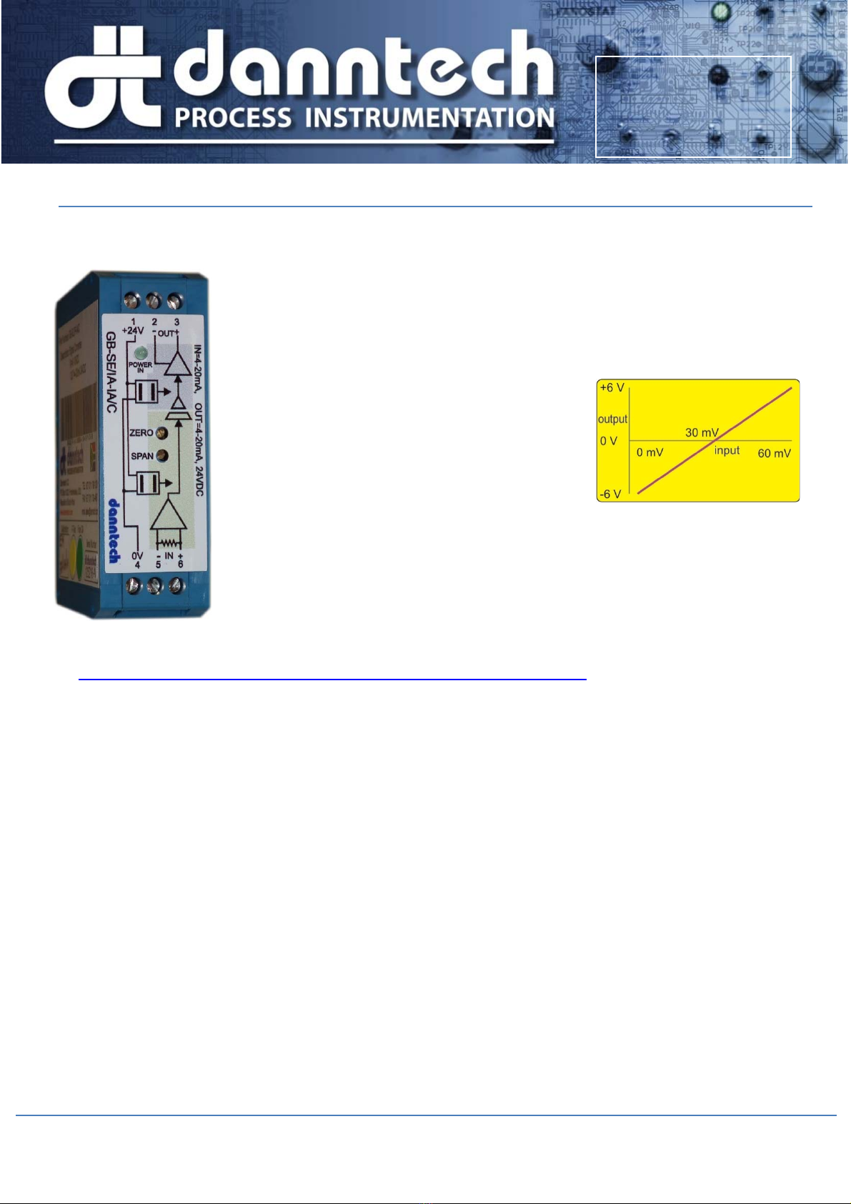
For example, with a 0 to 100 mV input and ±10V
output selected, one can calibrate the device to
have say 0 to 60 mV input where 30 mV input gives
an output of 0 V, 60 mV an output of +6 V and for
0 mV input and output of – 6 V. Output inversion is
also easily accommodated.
The Zero and Span trimpots can be disabled or switched to a wider adjustment
range using the DIP switches. Filtering is also DIP switch selectable in four ranges
up to 60 seconds.
We can also make firmware changes if you have a special application that we have
not catered for.
If you have any comments or suggestions which could improve this User Manual please e-mail them to me
at mailto:[email protected]?subject=Eco-Line User Manual - Comment.
Configuration ................................................. 2
How it Works ................................................. 4
Quick Configuration Guide ............................ 5
DIP Switches Push Button (PB) and Push
Button Link .................................................... 8
Input Range Selection ................................... 9
Input Setup: ................................................... 9
Output Range Selection .............................. 10
Output Setup ............................................... 10
Test Mode ................................................... 12
DIP SW1 Operational Settings .................... 14
Power Up .................................................... 16
Application Examples .................................. 16
Typical Results ........................................... 16
Other Eco-Line Versions ............................. 17
Using the Eco-Line Signal Converter as a
Preset Signal Source .................................. 17
Serial Communications ............................... 17
Setting up without a Process Signal Calibrator
................................................................... 18
Opening the Enclosure ............................... 19
Some other interesting things about the Eco-
Line Signal Converters ............................... 20
Specifications ............................................. 21
Part Numbering .......................................... 22
Danntech makes no warranty of any kind with regard to this material, including, but not limited to, the implied warranties of merchantability and fitness for a particular
purpose. Danntech shall not be liable for errors contained herein or for incidental or consequential damages in connection with the furnishing, performance or use of this
material. This document contains proprietary information, which is protected by copyright. No part of this document may be photocopied, reproduced, or translated into
another language without the prior written consent of Danntech. The information in this document is subject to change without notice.
©danntech 2020
www.danntech.com
www.danntech.co.za
www.danntech.biz

Filename: Eco-Line_Signal_Converters_User_Manual.docx 02 May 2020
Version: 1.17
©danntech – PROCESS INSTRUMENTATION Page 2 of 22
Configuration
As a customer you can do one of the following:
A: Order the standard stock part you require from this list
below:
1. GB-SE/IA-IA/C Input: 4-20 mA; Output: 4-20 mA;
Auxiliary Supply: 24 VDC
2. GB-SE/VA-IA/C Input: 0-10 V; Output: 4-20 mA; Auxiliary Supply: 24 VDC
3. GB-SE/IA-VA/C Input: 4-20 mA; Output: 0-10 V; Auxiliary Supply: 24 VDC
4. GB-SE/RE-IA/C Input: 0-5 kΩ mA; Output: 4-20 mA; Auxiliary Supply: 24 VDC
(we may add others here depending upon demand)
and then accept our standard configuration –
Zero and Span Trimpots enabled,
Zero and Span Normal Range Adjustment Select, and
Moving Average Filter Step Response Time = 1 second.
No further configuration is required from you and you can ignore the remainder of this User
Manual.
Or
B: Order the exact part you require using our Eco-Line Part Signal Converter Part Numbering
guide and fill in the Eco-Line Ordering Form, sign and send to us and we will configure them
for you.
No further configuration is required from you and you can ignore the remainder of this User
Manual.
Or
C: Order the User Configurable Version (UCV) and then you can configure it yourself using the
Eco-Line Signal Converter User Manual (this manual).
You will not be able to configure certain versions as some hardware changes are required
for some types.
User configuration can be done for the following ranges:
Inputs: 0-100 mV, 0-1 V, 0-10 V, 0-100 V, ±100 mV, ±1 V, ±10 V, ±100 V, 0 to 22 mA
Outputs: 0-100mV, 0-1V, 0-10V, ±10 V, 0 to 22 mA
The User Configurable Version provides a way to configure the device for non-standard inputs and

Filename: Eco-Line_Signal_Converters_User_Manual.docx 02 May 2020
Version: 1.17
©danntech – PROCESS INSTRUMENTATION Page 3 of 22
outputs within any of the configuration ranges listed above.
For example, you can set up the input to be say 200 mV to 800 mV with the
output 20 to 4 mA (inversion).
For 200 mV input you want 20 mA output, and
800 mV input you need 4 mA output.
The Eco-Line Signal Converter provides a way of
doing this without the need for you to have an
expensive Process Calibrator to simulate the
required input voltage.
All you will need is a basic, accurate, multi-meter
and you can use the Eco-Line Signal Converter
itself to generate the required input signal range
(or you can use a process signal calibrator if you have one).
Please note that the product version you receive may not exactly match this
picture as we plan to add a few more features early in 2013. These are: Alarm and Input Status
LED operation and serial communications.
When you change the input or output ranges you must recalibrate the input and output as
exact analogue values are slightly different internally for each range.
The DIP switches, Push Button Link and setup LEDs are accessed by removing the covering
stickers.
Input
(
mV
)
Output
(
mA
)
200 20.0
500 12.0
800 4.00

Filename: Eco-Line_Signal_Converters_User_Manual.docx 02 May 2020
Version: 1.17
©danntech – PROCESS INSTRUMENTATION Page 4 of 22
HowitWorks
A microcontroller forms the central part of the signal converter and after some basic signal conditioning the
analogue signal is digitized. The Input Signal Conditioning is done in four stages and the various gain and
offsets are applied to the input signal.
The design includes a programmable current source and voltage reference. These are not available for the
user to access but will be used in our resistance input devices. An optional thermocouple amplifier and cold
junction temperature sensor are also included for later use.
Galvanic isolation between input, output and power supply is provided using to high quality DC to DC
converters with the requisite noise filtering.
DIP switch 1 (SW1) provides selection inputs to the microcontroller, DIP switch 2 (SW2) switches the
various analogue circuit parts to provide the signal conditioning necessary for the various input options. DIP
switch 3 (SW3) selects the various output circuit options.
We have also included an optional, isolated RS232/TTL interface which will be used in later versions for
configuration purposes, data logging and is able to be used for CANBUS.

Filename: Eco-Line_Signal_Converters_User_Manual.docx 02 May 2020
Version: 1.17
©danntech – PROCESS INSTRUMENTATION Page 5 of 22
QuickConfigurationGuide
If you change the input or output ranges from the settings as delivered (input: 4-20 mA,
output: 4-20 mA) you must redo the setup for the changes made. So if you change the
input, then only the input needs to be redone, not the output, likewise for the output. The
exact internal analogue values are slightly different for
each range.
This step by step procedure will use, as an example, the setup
for an Eco-Line Signal Converter with an input of
2.0 mA to 18.0 mA and output of 1.0 V to 5.0 V.
We will assume that you have a Process Calibrator to inject the desired input range although you
could use the Eco-Line to generate the mA signal for you.
(In the case where you wish to use the Eco-Line to
generate the input signal you will need to first of all set
up the output to be 2.0 to 18 mA – follow the Output
Setup procedure. Then you connect the output to the
input and then set up the input using a multi-meter to
check and adjust the input. Having done that you, then
redo the setup for output to be what you require)
Normally the Eco-Line UCV version will be delivered
with input and output set to be 4 to 20 mA.
Remove the DIP switch covering stickers (we do supply
spare covering stickers with the unit).
Using the table in the “Input Range Selection” section
use DIP Switch SW2 select the input range of
4-20 mA (this is how it is normally delivered) so
switches 2, 3 and 8 must be ON all others OFF.
Use DIP Switch SW3 to select an output of 0 to
10 V. From the table in the “Output Range Selection”
you will see that SW3 must have switches 2 and 6 ON
and all others OFF. (The device is normally delivered set up for 4-20 mA output, which is SW3 only
1 and 6 are ON).
At this point you can decide if you wish to have:
the Zero and Span trimpots enabled (use SW1
switch 1 to do this OFF=disabled, ON=enabled).
the Zero and Span set for Normal or Wide range
adjustment (use SW1 switch 2 to do this
OFF=normal ±10%, ON=wide ±50%).
The filtering you desire (using SW1 switches 3
and 4 – switch 4 ON and 3 OFF = 1 second, for
other selections see the table).
Input
(
mA
)
Output
(
V
)
2.0 1.0
10.0 3.0
18.0 5.0

Filename: Eco-Line_Signal_Converters_User_Manual.docx 02 May 2020
Version: 1.17
©danntech – PROCESS INSTRUMENTATION Page 6 of 22
Now you can set up the input:
1. Now refer to the table in the section “DIP SW1 Operational Settings on page 14” to set up
the input – switch SW1 switch 5 ON to select the Input Calibration mode (switches 6, 7 and
8 must be OFF).
2. Now using your Process Calibrator, inject the minimum input value (2 mA in this case). The
state of SW3 does not matter at this point.
3. Now you need to press and hold in the Push Button (you can do this from the front panel or
by closing the PB link next to DIP switch SW1). Hold in until the Push Button until the Red
Configuration LED comes on.
4. The Green Configuration LED (as well as the Status LED) will come on for about 1 second
to indicate that the minimum input value has been captured. Release the button as soon as
the RED Configuration LED comes on.
(During the minimum input calibration stage the unit will output a value set by the Zero
trimpot which can be used for input calibration if required)
5. Now inject the maximum input value and again press and hold the Push Button as before to
capture the maximum input value.
The internal processor has now recorded and saved these values to use forever.
Switch SW1 switch 5 off to complete the input calibration.
Now you can set up the output:
Here you have two choices of how to drive the output – you can
use the input, with your Process Signal Calibrator (DIP SW1
switch 6=OFF) or the ZERO and SPAN trimpots (DIP SW1
switch 6=ON).
1. Now refer to the table in the section “DIP SW1 Operational Settings on page 14” to set up
the output – switch SW1 switch 7 ON to select the Output Calibration mode (switch 5 and 8
must be OFF).
2. Set DIP SW1 switch 6 to choose your output control -
OFF=uses the input;
ON=uses the ZERO and SPAN trimpots, (ZERO for minimum output value, SPAN for
maximum output value) – this is recommended.
3. Now using your Process Calibrator (or the ZERO trimpot) set the output to produce the
minimum output value (1 V in this case).
4. Now you need to press and hold in the Push Button (you can do this from the front panel or
by closing the PB link next to DIP switch SW1). Hold in the Push Button until the Red
Configuration LED comes on.
5. The Green Configuration LED (as well as the Status LED) will come on for about 1 second

Filename: Eco-Line_Signal_Converters_User_Manual.docx 02 May 2020
Version: 1.17
©danntech – PROCESS INSTRUMENTATION Page 7 of 22
to indicate that the minimum output value has been captured. Release the button as soon
as the RED Configuration LED comes on.
6. Now using your Process Calibrator (or the SPAN trimpot) set the output to produce the
maximum output value (5 V in this case).
7. Again press and hold the Push Button as before to capture the maximum output value.
The internal processor has now recorded and saved these values to use forever.
Switch SW1 switch 7 (and switch 6 if used) off to complete the output calibration.
It is not necessary to setup both the Input and Output, you only need to setup those which have
been changed, they operate independently from each other.
If you are using the Zero and Span trimpots (SW1 switch 1 is ON), you will need to inject the
minimum and maximum inputs and adjust the Zero and Span trimpots to give the exact outputs
you require. Do this once to set and a second time to check – for best accuracy.

Filename: Eco-Line_Signal_Converters_User_Manual.docx 02 May 2020
Version: 1.17
©danntech – PROCESS INSTRUMENTATION Page 8 of 22
DIPSwitchesPushButton(PB)andPushButtonLink

Filename: Eco-Line_Signal_Converters_User_Manual.docx 02 May 2020
Version: 1.17
©danntech – PROCESS INSTRUMENTATION Page 9 of 22
InputRangeSelection
Setup using DIP Switch (SW2) and J1 –
(J1 is a solder link accessible only by opening the enclosure, you will need to open the enclosure,
see on page 18 and solder a blob of solder on the pads to close this link):
DIP Switch
SW2 # 1 2 3 4 5 6 7 8
Input
4-20mA OFF ON ON OFF OFF OFF OFF ON
0-20mA OFF ON ON OFF OFF OFF OFF ON
0-100mV OFF OFF ON OFF OFF OFF OFF OFF
0-1V OFF ON ON OFF OFF OFF OFF OFF
0-10V ON OFF ON OFF OFF OFF ON OFF
0-30V
(J1 in) OFF OFF ON OFF OFF OFF ON OFF
0-100V OFF ON ON OFF OFF ON OFF OFF
±10V OFF OFF OFF ON OFF OFF ON OFF
InputSetup:
This is done with the following steps – injecting minimum and maximum values:
1. SW1-5 is used to activate input calibration mode. SW1-6, 7 & 8 must all be off. The green LED
will flash twice every 2 seconds.
2. Inject the minimum input you require.
3. Press and hold the Push Button (PB) for a few seconds until the red LED flashes and the green
LED stays on for approximately two seconds. Release the Push Button as the red LED flashes,
this latches the input value as the minimum input calibration value. The green LED will now
flash as follows:
4. Inject the maximum value.
5. Press and hold the Push Button (PB) until the red LED flashes and the green LED stays on for
approximately one second. Release the Push Button as the red LED flashes, this latches the
input value as the maximum input calibration value. The green LED will now flash as follows:

Filename: Eco-Line_Signal_Converters_User_Manual.docx 02 May 2020
Version: 1.17
©danntech – PROCESS INSTRUMENTATION Page 10 of 22
6. Switch SW1-5 off to complete input calibration process.
While doing the input calibration information can be observed using the RS232 jack socket
connection. This works at 9600, 8, N, 1 no flow control. Without the link installed between CN2
(programming header) pins 1 & 2 only the header line will be sent out (this is the way it is
delivered). To see the internal values you must have this link installed.
Typically the info displayed will be:
Eco-line Signal Converter - (dt331) Copyright Danntech 2012 Firmware V200
Input Cal Mode. Use Button to capture Input Minimum and Input Maximum
Ain=2955 VR1=3727 VR2= 857 SW1= 24 Button=0 m=1.06 c=580.20 DACOut=3737
[Your unit may not have the COMMS jack socket fitted]
OutputRangeSelection
Setup using DIP Switch (SW3):
DIP Switch
SW3 # 1 2 3 4 5 6 7 8
Output
4-20mA ON OFF OFF OFF OFF ON OFF OFF
0-20mA ON OFF OFF OFF OFF ON OFF OFF
0-5V OFF ON OFF OFF OFF ON OFF OFF
0-10V OFF ON OFF OFF OFF ON OFF OFF
±10V OFF ON ON OFF ON OFF ON OFF
OutputSetup
This is done by using either the Zero and Span trimpots, or by injecting a signal into the input to
control the output and then latching the minimum and maximum output values desired. You can
invert the output if you need this – making the maximum say =4mA and the minimum =20mA.

Filename: Eco-Line_Signal_Converters_User_Manual.docx 02 May 2020
Version: 1.17
©danntech – PROCESS INSTRUMENTATION Page 11 of 22
Use the following steps:
1. SW1-7 is used to activate output calibration mode. SW1-8 must be off. The green LED will
flash twice every 2 seconds in the following way:
2. If SW1-6 is off then the input is used to activate the output. If SW1-6 is on then the Zero and
Span trimpots are used to control the desired output (this is the recommended option).
3. If SW1-6 is on (using the ZERO trimpot to set the output) adjust VR2 (Zero) until you get the
output desired for the minimum output value.
If SW1-6 is OFF (you have selected to use the input to control the output) vary the input to
adjust the output you require for the minimum output value.
7. Press and hold the Push Button (PB) for a few seconds until the red LED flashes and the green
LED stays on for approximately two seconds. Release the Push Button as the red LED flashes,
this latches the output value as the minimum output calibration value. The green LED will now
flash as follows:
4. If SW1-6 in on (you have selected to use the SPAN trimpot to control the output) adjust VR1
(Span) until you get the output desired for the maximum output value.
If SW1-6 is off (you have selected to use the input to control the output) vary the input to adjust
the output you require for the maximum output value.
5. Press and hold the Push Button (PB) for a few seconds until the red LED flashes and the green
LED stays on for two seconds. Release the Push Button as the red LED flashes, this latches
the output value as the maximum output calibration value. The green LED will now flash as
follows:
6. Switch SW1-7 (and 6) off to complete the process.
While doing the input calibration information can be observed using the RS232 jack socket
connection. This works at 9600, 8, N, 1 no flow control. Without the link installed between CN2
(programming header) pins 1 & 2 only the header line will be sent out. To see the internal values
you must have this link installed.
Typically the info displayed will be:
Eco-line Signal Converter - (dt331
)
Copyright Danntech 2012 Firmware V200
Output Cal Mode. Use Button to capture Output Min and Max. <SW1-6 OFF=Ain, ON=POTs top=zero, bot=span>
Ain= 535 VR1=3727 VR2= 857 SW1=104 Button=0 m=1.07 c=285.11 DACOut= 857
[Your unit may not have the COMMS jack socket fitted]

Filename: Eco-Line_Signal_Converters_User_Manual.docx 02 May 2020
Version: 1.17
©danntech – PROCESS INSTRUMENTATION Page 12 of 22
TestMode
There is a test function built in which is activated by switching ON SW1-8 with switches SW1-5, 6
& 7 OFF.
In Test mode the output can be switched with each press as follows:
No press yet - following the input
1. the minimum possible output value
(which would can be 0 mA for an output setup of 4–20 mA or -0.3 V for an output setup of
0–10 V)
2. the minimum setup output value – 0 %
(which would be 4 mA for an output setup of 4–20 mA or 0 V for an output setup of 0–10 V)
3. the midrange setup output value - 50%
(which would be 12 mA for an output setup of 4–20 mA or 5 V for an output setup of
0–10 V)
4. the maximum setup output value – 100%
(which would be 20 mA for an output setup of 4–20 mA or 10 V for an output setup of
0–10 V)
5. maximum possible output value
(which would be about 21.5 mA for an output setup of 4–20 mA or 10.4 V for an output
setup of 0–10 V)
Using the Push Button (PB) you can cycle through these outputs. The cycle is repeated as the
button is pressed.
The LED will flash once every 2 seconds and the output will be as per normal, determined by the
input without the Zero and Span adjustments. The green LED will flash as follows:
First press – output = zero
Second press – output = calibrated minimum

Filename: Eco-Line_Signal_Converters_User_Manual.docx 02 May 2020
Version: 1.17
©danntech – PROCESS INSTRUMENTATION Page 13 of 22
Third press – output = (calibrated maximum – calibrated minimum)/2 + calibrated minimum
Fourth press – output = calibrated maximum
Fifth press – output = maximum
Sixth press – output = normal and follows input without Zero and Span adjustments
While doing the input calibration information can be observed using the RS232 jack socket
connection. This works at 9600, 8, N, 1 no flow control. Without the link installed between CN2
(programming header) pins 1 & 2 only the header line will be sent out. To see the internal values
you must have this link installed (the unit is shipped with this link out).
Typically the info displayed will be:
Eco-line Signal Converter - (dt331) Copyright Danntech 2012 Firmware V200
Use Button to Cycle through outputs => 0, min, (max-min)/2, max 4095
Ain= 536 VR1=3727 VR2= 858 SW1=136 Button=0 m=1.07 c=285.11 DACOut= 859 Tm=1.00 Tc=0.00 Runtime= 122
[Your unit may not have the COMMS jack socket fitted]

Filename: Eco-Line_Signal_Converters_User_Manual.docx 02 May 2020
Version: 1.17
©danntech – PROCESS INSTRUMENTATION Page 14 of 22
DIPSW1OperationalSettings
SW1 Description Default Setting
1
Zero and Span Trimpot Enable
Enables the operation of the Zero and Span trimpots on the front
panel. You can enable the trimpots, make your adjustments and
then when you disable the trimpots, the values that you last adjusted
are saved and used until the trimpots are enabled again.
OFF = trimpots disabled
ON = trimpots enabled
ON
2
Zero and Span Normal/Wide Range Adjustment Select
Provides “normal” and “wide” trimpot adjustments for Zero and
Span.
OFF = Zero and Span adjustment are normal i.e. approx ±10% over
full trimpot range.
ON = Zero and Span adjustment are “wide” i.e. approx ±50% over
trimpot range.
Note that you may need to adjust zero and span several times to get
the best accurac
y
.
OFF
3
Filtering Select
Selects the moving average filter step response time:
SW1-3 SW1-4 Filter Step Response
Time
(
seconds
)
OFF OFF No filtering – step response
approximatel
y
0.1 sec
OFF ON 1 sec
ON OFF 10 sec
ON ON 60 sec
OFF
4 ON
5
Input Calibration
Calibrates the input circuit to take into account any component
tolerances for the input range selected. Using calibrate button to
indicate the required input is present at the input. You must follow
the sequence and carry out all three steps in order. Uses three
values to fit polynomial to input calibration for highest accuracy
operation.
Inject Minimum Input Value – press and hold button until green LED
stops flashing and stays on, then release button.
Inject Maximum Input Value – press and hold button until green LED
stops flashing and stays on, then release button.
OFF
6
Output Calibration Activation Source Select
OFF = Input is selected as the output activation source.
OFF

Filename: Eco-Line_Signal_Converters_User_Manual.docx 02 May 2020
Version: 1.17
©danntech – PROCESS INSTRUMENTATION Page 15 of 22
ON = Zero and Span trimpots selected as the output activation
source for minimum and maximum output values.
7
Output Calibration
Calibrates the output circuit to take into account any component
tolerances for the input range selected and the output range
required.
Uses the calibrate button to indicate the required output is present at
the output. You must follow the sequence and carry out both steps
in order. The output can be set using the input (SW1-6 = OFF) or the
values are set using the Zero and Span trimpots
(SW1-6 = ON).
Select output activation source Ain or trimpots.
Set input or Zero trimpot for the minimum output required - press
and hold button until green LED stops flashing and stays on, then
release button.
Set input or Span trimpot for the maximum output required - press
and hold button until green LED stops flashing and stays on, then
release button.
OFF
8
Test
Built-in test function which is activated by switching on SW1-8 with
switches SW1-5, SW1-6 & SW1-7 off.
In Test mode the output can be switched in sequence from
1. following the input, to
2. minimum possible output value, to
3. a value for approximately 4mA output (if the output is set for
current, otherwise approximately 2 volts),
4. then 12 mA (50% output),
5. then 20mA (100% output) and
6. then 22mA (maximum output value)
7. then back to following the input – step 1.
Using the calibrate button you can cycle through these outputs. The
c
y
cle is repeated as the button is pressed.
OFF

Filename: Eco-Line_Signal_Converters_User_Manual.docx 02 May 2020
Version: 1.17
©danntech – PROCESS INSTRUMENTATION Page 16 of 22
PowerUp
All the LEDs flash twice on power up or when the unit resets for any reason.
On power up the following is sent to the RS232 port irrespective of the CN2 link.
Eco-line Signal Converter - (dt331
)
Copyright Danntech 2012 Firmware V200
Normal power up!
If the device has restarted due to a watchdog reset then instead of Normal power up! The following
will be displayed instead:
Eco-line Signal Converter - (dt331
)
Copyright Danntech 2012 Firmware V200
Restarted processor because of watchdog timeout!
[Your unit may not have the COMMS jack socket fitted]
ApplicationExamples
TypicalResults

Filename: Eco-Line_Signal_Converters_User_Manual.docx 02 May 2020
Version: 1.17
©danntech – PROCESS INSTRUMENTATION Page 17 of 22
OtherEco‐LineVersions
UsingtheEco‐LineSignalConverterasaPresetSignalSource
You can configure the desired output type and range for the signal that you require. Set the
maximum and minimum as per setting the Output Range Selection section. Then you set the unit
into Test Mode by switching ON SW1-8 with switches SW1-5, 6 & 7 OFF.
Now by pressing the Push Button repeatedly cycles through the five possible outputs:
At starting 0 (zero) output value
Press 1 Minimum Output Calibration value
Press 2 Halfway between Minimum and Maximum Output Calibration values
Press 3 Maximum Output Calibration value
Press 4 Full-scale possible output value
Press 5 back to starting
SerialCommunications
As delivered the communications socket is left out and connection using RS232 TTL is available
internally. This is not isolated from the input signal. We do have the facility to include an isolated
RS232 TTL using the 4 way jack socket. This will be used in the future to provide a software
configuration feature. We can also provide a configuration cable which provides connection from
USB to our RS232 TTL.

Filename: Eco-Line_Signal_Converters_User_Manual.docx 02 May 2020
Version: 1.17
©danntech – PROCESS INSTRUMENTATION Page 18 of 22
SettingupwithoutaProcessSignalCalibrator
The unit is designed to be able to be setup without a Process Signal Calibrator for standard type
inputs.
The basic process is as follows:
Set up the output to be able to generate the type of input signal you require.
Using a multi-meter adjust the trimpots to configure the output for the minimum and maximum
values you require for your input.
Now, connect up the output to the input including your multi-meter as shown in the diagram
above for voltage or current input.
Now calibrate the input and while calibrating the input the output will generate the values you
setup previously for the input minimum and maximum values.
When you have set up the input, you need to go back and configure the output to be what you
required.
This avoids the need for an expensive process signal calibrator for basic input types/ranges.

Filename: Eco-Line_Signal_Converters_User_Manual.docx 02 May 2020
Version: 1.17
©danntech – PROCESS INSTRUMENTATION Page 19 of 22
OpeningtheEnclosure
The only reasons to open the unit are to install the solder link J1 (if you need the 0-30 V input
range) or to install the CN2 link to enable the COMMS output. Both of these are fairly unusual and
most users will not need to open the unit.
Use a moderately sharp blade (not too sharp) to
gently lift up the left side of the front label. Be
careful not to cut the label. Run the blade all along
the left side to free up the left side of the front
label.
With a screwdriver you can get some
leverage at the bottom of the enclosure
between the parts as shown in the photo.
Gently pry the left side cover apart from the
front panel.
Using the screwdriver gently pry open the
enclosure all around taking care not to damage
the plastic parts

Filename: Eco-Line_Signal_Converters_User_Manual.docx 02 May 2020
Version: 1.17
©danntech – PROCESS INSTRUMENTATION Page 20 of 22
SomeotherinterestingthingsabouttheEco‐LineSignalConverters
This QR code is on the right side of the product and if you download a
barcode reader app for your smartphone and scan in this code you will be
taken to the latest version of this user manual on our website.
http://danntech.info/user_manuals/Eco-Line_Signal_Converters_User_Manual.pdf
If you squeeze the enclosure (front to back) you can press in the Push Button. So you can
get away from using a sharp thin object to press in the switch.
You can use the Eco-Line as a signal source to calibrate itself or use it to generate two
output levels which you can switch between by pressing the push button (this by using the
Input Calibration mode). You can also use the Test mode to generate five different outputs
which can be switched in sequence using the push button. See the section “Using the Eco-
Line Signal Converter as a Preset Signal Source”.
If you order our USB configuration adaptor you can install the internal CN2 link and then get
various information to a PC with a Terminal Emulation program (there are freeware versions
around). At some point we will provide a way read from and write to multiple devices using
RS232, RS485, USB or Ethernet.
If you are setting several units it may be easiest to use our
auxiliary Push Button switch which you can insert next to DIP
switch SW1, this makes it a bit easier to work with the DIP
switches while setting up. A small flat screw driver is also useful if
you are using the zero and span trimpots.
This manual suits for next models
3
Table of contents
Other Danntech Media Converter manuals
Popular Media Converter manuals by other brands

Ludlum Measurements
Ludlum Measurements 2224-1 manual

IMC Networks
IMC Networks iMcV-Giga-MediaLinX Operation manual

Audio international
Audio international MSM2911-01-x installation manual

RGBlink
RGBlink MSP 210H user manual

Net Optics
Net Optics 10 GigaBit Media Converter Tap installation guide

BARIX
BARIX Instreamer user manual