Dantel 46034 User manual
CAUTION
Install or remove modules from the shelf only when the power is off.
If you install a module in the shelf with the power on, the internal
circuitry may suffer damage and the product warranty will be void.
Remove and install circuit boards only in a static-safe environment
(use antistatic wrist straps, smocks, footwear, etc.).
Keep circuit boards in their antistatic bags when they are not in use.
Do not ship or store circuit boards near strong electrostatic, electromag-
netic, magnetic, or radioactive fields.
For more complete information on electrostatic discharge safety
precautions, refer to BellcoreTM Technical Reference #TR-NWT-000870.
Copyright 1997 by Dantel, Inc. • Dantel is a registered trademark of Dantel, Inc. • ISO 9001 Registered
Printed in the U.S.A.
INSTALLATION&OPERATION MANUAL
46034-0997<90-00030>
46034
HUBBING MODULE
About this Practice:
• This practice has been reformatted
to meet ISO 9001 requirements.
Issue date: September 1997
Reissued Practices: Updated and
new content can be identified by a
banner in the right margin.
UPDATED
Table of Contents
Ordering Information ........................................................................... 2
General Description.............................................................................. 2
Circuit Description ............................................................................... 2
Application Information ....................................................................... 6
Installation.......................................................................................... 11
Operation ............................................................................................ 16
Technical Specifications ..................................................................... 17
Warranty ............................................................................................. 18
46034-00 REV__
46034-00
HUBBING
MODULE
RX 1
RX 2
RX 3
RX 4
RX 5
RX 6
RX 7
RX 8
TX 1
TX 2
TX 3
TX 4
TX 5
TX 6
TX 7
TX 8
RXD
TXD

PAGE 2 46034-0997<90-00030>
ORDERING INFORMATION
NOTE: This section lists the different options available for this product. To order any of the avail-
able options, contact Dantel Inside Sales through our toll-free number, 1-800-432-6835.
OPTION NUMBER FEATURES
B11-46034-00 Hubbing Module
GENERAL DESCRIPTION
The 46034 Hubbing Module provides nine data ports for
digital data summing, distribution or bridging.
Each port connects through six individual communication buses.
Ports one through eight can accept data through RS-232 and
RS-422 interfaces, depending on the strapping selection. Port
nine operates with an optional on-board communications subas-
sembly. The interface type depends on the selected subassembly.
If handshaking is required with RS-232 communications, the
module can operate up to five RS-232 data ports. One of those
five RS-232 data ports is port nine, operating with a 49029
RS-232 Current Loop Interface Subassembly.
The module comes with a TTL subassembly (bypass card) that
allows port nine to function as a TTL data bus interface in the
absence of a subassembly.
Interface and data connections are set using module switch and
strap options. Ports one through eight operate at a maximum of
38,400 baud. The maximum data rate for port nine depends on
the subassembly installed. Refer to the subassembly documenta-
tion for more information.
The 46034 Hubbing Module is a plug-in printed circuit module
that fits into any Dantel 400-type or similar equipment housing.
The module operates on -21 to -56 VDC input power.
CIRCUIT DESCRIPTION
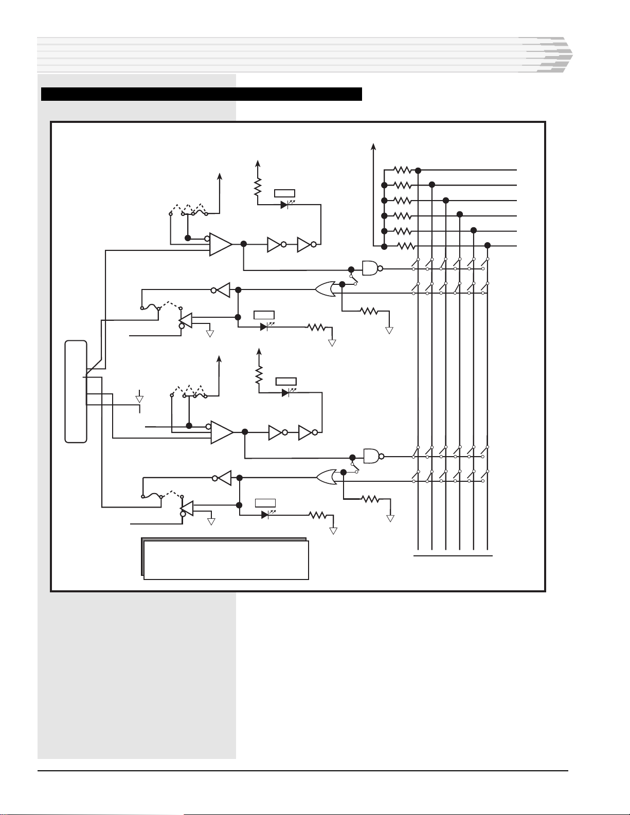
Fig. 1 shows the 46034 Hubbing Module functional schematic.
Ports one through eight operate identically. Refer to Tables A
and B for specific pin assignments. Mini-jumpers 1A through 8A
selects port operation of RS-232, RS-422 terminated, or RS-422
unterminated data. Received data is inverted and goes to the
data bus for distribution. The received signal illuminates the
front panel RX LED.

46034-0997<90-00030> PAGE 3
The data bus consists of six individual, switch selectable data
lines which route the data to the desired ports. Data received
from the data bus applies to one input of a two-input OR gate.
The other OR gate input connects to switch S22 for full- or
half-duplex operation.
When switch S22 is in full-duplex mode (switch open), a con-
stant low applies to the input, which passes all data received
from the data bus to the port transmit circuitry. When S22 is in
half-duplex mode (switch closed), the input operates with the
port receive circuitry.
When the port is not receiving data, the input holds in the low
state and the OR gate passes data received from the data bus.
When the port receives data the input fluctuates between high
and low, enabling and disabling the OR gate and preventing port
data transmission.
The OR gate output applies to a driver that transmits data
through the RS-232 or RS-422 interface, depending on the strap
selection of mini-jumpers 1B through 8B. The signal illuminates
the front panel TX LED.
The ninth data port provides a mounting for installing various
communication subassemblies. With the five six-lever DIP
switches, the port supports the following interfaces:
♦TTL
♦RS-232
♦RS-422
♦RS-485
♦202 tone modem
The ninth data port has CA (pin 36) and CF (pin 18) control
leads for RS-232 subassembly applications.
When using a tone modem subassembly, strap C may be config-
ured to allow modem control by RTS command or strapped for
RTS always enabled. Use strap D for full- or half-duplex opera-
tion. When the strap is in the 1 position, the port operates in
full-duplex mode; when in the 2 position, the port operates in
half-duplex mode.
When the ninth data port is used with a bypass card subassem-
bly, front panel LEDs indicate RXD (receive data) and TXD
(transmit data) activity. When the ninth port is used with any
other communications subassembly, module and subassembly
LEDs indicate receive and transmit activity. Refer to the subas-
sembly documentation for LED operation information.
The 46034 Hubbing Module has an on-board power supply that
operates on -21 to -56 VDC input power. The unit supplies
±12 VDC and +5 VDC that powers the module circuits and an
on-board subassembly.
CIRCUIT DESCRIPTION

PAGE 4 46034-0997<90-00030>
CIRCUIT DESCRIPTION
FIG. 1 - 46034 HUBBING MODULE FUNCTIONAL SCHEMATIC
TX+
+5 VDC
1
49
50
47
48
45
46
A
B
C
D
E
F
REF
RXD
RX1
TX1
1
RS-232
+5 VDC
REF
STRAP 1A-8A
2RS-422
3
1
4
3
RX1 +
RS-232 RS-422
Input
Data
Port
Data Port 1 S22 1-8
RS-232
12
2
TX1 +
Strap 1B-8B
RS-422
Output
Data
Port
+5 VDC
TDX
+5 VDC
TX-
CA
RX+
RX-
CF
54
53
36
56
55
18
RXD
TXD
CTS
RTS
DCD
DTR
DSR
1
2
Strap D
Strap
C
2
+5 VDC
-12 VDC
+12 VDC
RXD
TXD
CTS
RTS
DCD
39
41
43
42
40
-21 to -56
VDC
35
17
TTL
PORT
RX1 -RD1
TD1
TX1 -
Data
Port
9
(Subassembly)
Refer to Fig 8 in
Installation
Section for
specific
pin usage
Power
Supply
Note: Data ports
2 thru 8 are identical
in operation to port 1
(pins 5-16, 19-34)
Bypass
Card
or Subass'y
Modem,
Current
Loop
Etc.
DATA
DATA
DATA
DATA
DATA
DATA
TTL
PORT

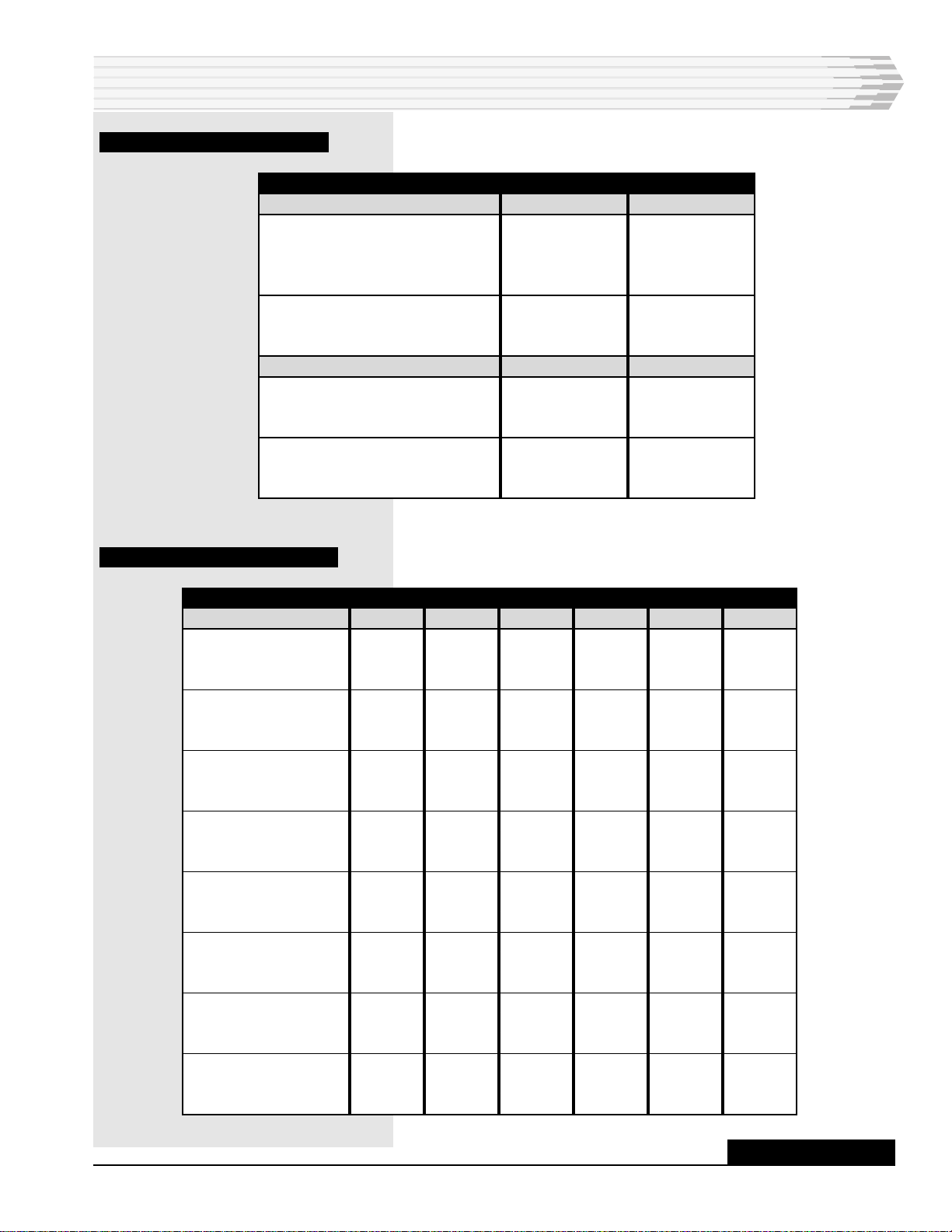
46034-0997<90-00030> PAGE 5
TABLE A - PC PIN ASSIGNMENT FOR RS-422 PORTS
CIRCUIT DESCRIPTION
PORT NUMBER
1
2
3
4
5
6
7
8
RS-422 TX+
Pin 2
Pin 6
Pin 10
Pin 14
Pin 20
Pin 24
Pin 28
Pin 32
RS-422 TX-
Pin 1
Pin 5
Pin 9
Pin 13
Pin 19
Pin 23
Pin 27
Pin 31
RS-422 RX+
Pin 3
Pin 7
Pin 11
Pin 15
Pin 21
Pin 25
Pin 29
Pin 33
RS-422 RX-
Pin 4
Pin 8
Pin 12
Pin 16
Pin 22
Pin 26
Pin 30
Pin 34
TABLE B - PC PIN ASSIGNMENT FOR RS-232 PORTS
PORT NUMBER
1
2
3
4
5
6
7
8
RS-232 TD
Pin 2
Pin 6
Pin 10
Pin 14
Pin 20
Pin 24
Pin 28
Pin 32
RS-232 RD
Pin 4
Pin 8
Pin 12
Pin 16
Pin 22
Pin 26
Pin 30
Pin 34
PAGE 6 46034-0997<90-00030>
APPLICATION INFORMATION
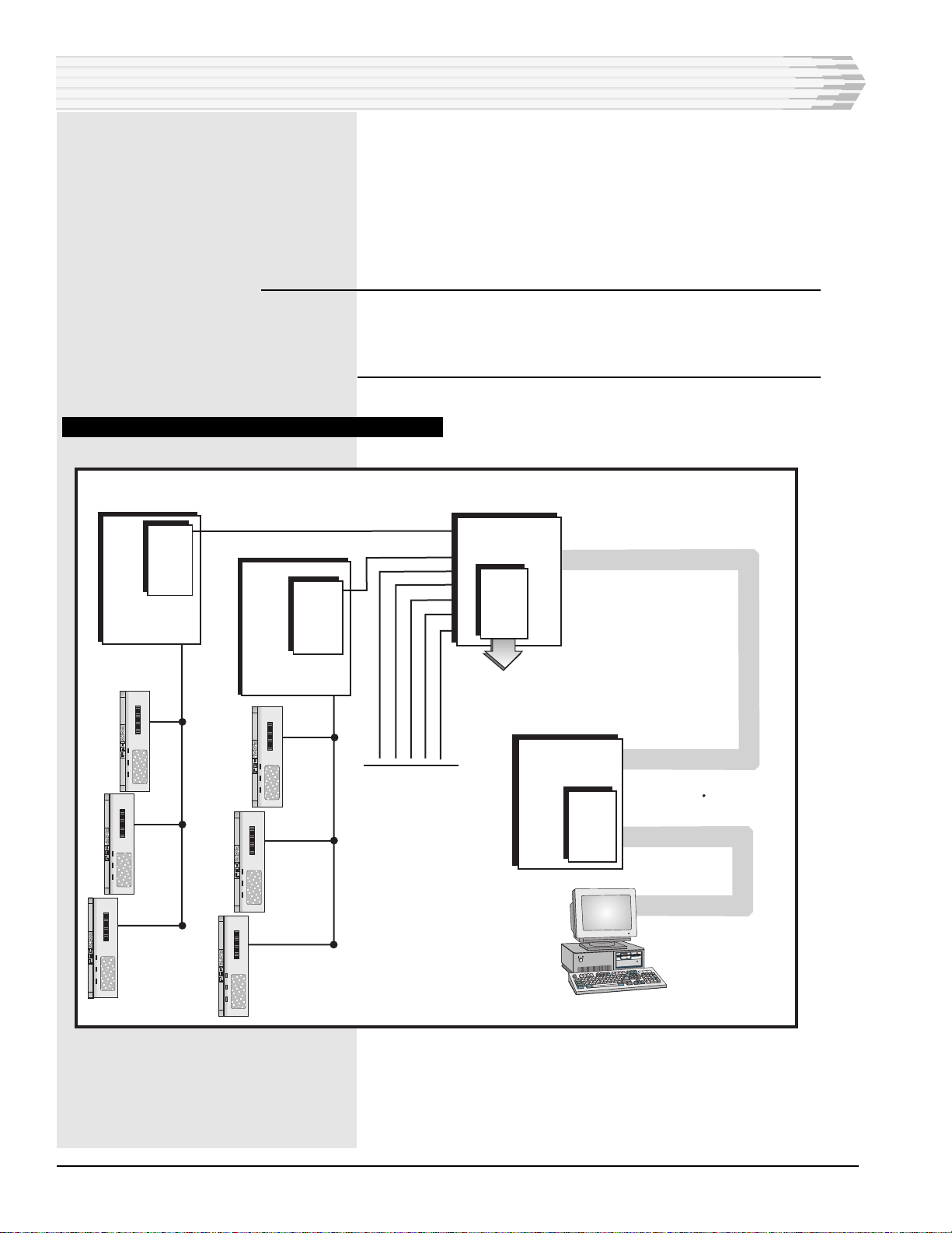
Fig. 2 shows a 46034 Hubbing Module application diagram.
The 46034 Hubbing Module is used primarily with Dantels
460 Alarm and Control System (460 ACS) and provides digital
data summing, distribution and bridging for the 460 ACS data
polling function. The unit can also be used with an on-board
subassembly for other data communications features such as a
modem or current loop interface.
Note: Use each of the six buses carrying data between the data
communication ports for one data polling system only. If more
than one alarm polling systems data routes to a bus, the
system does not function properly.
FIG. 2 - 46034 HUBBING MODULE APPLICATION DIAGRAM
46020
Multple Alarm
Processor
Comm.
Subass'y
(RS-232) Master Port
Data Port (TTL)
46034
Hubbing
Module
Floor 1
46030
Control Point
Module
(CPM)
Floor 2
46030
Control Point
Module
(CPM)
Floor 3
To / From Other
CPM's
Comm. Subass'y
MAT
MAT
MAT
MAT
Alarm Center
RS-422
RS-422
Local Site
(At Building)
49008
Comm.
Subass'y
49008
Comm.
Subass'y
Comm.
Subass'y
To / From
Remote Sites
MAT
MAT

46034-0997<90-00030> PAGE 7
APPLICATION INFORMATION
SUMMING AND DISTRIBUTION APPLICATIONS
Fig. 3 shows a switch setting diagram for summing applications.
Each data port to be summed has its bus output switched to the
bus. The data port that is to receive the summed data from the
contributing data ports has only its bus input switched to the
bus. The switches also can be set for distribution of communica-
tions using a common data bus. The input from one port distrib-
utes to the output of the other ports.
The modules data communication buses route to the edge
connector which allows for bus expansion (pins 45 through 50).
Additional 46034 Hubbing Modules can share any or all of the
same buses which provides data summing/distribution/bridging
between data ports in different modules.
BRIDGING APPLICATIONS
Fig. 4 shows a switch setting diagram for bridging applications
using half-duplex communication. Each data port on the data
bridge must have bus input and output switches set to the bus
being used. Because each data ports bus input and output feed
to a common OR gate, the data port putting data on the bus
cancels its own input at the OR gate.
Fig. 5 shows a switch setting diagram for an RS-232 bridging
application using full-duplex communication. Module strapping
lets each data port provide either an RS-232 or RS-422 data
interface to the six data buses.
When strapped for RS-422 data, each of the eight data ports
receives and transmits data. When strapped for an RS-232
interface, two data ports may be required for each interface,
which limits the functioning data ports to four (not including
port nine). If CF and CA leads are not used, all eight ports are
available.

PAGE 8 46034-0997<90-00030>
APPLICATION INFORMATION
DIP Switch S1
All Switches=Off
Data Ports 4 through 8 are treated the same
as 1, 2 and 3 shown above strapped for RS-422
DIP Switch S9-4=On
All Others=Off
DIP Switch S2-4=On
All Others=Off
DIP Switch S10
All Switches=Off
DIP Switch S3-4=On
All Others=Off
DIP Switch S11
All Switches=Off
49
50
47
48
45
46
A
B
C
D
E
F
REF
7
8
3
21
+5 VDC
RX1
S22-7
TX1
12
6
5
Strap 1B - 8B
REF
11
12
3
21
+5 VDC
RX1
S22-6
TX1
12
10
9
Strap 1B - 8B
REF
3
4
3
21
+5 VDC
RX1
S22-8
TX1
12
2
1
Strap 1B - 8B
DATA
DATA
DATA
DATA
DATA
DATA
RS-232
RS-422
RS-232
RS-422
RS-232
RS-422
RS-232 RS-422
RS-232
RS-422
RS-232 RS-422
+5 VDC
Buses A-F
To Other
Data Ports
Data
Port
1
(Summed
Output)
Input
(NC)
Strap
1A - 8A
Data
Port
2
(Input
Only)
Input
Strap
1A - 8A
Data
Port
3
(Input
Only)
Input
Strap
1A - 8A
Output
(NC)
Output
(NC)
TTL PORT
FIG. 3 - SWITCH SETTING DIAGRAM FOR SUMMING APPLICATIONS

46034-0997<90-00030> PAGE 9
APPLICATION INFORMATION
DIP Others=Off
Data Ports 1 and 2 are shown strapped for RS-422
as examples. all other Data Ports are treated similarly
DIP Switch S9-1=On
All Others=Off
DIP Switch S2-1=On
All Others=Off
DIP Switch S10-1=On
All Switches=Off
49
50
47
48
45
46
A
B
C
D
E
F
REF
7
8
3
21
+5 VDC
RX1
S22-7
TX1
12
6
5
Strap 1B - 8B
3
4
3
21
+5 VDC
RX1
S22-8
TX1
12
2
1
Strap 1B - 8B
RS-232 RS-422
RS-232 RS-422
REF
RS-422 RS-232
RS-422 RS-232
+5 VDC
Buses A-F
To Other
Data Ports
Data
Port
1
Input
Strap
1A - 8A
Data
Port
2
Input
Strap
1A - 8A
Output
Output
DATA
DATA
DATA
DATA
DATA
DATA
TTL
PORT
FIG. 4 - SWITCH SETTING DIAGRAM FOR BRIDGING APPLICATIONS (HALF-DUPLEX)
PAGE 10 46034-0997<90-00030>
APPLICATION INFORMATION
49
50
47
48
45
46
A (BB)
B (BA)
C (CF)
D (CA)
E
F
REF
7
CF 8
3
21
+5 VDC
RX1
S22-7
TX1
12
CA 6
5
Strap 1B - 8B
REF
RX (BB) 4
3
21
+5 VDC
RX1
S22-8
TX1
12
Unused 1
Strap 1B - 8B
RS-232 (2 Data Ports = RS-232 Port)
TX (BA) 2
Input
Only
Switched
To Data
Buses
Input
Only
Switched
To Data
Buses
RX (BB)
TX (BA)
(CF)
(CA)
To External
Equipment
TTL
PORT
DATA
DATA
DATA
DATA
DATA
DATA
+5 VDC
Buses A-F
To Other
Data Ports
Data Port 1 RS232
Strap
1A - 8A
Data Port 2
RS-232
Strap
1A - 8A
Unused
Two ports are required for each RS-232, if the CA and
CF leads are to be used. For bridging application, put
BB and BA on same bus; CA and CF on same bus. For
summing application, put output BB port on BA bus; put
output CA port on CF bus.
17
RS-232 RS-422
RS-232
RS-422
RS-422
RS-232
RS-422 RS-232
FIG. 5 - SWITCH SETTING DIAGRAM FOR RS-232 APPLICATION (FULL-DUPLEX)

46034-0997<90-00030> PAGE 11
INSTALLATION
Installation consists of installing the subassembly, setting the
module straps and switches, wiring the connector, and install-
ing the module in the equipment housing.
1. Install the subassembly.
If a different subassembly is to be installed, remove the three
screws from the subassembly mounting standoffs and carefully
pull the subassembly out of its connections.
If a TTL subassembly (bypass card) was installed, remove the
blue hole plug from the front panel subassembly window.
Install the new subassembly. Refer to Fig. 6. Ensure the subas-
sembly connector pins go into module receptacles J4 and J5. The
subassembly should sit down on the standoffs and the subas-
sembly front panel (except for the TTL subassembly) should
appear straight in the module front panel opening.
Reinstall the screws on the mounting standoffs.
FIG. 6 - SUBASSEMBLY AND POWER SUPPLY LOCATIONS
CONTINUED . . .
Current Loop
or
Tone Modem
Retaining
Screws
Power Supply
Retaining
Screws
PAGE 12 46034-0997<90-00030>
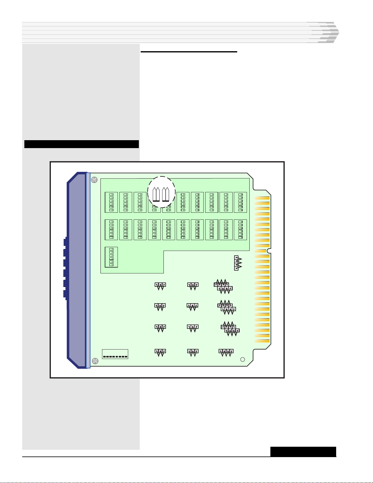
2. Set the straps and switches.
Set the straps by removing the power supply. Remove the three
retaining screws from the subassembly and carefully pull the
subassembly out of its connections.
Once strapping had been verified or corrected, replace the power
supply subassembly by aligning the module connector pins with
the subassembly connector pins. Gently press the power supply
into place. Install the three retaining screws.
Refer to Fig. 7 and Tables C and D for setting straps and
switches.
FIG. 7 - SWITCH AND STRAP LOCATIONS
INSTALLATION
CONTINUED . . .
123456
ON
123456
ON
123456
ON
123456
ON
123456
ON
123456
ON
123456
ON
123456
ON
123456
ON
123456
ON
123456
O
123456
ON
123456
O
123456
ON
123456
ON
123456
ON
123456
ON
123456
ON
123456
ON
123456
ON
123456
O
S17 S18 S1 XX XX S4 S5 S6 S7 S8
S19 S20 S9 S10 S11 S12 S13 S14 S15 S16
S21
D
1 2
C
1 2
3A 2A
2 1 3
2 1 3
5A 4A
2 1 3
6A
2 1 3
1A
2 1 3
2B
1 2
4B
1 2
6B
1 2
8B
1 2
1B
1 2
3B
1 2
5B
1 2
7B
1 2
3
1
2
S22
1 8
8A
7A
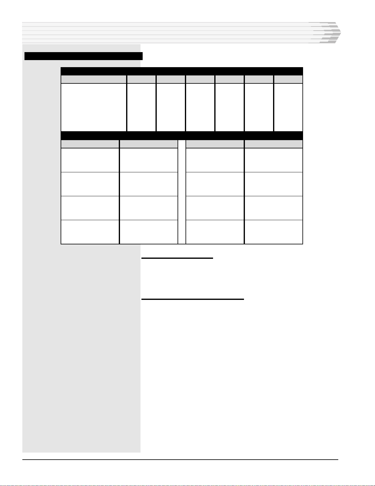
46034-0997<90-00030> PAGE 13
TABLE C - STRAP OPTIONS
TABLE D - SWITCH SETTINGS
INSTALLATION
DATA PORT NUMBER SWITCH
Port 1
Input
Output
Port 2
Input
Output
Port 3
Input
Output
Port 4
Input
Output
Port 5
Input
Output
Port 6
Input
Output
Port 7
Input
Output
Port 8
Input
Output
BUS A
S1-1
S9-1
S2-1
S10-1
S3-1
S11-1
S4-1
S12-1
S5-1
S13-1
S6-1
S14-1
S7-1
S15-1
S8-1
S16-1
BUS B
S1-2
S9-2
S2-2
S10-2
S3-2
S11-2
S4-2
S12-2
S5-2
S13-2
S6-2
S14-2
S7-2
S15-2
S8-2
S16-2
BUS C
S1-3
S9-3
S2-3
S10-3
S3-3
S11-3
S4-3
S12-3
S5-3
S13-3
S6-3
S14-3
S7-3
S15-3
S8-3
S16-3
BUS D
S1-4
S9-4
S2-4
S10-4
S3-4
S11-4
S4-4
S12-4
S5-4
S13-4
S6-4
S14-4
S7-4
S15-4
S8-4
S16-4
BUS E
S1-5
S9-5
S2-5
S10-5
S3-5
S11-5
S4-5
S12-5
S5-5
S13-5
S6-5
S14-5
S7-5
S15-5
S8-5
S16-5
BUS F
S1-6
S9-6
S2-6
S10-6
S3-6
S11-6
S4-6
S12-6
S5-6
S13-6
S6-6
S14-6
S7-6
S15-6
S8-6
S16-6
CONTINUED . . .
OPTION
DATA PORTS 1 THROUGH 8
Receive
RS-232
RS-422 unterminated
RS-422 terminated
Transmit
RS-232
RS-422
COMMUNICATIONS SUBASSEMBLY
Subassembly RTS Select
Command RTS
RTS always ON
Subassembly Duplex Control
Half-duplex
Full-duplex
STRAP
1A through 8A
1A through 8A
1A through 8A
1B through 8B
1B through 8B
C
C
D
D
POSITION
3
1
2
1
2
1
2
2
1
PAGE 14 46034-0997<90-00030>
INSTALLATION
TABLE D (CONTINUED)- SWITCH SETTINGS
3. Wire the connector.
The 56-pin connector is usually prewired at the factory. If you
wire the connector, refer to Fig. 8 for the module connector pin
wiring assignments.
4. Install the module in the shelf.
DATA PORT NUMBER SWITCH
Port 9 (subassembly)
RXD
RTS
TXD
DCD
CTS
BUS A
S17-1
S18-1
S19-1
S20-1
S21-1
BUS B
S17-2
S18-2
S19-2
S20-2
S21-2
BUS C
S17-3
S18-3
S19-3
S20-3
S21-3
BUS D
S17-4
S18-4
S19-4
S20-4
S21-4
BUS E
S17-5
S18-5
S19-5
S20-5
S21-5
BUS F
S17-6
S18-6
S19-6
S20-6
S21-6
DUPLEX ON PORTS 1-8
SWITCH
S22-8 OFF
S22-8 ON
S22-7 OFF
S22-7 ON
S22-6 OFF
S22-6 ON
S22-5 OFF
S22-5 ON
PORT
Port 1
Full-duplex
Half-duplex
Port 2
Full-duplex
Half-duplex
Port 3
Full-duplex
Half-duplex
Port 4
Full-duplex
Half-duplex
SWITCH
S22-4 OFF
S22-4 ON
S22-3 OFF
S22-3 ON
S22-2 OFF
S22-2 ON
S22-1 OFF
S22-1 ON
PORT
Port 5
Full-duplex
Half-duplex
Port 6
Full-duplex
Half-duplex
Port 7
Full-duplex
Half-duplex
Port 8
Full-duplex
Half-duplex

46034-0997<90-00030> PAGE 15
INSTALLATION
FIG. 8 - 46044 HUBBING MODULE PIN DESIGNATIONS
56 55
54 53
52 51
50 49
48 47
46 45
44 43
42 41
40 39
38 37
36 35
34 33
32 31
30 29
28 27
26 25
24 23
22 21
20 19
18 17
16 15
14 13
12 11
10 9
87
65
43
21
CIRCUIT SIDE
OF PC BOARD
COMPONENT SIDE
OF PC BOARD
Subassembly (See table below)
Subassembly (See table below)
Subassembly (See table below)Subassembly (See table below)
Bus ABus B
Bus CBus D
Bus EBus F
CTS
TXDRTS
RXDDCD
-Battery Input (-21 to -56VDC)Subassembly (See table below)
Port 8: RS-422 RX+Port 8: RS-422 RX-; RS-232 RD
Port 8: RS-422 TX-Port 8: RS-422 TX+; RS-232 TD
Port 7: RS-422 RX+Port 7: RS-422 RX-; RS-232 RD
Port 7: RS-422 TX-Port 7: RS-422 TX+; RS-232 TD
Port 6: RS-422 RX+Port 6: RS-422 RX-; RS-232 RD
Port 6: RS-422 TX-Port 6: RS-422 TX+; RS-232 TD
Port 5: RS-422 RX+Port 5: RS-422 RX-; RS-232 RD
Port 5: RS-422 TX-Port 5: RS-422 TX+; RS-232 TD
GroundSubassembly (See table below)
Port 4: RS-422 RX+Port 4: RS-422 RX-; RS-232 RD
Port 4: RS-422 TX-Port 4: RS-422 TX+; RS-232 TD
Port 3: RS-422 RX+Port 3: RS-422 RX-; RS-232 RD
Port 3: RS-422 TX-Port 3: RS-422 TX+; RS-232 TD
Port 2: RS-422 RX+Port 2: RS-422 RX-; RS-232 RD
Port 2: RS-422 TX-Port 2: RS-422 TX+; RS-232 TD
Port 1: RS-422 RX+Port 1: RS-422 RX-; RS-232 RD
Port 1: RS-422 TX-Port 1: RS-422 TX+; RS-232 TD
INTERFACE
RS-422
RS-232
202 Tone
PIN 56
RX+
RD
RCV
PIN 55
RX-
DTR*
RCV
PIN 54
TX+
GND/CTS*
XMT
PIN 53
TX-
TD
XMT
PIN 36
-
RTS
DIST XMT
PIN 18
-
DCD
DIST RCV
* Available for 49029-00 subassembly only.
PAGE 16 46034-0997<90-00030>
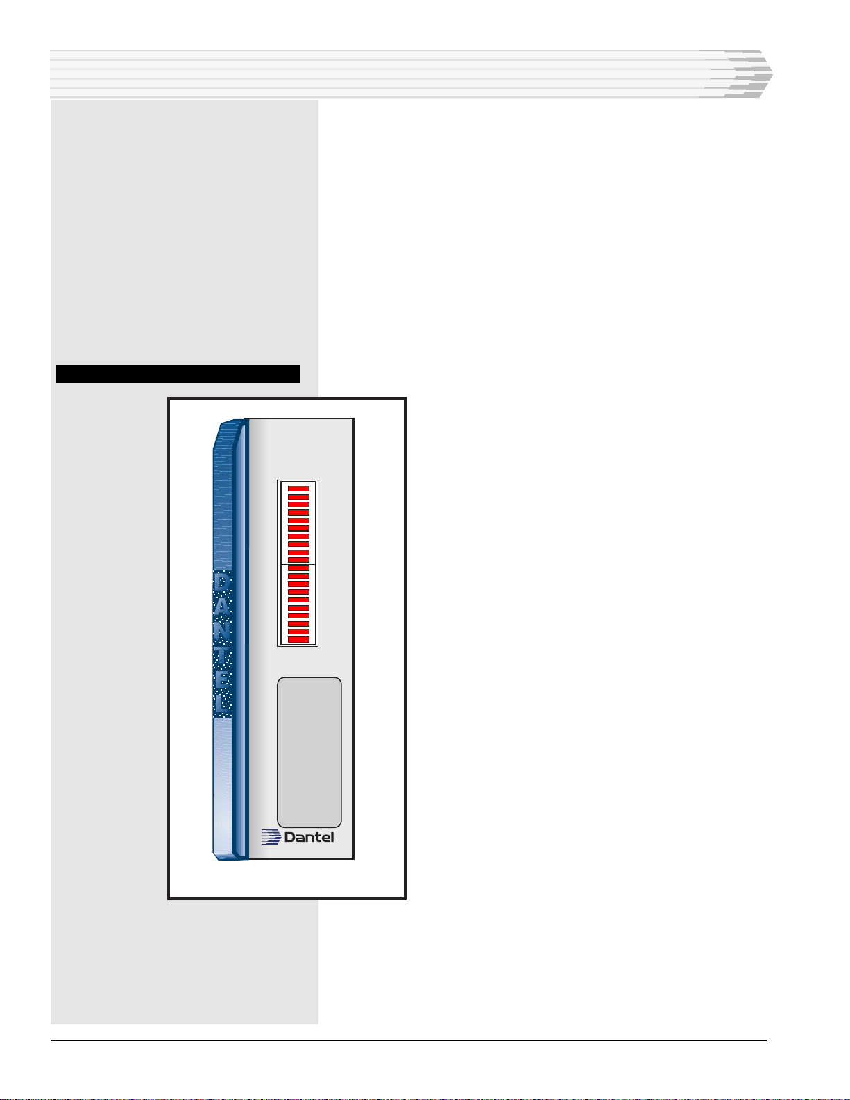
OPERATION
Operation of the 46034 Hubbing Module consists of observing
the 20 front panel LEDs that indicate the activity of all 9
ports. Refer to Fig. 9.
The first eight LEDs, labeled RX1 to RX8 respectively, indicate
receive (RX) activity for data ports one through eight.
The next eight LEDs, labeled TX1 to TX8 respectively, indicate
transmit (TX) activity for data ports one through eight.
The next two LEDs are not labeled and do not function.
The last two LEDs, labeled RXD and TXD, indicate data trans-
mit (TXD) and data receive (RXD) activity for the communica-
tions subassembly (port nine).
FIG. 9 - 46034 FRONT PANEL VIEW
46034-00 REV__
46034-00
HUBBING
MODULE
RX 1
RX 2
RX 3
RX 4
RX 5
RX 6
RX 7
RX 8
TX 1
TX 2
TX 3
TX 4
TX 5
TX 6
TX 7
TX 8
RXD
TXD
46034-0997<90-00030> PAGE 17
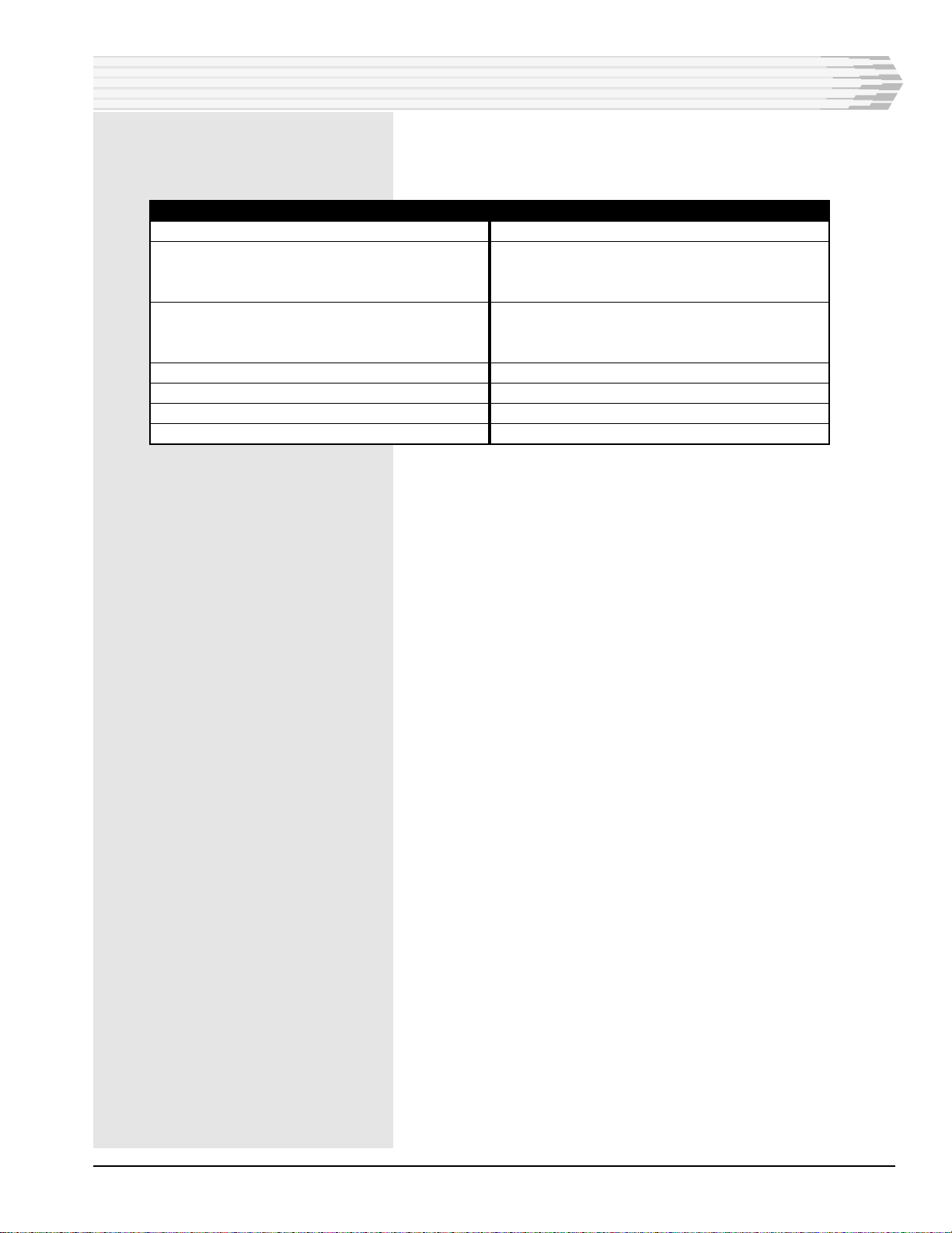
TECHNICAL SPECIFICATIONS
DESCRIPTION
Input Voltage
Input Power (full load; no subassembly)
@ -24 VDC
@ -48 VDC
Heat Dissipation (full load; no subassembly)
@ -24 VDC
@ -48 VDC
Physical Dimensions
Weight
Operating Temperature Range
Data Inputs and Outputs
VALUE
-21 to -56 VDC
64.0 mA
80.0 mA
5.2 BTU/Hr
13.1 BTU/Hr
1.4" x 6.0" x 5.6"
10 ounces
0° to 60° C.
EIA Standards for RS-232 and RS-422

PAGE 18
18 PAGES 46034-0997<90-00030>
LIMITED WARRANTY
The Seller warrants that the standard hardware products sold will be free from defects in material and
workmanship and perform to the Sellers applicable published specifications for a period of 18 months for
hardware, and 3 months for software, from the date of the original invoice. The liability of the Seller hereunder
shall be limited to replacing or repairing, at its option, any defective products which are returned F.O.B. to the
Sellers plant, (or, at the Sellers option, refunding the purchase price of such products). In no case are products
to be returned without first obtaining permission and a customer return authorization number from the Seller.
In no event shall the Seller be liable for any consequential or incidental damages.
Equipment or parts which have been subject to abuse, misuse, accident, alteration, neglect, unauthorized
repair or installation are not covered by warranty. The Seller shall make the final determination as to the
existence and cause of any alleged defect. No warranty is made with respect to custom equipment or products
produced to the Buyers specifications except as specifically stated in writing by the Seller in the contract for
such custom equipment.
This warranty is the only warranty made by the Seller with respect to the goods delivered hereunder, and may
be modified or amended only by a written instrument signed by a duly authorized officer of the Seller and
accepted by the Buyer.
Warranty and remedies on products not manufactured by the Seller are in accordance with warranty of the
respective manufacturer. THE SELLER MAKES NO OTHER WARRANTY OF ANY KIND WHATSOEVER,
EXPRESSED OR IMPLIED; AND ALL IMPLIED WARRANTY OF FITNESS FOR A PARTICULAR PUR-
POSE WHICH EXCEEDS THE AFORESAID OBLIGATIONS IS HEREBY DISCLAIMED BY THE SELLER.
INCASE OF DIFFICULTY
If you experience difficulty with this equipment, check the following, as appropriate:
1. Switch settings
2. Signal levels
3. Software configuration
4. Connections between Dantel’s equipment and your equipment.
If there is still a problem, substitute equipment that is known to be good. For additional assistance, call
Dantels Technical Field Service Department weekdays, 6 A.M. to 5 P.M. pacific time:
1-800-4DANTEL (1-800-432-6835).
If a thorough checkout shows a piece of equipment has malfunctioned, you may return it to the factory. For
repairs and emergency replacements, obtain a Return Material Authorization (RMA) number from the Cus-
tomer Service Representative at 1-800-4DANTEL (1-800-432-6835).
To ensure expedient processing of your order, provide a purchase order number and shipping and billing
information when requesting an RMA number. Also, when the units are returned to Dantel, include a descrip-
tion of the failure symptoms for each unit returned. Send defective equipment to:
Dantel, Inc. • 2991 North Argyle Avenue • Fresno, California 93727-1388
P.O. Box 55013 • Fresno, CA 93747-5013 Phone (209) 292-1111 Fax (209) 292-9355 http://www.dantel.com
WARRANTY
This manual suits for next models
1
Table of contents


